Synthesis of cyclic organic carbonates via catalytic oxidative carboxylation of olefins in flow reactors†
Ajay A.
Sathe
a,
Anirudh M. K.
Nambiar
b and
Robert M.
Rioux
*ab
aDepartment of Chemistry, The Pennsylvania State University, University Park, PA 16802, USA. E-mail: rioux@engr.psu.edu; Fax: 814 865 7846; Tel: 814 867 2503
bDepartment of Chemical Engineering, The Pennsylvania State University, University Park, PA 16802, USA
First published on 25th November 2016
Abstract
Methodology for direct catalytic conversion of olefins into cyclic carbonates using peroxide and carbon dioxide under relatively mild conditions is demonstrated. The protocol utilizes packed bed flow reactors in series to couple rhenium catalyzed olefin epoxidation and aluminum catalyzed epoxide carboxylation in a single sequence.
Organic carbonates are versatile molecules serving as raw materials for polycarbonate and polyurethane synthesis,1 green solvents,2 gasoline additives,3,4 electrolytes in energy storage devices,5–7 and fine chemical intermediates.8–12 While acyclic carbonates are produced by oxidative carbonylation of alcohols or phenols, the five membered cyclic carbonates can be produced from diols, or epoxides and a one carbon synthon.13 Traditionally the most commonly used one carbon synthon for carbonate production has been phosgene,14 but its toxicity and low atom economy make this route unattractive. Alternatively, carbon dioxide is an ideal C1 synthon due to its low cost, low toxicity, and wide availability.15–20 The reaction of carbon dioxide and epoxide represents a 100% atom efficient approach for the production of cyclic carbonates and is one of the few industrially relevant reactions utilizing carbon dioxide.21,22
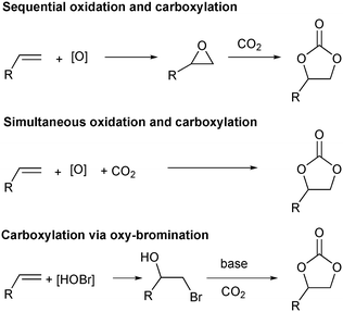
A more straightforward approach to the synthesis of these important molecules would be the direct oxidative carboxylation of olefins. Such a process would obviate the need for isolation and purification of, often unstable and highly reactive epoxides. The strategies for oxidative carboxylation can be broadly classified into: i) sequential one-pot oxidation followed by carboxylation,23 ii) simultaneous one-pot oxidation and carboxylation,24–26 and iii) carboxylation via oxy-halogenation (Scheme 1).27–31 Only a handful of examples of catalytic approaches to organic carbonates from olefins are known. Although these present an excellent proof-of-concept, they suffer from low yields, low selectivity, long reaction times, and are applicable to very specific substrates.24,25,28,29 The utility of the elegant work by the Jamison group describing the flow synthesis of these molecules is mitigated only by the use of super-stoichiometric bromide reagents and the subsequent waste generation.30,31 Of the described strategies for oxidative carboxylation, sequential epoxidation and carboxylation are most suited for the design of a catalytic approach as both the individual reactions, olefin epoxidation and epoxide carboxylation, are well studied. The challenge associated with conducting these reactions in a single pot comes from the fact that an oxidant is essential to carry out the epoxidation reaction, but it is incompatible with the carboxylation catalyst system which usually employs a Lewis base. Hydrogen peroxide is the oxidant of choice for the epoxidation reaction as it produces water as the only by-product. This however, leads to a biphasic epoxidation reaction (as most olefins are hydrophobic) and hence requires long reaction times as mass transfer across the aqueous–organic interface control the rate of the reaction.32 Reaction rates are proportional to the extent of this interface, which can be increased by mixing or by a reduction in volume of the individual phases. The latter can be achieved through reactor configurations leading to an increased surface area to volume ratio.
Flow chemistry has emerged as an enabling technology which can be utilized to overcome both of these problems.33–40 The superior surface area to volume ratio afforded by flow reactors make them especially advantageous for carrying out multiphase reactions due to increased interfacial area between phases.41–43 For reactions involving gases, flow reactors provide an added advantage of increased process safety by enabling superior control over the amount of gas required for the reaction, while also eliminating the need for highly capital intensive pressure vessels required to maintain a constant pressure in the headspace above the reaction mixture.44,45 Finally, flow processes enable multicomponent reactions which employ mutually incompatible reagents by allowing sequential introduction of reagents at different points, both spatially and temporally.30,46,47 We describe here the utility of flow reactors by presenting a direct catalytic synthesis of cyclic organic carbonates starting from olefins and utilizing carbon dioxide. Our strategy involves a rhenium catalyzed epoxidation of the olefin followed by trapping the epoxide by CO2 in the presence of an aluminum catalyst and iodide salt. The key to the success of this methodology is the use of a membrane separator to compartmentalize the mutually incompatible oxidizer and the Lewis basic carboxylation catalyst system.
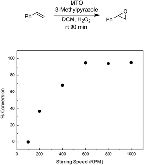
The methyltrioxorhenium (MTO) catalyzed epoxidation of olefins is an efficient and general methodology employing H2O2 as a benign and green terminal oxidant.48,49 The system is also highly selective towards the epoxide. We started our investigation by employing styrene as a model substrate. During preliminary batch investigations we noted that the conversion of styrene to styrene oxide was influenced by the rate of mixing, with negligible conversion at 100 rpm which increased to around 95% at 600 rpm (Fig. 1). Increasing the stirring rate further had no effect on the conversion. This confirmed our hypothesis that the rate of epoxidation is influenced by the rate of mass transfer across the aqueous–organic interface.
 | ||
| Fig. 1 Effect of stirring speed on conversion of styrene to styrene oxide. Conditions: styrene (3 mmol), MTO 0.03 mmol, 3-methylpyrazole: 0.72 mmol, H2O2: 6 mmol. Conversions based on GC-FID analysis of crude reaction mixture. See ESI† for details. | ||
A packed bed reactor, made from polytetrafluoroethylene (PTFE) tubing and packed with sand, was utilized to maximize the contact between the two phases.50 PTFE was chosen as the material of construction because stainless steel is known to decompose H2O2.51 Only 1 mol% catalyst was found to be sufficient to effect almost complete conversion of styrene to styrene oxide at 40 °C in 30 min (Fig. S2†).
The MTO catalyzed epoxidations have been shown to be markedly improved, both in terms of activity and selectivity, by the use of N-donor ligands, utilized typically at 15–20 fold excess over the MTO catalyst.49,52–54 We decided to utilize 3-methylpyrazole at an optimum of 24 mol% loading (Table 1 entries 2–4, Fig. S3†) owing to its demonstrated activity in the epoxidation of a wide variety of olefin substrates.55 Deviation from the optimized temperature led to lower conversion (Table 1 entries 7–9, Fig. S4†), which at higher temperatures was attributed to catalyst decomposition.56 An excess of the oxidant was required to achieve good conversion of the olefin within 30 min (Table 1, entries 6, 10, 11, Fig. S5†). Although 30 min was found to be sufficient time for almost complete conversion of styrene (Fig. S6†) we employed 45 min in the subsequent substrate scope studies to negate any effect of the change in steric or electronic properties of the olefin employed. Finally, we optimized the styrene concentration to 4 M which provided a high concentration of the epoxide for the next step of the reaction sequence, while ensuring solubility of all reactants, including the epoxides. (Fig. S7†).
| Entry | Catalyst loading (mol%) | Co-catalyst loading (mol%) | Residence time (min) | Temp (°C) | H2O2 equiv. | Conversiona (%) |
|---|---|---|---|---|---|---|
| a Conversions based on GC-FID analysis of reaction mixture using dodecane as internal standard. See ESI for details. | ||||||
| 1 | 0.5 | 12 | 30 | 40 | 5 | 78 |
| 2 | 1 | 24 | 30 | 40 | 5 | 97 |
| 3 | 1 | 12 | 30 | 40 | 5 | 82 |
| 4 | 1 | 6 | 30 | 40 | 5 | 68 |
| 5 | 1 | 24 | 10 | 40 | 5 | 80 |
| 6 | 1 | 24 | 60 | 40 | 5 | 97 |
| 7 | 1 | 24 | 30 | 30 | 5 | 84 |
| 8 | 1 | 24 | 30 | 60 | 5 | 81 |
| 9 | 1 | 24 | 30 | 80 | 5 | 50 |
| 10 | 1 | 24 | 30 | 40 | 3 | 88 |
| 11 | 1 | 24 | 30 | 40 | 1 | 51 |
We next turned our attention towards optimizing epoxide carboxylation utilizing styrene oxide as a model substrate. The carboxylation of epoxides is a well-studied reaction and a variety of systems utilizing a combination of Lewis acids and Lewis bases have been shown to catalyze the transformation.57–59 Amongst them, the aluminum based systems have shown to be most active and were hence chosen in this study.60–62
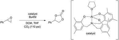
Specifically, an amino trisphenolate complexed aluminum catalyst with a tetrabutylammonium iodide (TBAI) co-catalyst was employed. Stainless steel tubing packed with sand was used as the reactor. We found that a modest 2 mol% catalyst loading in the presence of 10 mol% TBAI was sufficient to obtain complete conversion of styrene oxide to styrene carbonate at 100 °C in 40 min (Fig. S8–S10†). This represents an improvement over the typical conditions found in the literature for these reactions which require longer reactions times or higher temperatures and pressures under neat conditions.60,62 Deviation from these conditions led to a decrease in the yield of the carbonate (Table 2, entries 2–8). We also note that the product is stable under the reaction conditions for extended time (Table 2, entry 9).
| Entry | Catalyst loading (mol%) | TBAI loading (mol%) | Temp. (°C) | Residence time (min) | Conversiona (%) |
|---|---|---|---|---|---|
| a Conversion based on 1H-NMR analysis of crude reaction mixtures. See ESI for details. | |||||
| 1 | 2 | 10 | 100 | 40 | 100 |
| 2 | 2 | 6 | 100 | 40 | 97 |
| 3 | 2 | 2 | 100 | 40 | 49 |
| 4 | 2 | 10 | 80 | 40 | 79 |
| 5 | 2 | 10 | 60 | 40 | 67 |
| 6 | 2 | 10 | 40 | 40 | 62 |
| 7 | 2 | 10 | 100 | 20 | 86 |
| 8 | 2 | 10 | 100 | 30 | 94 |
| 9 | 2 | 10 | 100 | 75 | 100 |
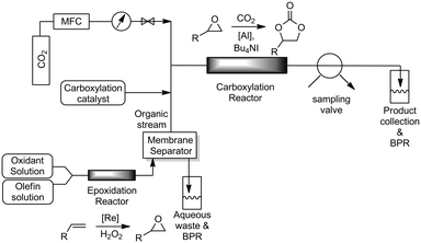
With the individual reactions optimized, we coupled the two reactions to realize our aim of direct oxidative carboxylation. The reactor system was assembled as shown in Fig. 2. The epoxidation and carboxylation reactors were identical to those described above. The organic solution, containing the olefin, catalyst and co-catalyst, and the aqueous peroxide solution were loaded into gas-tight syringes and introduced into the system using syringe pumps. The streams were mixed using a T-mixer, forming a segmented flow pattern, before entering the epoxidation reactor. As the excess peroxide employed in the epoxidation reaction is detrimental to the carboxylation reaction we utilized a PTFE membrane based separator to partition the aqueous and organic phases coming out of the epoxidation reactor. Phase separation is achieved by preferential wetting of the fluoropolymer membrane by the permeating organic phase and retention of the aqueous solution.63 The aqueous phase, which contains the rhenium catalyst, was sent to a bulk collection vessel and the separator outlet containing the organic stream was mixed with the carboxylation catalyst solution in another T-mixer. This solution was then mixed with CO2 gas introduced from a mass flow controller. The gas–liquid segmented flow then entered the carboxylation reactor. The back pressure of the system was set by pressurizing the bulk collection vessels with argon. A slow bleed was maintained in order to ensure steady state conditions. The reaction mixture was withdrawn from the system using a 6-way sampling valve and analyzed using 1H-NMR spectroscopy.
Gratifyingly when styrene was subjected to the reaction conditions quantitative yield of the corresponding carbonate was obtained. The transformation is influenced by steric bulk around the olefin as evidenced by the reduced yield of ortho and meta substituted styrenes (Table 3, entries e and f). Both electron-rich and electron-poor styrenes undergo the reaction; however, internal olefins do not undergo the transformation.64 We found the epoxidation reaction proceeds without complications, but the carboxylation of internal epoxides was not successful under the developed conditions, presumably due to the increased steric bulk around the epoxide ring. The developed protocol can also be extended to aliphatic olefins and functional groups such as halogens and nitrile were well tolerated. Additionally, we note that there is no erosion in the yield of the carbonate when the system was maintained online for a period of 7 hours in the case of oxidative carboxylation of styrene.
The present protocol is limited by the partitioning capability of the epoxides, generated in the first step, between water and the organic phase. As a consequence olefins having low molecular weight or highly polar substituents are not viable substrates for the developed protocol as they are freely miscible with water and hence cannot be separated using the membrane separator. It is important to note that this reaction sequence cannot be carried out in a typical batch set up as the tetrabutylammonium iodide and hydrogen peroxide are incompatible with each other and react violently when mixed. When we ran the reaction in sequential mode using styrene (by separating the peroxide and adding the carboxylation catalyst mixture to the resulting organic layer) we found that the yield of the styrene carbonate was 88%, as compared to a quantitative yield in the flow reactor.
To test whether the separation of the aqueous and organic phase can help with the recycling of the rhenium catalyst, we decided to analyze the partitioning of the Re between the two phases. Unfortunately we found that the Re concentration in the two phases was almost identical, making straightforward recycling difficult.65 However, we believe that this work can also be applied towards heterogeneous supported catalysts which will facilitate the catalyst recovery and reuse.66–69
Conclusions
In summary we have developed a novel strategy for the synthesis of cyclic organic carbonates starting from olefins and utilizing carbon dioxide. Our methodology employs a cheap and green oxidant, is scalable and enables carrying out the reaction under relatively mild conditions of temperature and pressure. We believe the in-line liquid–liquid separation can be utilized as a general strategy to segregate incompatible reagents (Lewis acids and bases, oxidizer and reductants, etc.) and couple syntheses requiring orthogonally reactive intermediates.Acknowledgements
The authors would like to thank Dr. Nicholas Sturgis for helpful discussions in the design and construction of the flow reactors. The National Science Foundation Divison of Materials Research (NSF DMR #1207467) is acknowledged for funding, as well as the Institutes of Energy and the Environment (PSIEE) at the Pennsylvania State University.Notes and references
- A. Reitz, R. Wilhelm and D. Kuckling, Macromol. Symp., 2013, 334, 92–97 CrossRef CAS.
- B. Schäffner, F. Schäffner, S. P. Verevkin and A. Börner, Chem. Rev., 2010, 110, 4554–4581 CrossRef PubMed.
- A. Kowalewicz and M. Wojtyniak, Proc. Inst. Mech. Eng., Part D, 2005, 219, 103–125 CrossRef.
- R. Zevenhoven, S. Eloneva and S. Teir, Catal. Today, 2006, 115, 73–79 CrossRef CAS.
- G. G. Eshetu, J.-P. Bertrand, A. Lecocq, S. Grugeon, S. Laruelle, M. Armand and G. Marlair, J. Power Sources, 2014, 269, 804–811 CrossRef CAS.
- I. Skarmoutsos, V. Ponnuchamy, V. Vetere and S. Mossa, J. Phys. Chem. C, 2015, 119, 4502–4515 CAS.
- R. S. Kühnel, N. Böckenfeld, S. Passerini, M. Winter and A. Balducci, Electrochim. Acta, 2011, 56, 4092–4099 CrossRef.
- V. Laserna, G. Fiorani, C. J. Whiteoak, E. Martin, E. Escudero-Adán and A. W. Kleij, Angew. Chem., Int. Ed., 2014, 53, 10416–10419 CrossRef CAS PubMed.
- A. Khan, L. Yang, J. Xu, L. Y. Jin and Y. J. Zhang, Angew. Chem., Int. Ed., 2014, 53, 11257–11260 CrossRef CAS PubMed.
- A. S. Vitvitskaya, F. B. Naidis, E. Z. Katsnel'son and I. A. Karpinskaya, Pharm. Chem. J., 1981, 15, 512–515 CrossRef.
- P. Tundo and M. Selva, Acc. Chem. Res., 2002, 35, 706–716 CrossRef CAS PubMed.
- W.-C. Shieh, S. Dell and O. Repič, Org. Lett., 2001, 3, 4279–4281 CrossRef CAS PubMed.
- A.-A. G. Shaikh and S. Sivaram, Chem. Rev., 1996, 96, 951–976 CrossRef CAS PubMed.
- D. Ballivet-Tkatchenko and A. Dibenedetto, in Carbon Dioxide as Chemical Feedstock, Wiley-VCH Verlag GmbH & Co. KGaA, 2010, pp. 169–212 Search PubMed.
- M. Aresta and A. Dibenedetto, Dalton Trans., 2007, 2975–2992 RSC.
- T. Sakakura, J.-C. Choi and H. Yasuda, Chem. Rev., 2007, 107, 2365–2387 CrossRef CAS PubMed.
- W. Leitner, Coord. Chem. Rev., 1996, 153, 257–284 CrossRef CAS.
- W. Leitner, Angew. Chem., Int. Ed. Engl., 1995, 34, 2207–2221 CrossRef CAS.
- A. A. Sathe, D. R. Hartline and A. T. Radosevich, Chem. Commun., 2013, 49, 5040–5042 RSC.
- I. Omae, Coord. Chem. Rev., 2012, 256, 1384–1405 CrossRef CAS.
- S. Fukuoka, M. Kawamura, K. Komiya, M. Tojo, H. Hachiya, K. Hasegawa, M. Aminaka, H. Okamoto, I. Fukawa and S. Konno, Green Chem., 2003, 5, 497–507 RSC.
- T. Sakakura and K. Kohno, Chem. Commun., 2009, 1312–1330 RSC.
- R. Srivastava, D. Srinivas and P. Ratnasamy, Catal. Lett., 2003, 91, 133–139 CrossRef CAS.
- M. Aresta and A. Dibenedetto, J. Mol. Catal. A: Chem., 2002, 182–183, 399–409 CrossRef CAS.
- D. Bai and H. Jing, Green Chem., 2010, 12, 39–41 RSC.
- F. Chen, T. Dong, T. Xu, X. Li and C. Hu, Green Chem., 2011, 13, 2518–2524 RSC.
- J. Sun, S.-i. Fujita, B. M. Bhanage and M. Arai, Catal. Today, 2004, 93–95, 383–388 CrossRef CAS.
- N. Eghbali and C.-J. Li, Green Chem., 2007, 9, 213–215 RSC.
- J.-L. Wang, J.-Q. Wang, L.-N. He, X.-Y. Dou and F. Wu, Green Chem., 2008, 10, 1218–1223 RSC.
- J. Wu, J. A. Kozak, F. Simeon, T. A. Hatton and T. F. Jamison, Chem. Sci., 2014, 5, 1227–1231 RSC.
- X. Yang, J. Wu, X. Mao, T. F. Jamison and T. A. Hatton, Chem. Commun., 2014, 50, 3245–3248 RSC.
- The epoxidation of styrene was found to be influenced by the stirring speed during the initial optimization study. See ESI† for more details.
- D. Webb and T. F. Jamison, Chem. Sci., 2010, 1, 675–680 RSC.
- J. C. Pastre, D. L. Browne and S. V. Ley, Chem. Soc. Rev., 2013, 42, 8849–8869 RSC.
- D. T. McQuade and P. H. Seeberger, J. Org. Chem, 2013, 78, 6384–6389 CrossRef CAS PubMed.
- S. G. Newman and K. F. Jensen, Green Chem., 2013, 15, 1456–1472 RSC.
- B. P. Mason, K. E. Price, J. L. Steinbacher, A. R. Bogdan and D. T. McQuade, Chem. Rev., 2007, 107, 2300–2318 CrossRef CAS PubMed.
- G. Jas and A. Kirschning, Chem. – Eur. J., 2003, 9, 5708–5723 CrossRef CAS PubMed.
- J. Wegner, S. Ceylan and A. Kirschning, Adv. Synth. Catal., 2012, 354, 17–57 CrossRef CAS.
- P. Watts and C. Wiles, Org. Biomol. Chem., 2007, 5, 727–732 CAS.
- J.-i. Yoshida, H. Kim and A. Nagaki, ChemSusChem, 2011, 4, 331–340 CrossRef CAS PubMed.
- J. Kobayashi, Y. Mori and S. Kobayashi, Chem. – Asian J., 2006, 1, 22–35 CrossRef CAS PubMed.
- G. N. Doku, W. Verboom, D. N. Reinhoudt and A. van den Berg, Tetrahedron, 2005, 61, 2733–2742 CrossRef CAS.
- M. Brzozowski, M. O'Brien, S. V. Ley and A. Polyzos, Acc. Chem. Res., 2015, 48, 349–362 CrossRef CAS PubMed.
- C. J. Mallia and I. R. Baxendale, Org. Process Res. Dev., 2016, 20, 327–360 CrossRef CAS.
- I. R. Baxendale, J. Deeley, C. M. Griffiths-Jones, S. V. Ley, S. Saaby and G. K. Tranmer, Chem. Commun., 2006, 2566–2568 RSC.
- A. Nagaki, C. Matsuo, S. Kim, K. Saito, A. Miyazaki and J.-i. Yoshida, Angew. Chem., Int. Ed., 2012, 51, 3245–3248 CrossRef CAS PubMed.
- W. A. Herrmann, R. W. Fischer and D. W. Marz, Angew. Chem., Int. Ed. Engl., 1991, 30, 1638–1641 CrossRef.
- J. Rudolph, K. L. Reddy, J. P. Chiang and K. B. Sharpless, J. Am. Chem. Soc., 1997, 119, 6189–6190 CrossRef CAS.
- J. R. Naber and S. L. Buchwald, Angew. Chem., Int. Ed., 2010, 49, 9469–9474 CrossRef CAS PubMed.
- C. C. Lin, F. R. Smith, N. Ichikawa, T. Baba and M. Itow, Int. J. Chem. Kinet., 1991, 23, 971–987 CrossRef CAS.
- W.-D. Wang and J. H. Espenson, J. Am. Chem. Soc., 1998, 120, 11335–11341 CrossRef CAS.
- C. Coperet, H. Adolfsson and K. Barry Sharpless, Chem. Commun., 1997, 1565–1566 RSC.
- H. Adolfsson, A. Converso and K. B. Sharpless, Tetrahedron Lett., 1999, 40, 3991–3994 CrossRef CAS.
- S. Yamazaki, Org. Biomol. Chem., 2007, 5, 2109–2113 CAS.
- No other products were observed by gas chromatography leading us to conclude that the product stability is not an issue. Also the effluent from the reactor was colorless as opposed to bright yellow which is indicative of the rhenium peroxo complex. We also note that the concentration of the peroxide in the effluent was within expected limits, ruling out peroxide decomposition.
- M. North, R. Pasquale and C. Young, Green Chem., 2010, 12, 1514–1539 RSC.
- C. Martín, G. Fiorani and A. W. Kleij, ACS Catal., 2015, 5, 1353–1370 CrossRef.
- W.-L. Dai, S.-L. Luo, S.-F. Yin and C.-T. Au, Appl. Catal., A, 2009, 366, 2–12 CrossRef CAS.
- W. Clegg, R. W. Harrington, M. North and R. Pasquale, Chem. – Eur. J., 2010, 16, 6828–6843 CrossRef CAS PubMed.
- W.-M. Ren, Y. Liu and X.-B. Lu, J. Org. Chem., 2014, 79, 9771–9777 CrossRef CAS PubMed.
- C. J. Whiteoak, N. Kielland, V. Laserna, E. C. Escudero-Adán, E. Martin and A. W. Kleij, J. Am. Chem. Soc., 2013, 135, 1228–1231 CrossRef CAS PubMed.
- A. Adamo, P. L. Heider, N. Weeranoppanant and K. F. Jensen, Ind. Eng. Chem. Res., 2013, 52, 10802–10808 CrossRef CAS.
- Cyclohexene and 4-phenyl-2-butene were tried as model substrates for internal olefins.
- See ESI† for details on the ICP analysis.
- R. Neumann and T.-J. Wang, Chem. Commun., 1997, 1915–1916 RSC.
- K. Kamata, K. Yonehara, Y. Sumida, K. Hirata, S. Nojima and N. Mizuno, Angew. Chem., Int. Ed., 2011, 50, 12062–12066 CrossRef CAS PubMed.
- J. Melendez, M. North and P. Villuendas, Chem. Commun., 2009, 2577–2579 RSC.
- M. North, P. Villuendas and C. Young, Chem. – Eur. J., 2009, 15, 11454–11457 CrossRef CAS PubMed.
Footnote |
| † Electronic supplementary information (ESI) available: Full experimental procedures, reactor set-up and parts list, characterization data, NMR spectra. See DOI: 10.1039/c6cy01974a |
| This journal is © The Royal Society of Chemistry 2017 |


