Is iron nitride or carbide highly active for oxygen reduction reaction in acidic medium?†
Tao
Sun‡
,
Yufei
Jiang‡
,
Qiang
Wu
*,
Lingyu
Du
,
Zhiqi
Zhang
,
Lijun
Yang
*,
Xizhang
Wang
and
Zheng
Hu
*
Key Laboratory of Mesoscopic Chemistry of MOE and Collaborative Innovation Center of Chemistry for Life Sciences, School of Chemistry and Chemical Engineering, Nanjing University, Nanjing 210023, China. E-mail: wqchem@nju.edu.cn; lijunyang@nju.edu.cn; zhenghu@nju.edu.cn
First published on 1st December 2016
Abstract
Currently, iron nitride (Fe2N) and iron carbide (Fe3C), which are regarded as the new non-precious metal electrocatalysts for the oxygen reduction reaction (ORR) with high activity and stability in acidic medium, are attracting increasing attention. Herein, by systematic comparison of the ORR activities for Fe2N- and Fe3C-based catalysts designed with or without a solid nitrogen source, we found that only the former is highly active for ORR while the latter is quite poorly active despite their similar crystalline phases. This result indicates that the Fe–N related species are responsible for the high ORR activities of the Fe-based catalysts, similar to the case of Fe/N/C catalysts. Density functional theory calculations demonstrate that the Fe–N4/C moiety has a far superior ORR activity to that of Fe2N and Fe3C. The experimental and theoretical results mutually support that the high activities of the Fe-based catalysts originate from Fe–Nx/C moieties (x ≥ 4) rather than Fe2N or Fe3C phases, which is significant for exploring advanced Fe-based electrocatalysts.
Proton exchange membrane fuel cells (PEMFCs) are prospective power sources for mobile and stationary applications due to their large power density, high efficiency and low carbon emissions.1 To date, the commercialization of PEMFCs is still hindered by the high cost and limited operational stability of Pt-based catalysts. Now, the main challenge is the design of cheap and stable electrocatalysts for the oxygen reduction reaction (ORR).1,2
Great effort has been devoted to exploring non-precious metal electrocatalysts working in acidic medium, especially the three types, namely metal/nitrogen/carbon (M/N/C),3 nitrides4 and chalcogenides.5 Among them, Fe/N/C catalysts exhibit the closest activity to the Pt-based catalysts and have long-term stability, thus becoming the most promising candidate for replacing noble-metal catalysts.3,6 Many experimental results suggest that Fe–Nx/C moieties (x ≥ 4) are the ORR active sites,7 although their structures have not been completely identified to date.8
Recently, it was reported that iron carbide (Fe3C) was a new type of ORR electrocatalyst with a high onset potential of 0.92 V (vs. RHE) and good stability in acidic medium,9 which has attracted increasing attention.10 In our study on this topic, we noticed that nitrogen-containing sources such as cyanamide and pyrrole were introduced in the preparation of Fe3C catalysts in all the related literature, although Fe–Nx/C moieties (x ≥ 4) were not detected.9,10 It is known that high-temperature pyrolysis of the coexisting iron salt, the nitrogen-containing source, and the carbon support can produce Fe/N/C catalysts with abundant Fe–Nx/C moieties.6,11 And it is reported that the Fe(III) species of high oxidation state in Fe–Nx/C moieties is active for ORR at high potential (0.7 V vs. RHE).11b This situation raises a critical question, i.e., does the ORR activity of the so-constructed Fe3C catalyst originate from the Fe3C phase or the Fe–Nx/C moiety? Very recently, iron nitride (Fe2N) was also reported to be ORR active in acidic medium.12 We noted that a carbon source was used in the preparation of the Fe2N catalyst. Hence, the same critical question also exists, i.e., does the ORR activity stem from the Fe2N phase or the Fe–Nx/C moiety? The clarification of such questions is scientifically interesting and significant, especially for exploring the Fe-based non-precious metal ORR electrocatalysts. Herein we intentionally designed Fe2N- and Fe3C-based catalysts with or without a nitrogen source during preparation, and four typical Fe-based catalysts were obtained. By detailed characterization and systematic comparison, it is demonstrated that the high ORR activities of this kind of new catalysts originate from the trace of Fe–Nx/C moieties rather than the Fe2N or Fe3C phases, which is supported by our theoretical simulations.
Carbon nanocages (CNCs) and nitrogen-doped CNC (NCNC, N content: ∼11.4 at%), with comparable specific surface area (∼1500 m2 g−1) and similar structure, were used as pure and N-doped carbon supports, respectively, which were prepared by an in situ MgO template method as described in our recent papers (ESI-1†).13
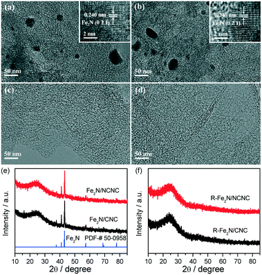
For the Fe2N-based catalysts, Fe2N nanoparticles were loaded on NCNCs and CNCs by impregnation and nitridation, similar to our recent synthesis of alloyed Co–Mo nitride ORR catalyst, designated as Fe2N/NCNC and Fe2N/CNC, respectively. The same Fe loading of 10 wt% was used (experimental section).4aFig. 1 displays the transmission electron microscopy (TEM) and X-ray diffraction (XRD) characterization of the catalysts. Both catalysts possess the pure Fe2N phase with particle sizes of 20–100 nm (Fig. 1a, b and e). The Fe2N nanoparticles can be removed by leaching with 0.5 mol L−1 H2SO4, denoted as R-Fe2N/NCNC and R-Fe2N/CNC (Fig. 1c, d and f, ESI-2†).
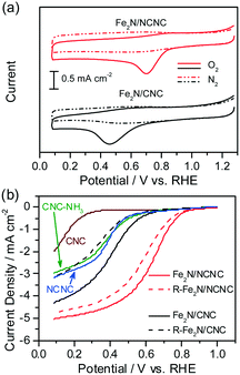
Fig. 2 shows the cyclic voltammograms (CVs) and rotating disk electrode (RDE) voltammetry of the two catalysts as-prepared and after the removal of Fe2N nanoparticles. In comparison with the featureless cases in the N2-saturated electrolyte, obvious ORR signals appear on the CVs measured in the O2-saturated H2SO4 solution, indicating their apparent ORR activities (Fig. 2a). The ORR peak potential of Fe2N/NCNC is 0.704 V (vs. RHE), much higher than that of Fe2N/CNC (0.464 V). RDE curves also reflect the distinct ORR activities with a much higher onset potential (Eon) for Fe2N/NCNC (0.879 V) than for Fe2N/CNC (0.729 V) and a dominant 4e− process for both catalysts (Fig. 2b, ESI-3†). These results present the much superior ORR activity of Fe2N/NCNC to that of Fe2N/CNC, indicating the different active sites due to the different supports, i.e., N-containing NCNC versus N-free CNC. This difference is confirmed by the ORR activities of the two catalysts after removing Fe2N nanoparticles (Fig. 2b). A much deteriorated ORR activity is observed for the R-Fe2N/CNC catalyst with a large decrease in Eon and current density at 0.2 V, i.e., ∼166 mV and ∼1.21 mA cm−2, respectively (ESI-3†). This activity is very close to that of the NCNC or NH3-treated CNC (marked as CNC-NH3, experimental section), indicating the complete removal of Fe2N nanoparticles by acid etching, in agreement with the TEM and XRD analysis (Fig. 1). In contrast, only a slight decrease in Eon (∼40 mV) and current density at 0.2 V (∼0.28 mA cm−2) is observed for the R-Fe2N/NCNC, implying the existence of other active species different from Fe2N for Fe2N/NCNC. Energy dispersive X-ray spectroscopy (EDS) and X-ray photoelectron spectroscopy (XPS) analyses shown in Fig. 3 do reveal that, after removing the Fe2N species, the Fe species is absent in Fe2N/CNC while still present in Fe2N/NCNC. These results suggest that the ORR-active Fe-Nx/C moieties exist in Fe2N/NCNC, which are formed by heat-treating the iron salt and N-containing NCNC support during preparation of the catalyst.6e Actually, even a very trace amount of Fe–Nx/C could lead to a remarkable ORR activity.14 In addition, we found that Fe–Nx/C moieties are indeed difficult to form by the same process with the pure CNC support (ESI-4†). Hence it is deduced that the high ORR activity of Fe2N/NCNC originates from the Fe–Nx/C moieties rather than the Fe2N particles, and actually the Fe2N phase presents poor ORR activity as demonstrated by Fe2N/CNC and is unstable in acidic medium (Fig. 1 and 2).
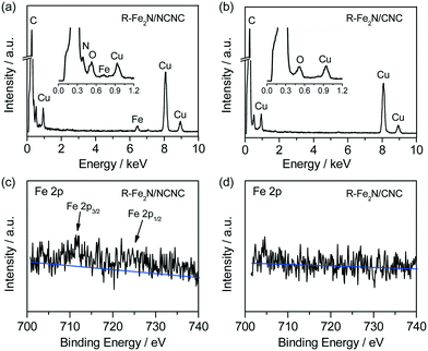 | ||
| Fig. 3 (a and b) EDS and (c and d) XPS spectra of R-Fe2N/NCNC and R-Fe2N/CNC, respectively. Note: in (c), the 2p3/2 peak of Fe species is located at ∼711 eV, corresponding to the ORR-active Fe(III).6e | ||
For the Fe3C-based catalysts, the highly ORR-active species should also be reconsidered similar to the case for the Fe2N-based catalysts. Two Fe3C catalysts were prepared by heating a mixture of the iron source (FeCl2·4H2O), carbon source (polymethylmethacrylate, PMMA), and CNC support with or without a solid nitrogen source (cyanamide, CN2H2) at 800 °C in Ar, denoted as Fe3C–N/CNC and Fe3C/CNC respectively. Two control catalysts, N/CNC and PMMA/CNC, were also prepared by heating a mixture of CNC and PMMA with or without CN2H2, respectively, without an iron source (experimental section).
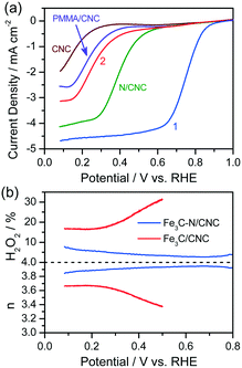
Fig. 4 shows the ORR performance of the catalysts. Fe3C–N/CNC (with a N source in the preparation) presents the highest ORR activity with Eon of 0.920 V, much better than Fe3C/CNC (without a N source in the preparation) with Eon of 0.481 V (Fig. 4a). This catalyst presents a dominant 4e− process with an electron transfer number (n) of 3.90 ± 0.05 and a corresponding H2O2 yield below 8% in the range of 0.08–0.80 V, obviously superior to Fe3C/CNC (Fig. 4b). The ORR performance of Fe3C–N/CNC is located at the top level among the reported Fe3C-based catalysts,9,10 and at the normal level among the Fe/N/C catalysts.11,15 XPS analysis reveals that N species exist in Fe3C–N/CNC while not in Fe3C/CNC. Hence, the high ORR activity of the Fe3C–N/CNC catalyst comes from the Fe-based species with N participation, i.e., the Fe–Nx/C moieties. Even if the Fe3C nanoparticles were removed by acid leaching, the resultant catalyst still shows a high Eon of 0.876 V, also much better than the Fe3C/CNC catalyst without N participation (ESI-5†). The comparison results here indicate that the excellent ORR activity of the Fe3C–N/CNC catalyst with a N source in preparation originates from the Fe–Nx/C moieties, and the Fe3C itself has poor ORR activity.
To get a deep insight into the different activities of Fe–Nx/C, Fe2N and Fe3C species, the density functional theory (DFT) method was employed to calculate their free energy diagrams of ORR.16 Fe–Nx/C was modeled by an Fe–N4 structure in a carbon matrix, denoted as Fe–N4/C.17 Fe2N (010) and Fe3C (001) slabs were chosen for Fe2N and Fe3C (ESI-6†). The free energy diagrams of the ORR process, including the successive steps of O2(g) protonation to OOH*, O–O bond scission of OOH* to O*, O* protonation to OH*, and OH* removal to form H2O, were calculated for all models, as plotted in Fig. 5. The dashed line is the theoretically ideal free energy diagram of ORR, with an equal free energy drop of −1.23 eV for each step.18 As can be seen, the deviations of the free energy diagrams from the ideal one become more and more serious in the order Fe–N4/C < Fe2N < Fe3C. Fe–N4/C possesses the closest profile to the ideal one, indicating the best ORR activity among the three models, while Fe2N holds the second and Fe3C the last. For Fe3C, such a deviation is so huge that the step of OH* to H2O shows a prohibitively high free energy increase of ∼0.785 eV, indicating inert ORR activity. We noted that the step of O* protonation to OH* has the maximum free energy change (ΔG3) either for Fe–N4/C or for Fe2N, which is likely the rate-limiting step around the onset potential (ESI-7†).16 Accordingly, the thermodynamic ORR overpotentials for Fe–N4/C and Fe2N are calculated to be 0.65 and 1.01 V, respectively.16,19 The much lower overpotential of Fe–N4/C suggests the obvious superior activity of Fe–N4/C to Fe2N. Thus it is deduced that the relative order of ORR activities should be Fe–N4/C ≫ Fe2N ≫ Fe3C. Our experimental results fully support this result (ESI-8†).
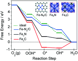 | ||
| Fig. 5 Free energy diagrams of the ORR process for Fe–N4/C, Fe2N and Fe3C. Insets show the corresponding theoretical models. C, grey; N, blue; Fe, purple. | ||
The preceding experimental and theoretical results demonstrate that the high ORR activities of the Fe2N- and Fe3C-based catalysts, which have been intensively studied recently, come from the Fe–Nx/C moieties actually. The Fe3C and Fe2N phases are not the good ORR active sites and are unstable or dissolvable in acidic medium.
In summary, we have designed four typical Fe2N- and Fe3C-based catalysts with or without a solid nitrogen source during the preparation. By structural characterization and systematic comparison of their electrochemical performance, we demonstrate that the high ORR activities of these new catalysts actually originate from the Fe–Nx/C moieties rather than the Fe2N or Fe3C phases themselves. DFT calculations suggest the relative order of ORR activity, i.e., Fe–N4/C ≫ Fe2N ≫ Fe3C, which is in high agreement with our experimental results. The understanding of the ORR active sites of this kind of eye-catching catalyst is significant for exploring advanced Fe-based electrocatalysts.
Acknowledgements
This work was jointly supported by the National Natural Science Foundation of China (No. 51232003, 21373108, 51571110, 21473089, and 21573107), the National Basic Research Program of China (No. 2013CB932902), and Suzhou Science and Technology Plan Projects (No. ZXG2013025).Notes and references
- R. Borup, J. Meyers, B. Pivovar, Y. S. Kim, R. Mukundan, N. Garland, D. Myers, M. Wilson, F. Garzon, D. Wood, P. Zelenay, K. More, K. Stroh, T. Zawodzinski, J. Boncella, J. E. McGrath, M. Inaba, K. Miyatake, M. Hori, K. Ota, Z. Ogumi, S. Miyata, A. Nishikata, Z. Siroma, Y. Uchimoto, K. Yasuda, K. Kimijima and N. Iwashita, Chem. Rev., 2007, 107, 3904–3951 CrossRef CAS PubMed.
- (a) H. A. Gasteiger and N. M. Markovic, Science, 2009, 324, 48–49 CrossRef CAS PubMed; (b) M. K. Debe, Nature, 2012, 486, 43–51 CrossRef CAS PubMed.
- (a) F. Jaouen, E. Proietti, M. Lefèvre, R. Chenitz, J. P. Dodelet, G. Wu, H. T. Chung, C. M. Johnston and P. Zelenay, Energy Environ. Sci., 2011, 4, 114–130 RSC; (b) G. Wu, K. L. More, C. M. Johnston and P. Zelenay, Science, 2011, 332, 443–447 CrossRef CAS PubMed; (c) M. Lefèvre, E. Proietti, F. Jaouen and J. P. Dodelet, Science, 2009, 324, 71–74 CrossRef PubMed.
- (a) T. Sun, Q. Wu, R. C. Che, Y. F. Bu, Y. F. Jiang, Y. Li, L. J. Yang, X. Z. Wang and Z. Hu, ACS Catal., 2015, 5, 1857–1862 CrossRef CAS; (b) J. Qi, L. H. Jiang, Q. Jiang, S. L. Wang and G. Q. Sun, J. Phys. Chem. C, 2010, 114, 18159–18166 CrossRef CAS.
- (a) M. R. Gao, J. Jiang and S. H. Yu, Small, 2012, 8, 13–27 CrossRef CAS PubMed; (b) H. L. Wang, Y. Y. Liang, Y. G. Li and H. J. Dai, Angew. Chem., Int. Ed., 2011, 50, 10969–10972 CrossRef CAS PubMed.
- (a) J. Masa, W. Xia, M. Muhler and W. Schuhmann, Angew. Chem., Int. Ed., 2015, 54, 10102–10120 CrossRef CAS PubMed; (b) G. Wu and P. Zelenay, Acc. Chem. Res., 2013, 46, 1878–1889 CrossRef CAS PubMed; (c) Z. W. Chen, D. Higgins, A. P. Yu, L. Zhang and J. J. Zhang, Energy Environ. Sci., 2011, 4, 3167–3192 RSC; (d) A. Morozan, B. Jousselme and S. Palacin, Energy Environ. Sci., 2011, 4, 1238–1254 RSC; (e) T. Sun, Q. Wu, O. Zhuo, Y. F. Jiang, Y. F. Bu, L. J. Yang, X. Z. Wang and Z. Hu, Nanoscale, 2016, 8, 8480–8485 RSC.
- (a) U. I. Kramm, I. Herrmann-Geppert, J. Behrends, K. Lips, S. Fiechter and P. Bogdanoff, J. Am. Chem. Soc., 2016, 138, 635–640 CrossRef CAS PubMed; (b) U. I. Kramm, M. Lefèvre, N. Larouche, D. Schmeisser and J. P. Dodelet, J. Am. Chem. Soc., 2014, 136, 978–985 CrossRef CAS PubMed; (c) N. Ramaswamy, U. Tylus, Q. Jia and S. Mukerjee, J. Am. Chem. Soc., 2013, 135, 15443–15449 CrossRef CAS PubMed; (d) U. Tylus, Q. Y. Jia, K. Strickland, N. Ramaswamy, A. Serov, P. Atanassov and S. Mukerjee, J. Phys. Chem. C, 2014, 118, 8999–9008 CrossRef CAS PubMed; (e) H. R. Byon, J. Suntivich, E. J. Crumlin and Y. S. Horn, Phys. Chem. Chem. Phys., 2011, 13, 21437–21445 RSC.
- (a) Z. Andrea, V. Goellner, V. Armel, M. T. Sougrati, T. Mineva, L. Stievano, E. Fonda and F. Jaouen, Nat. Mater., 2015, 14, 937–942 CrossRef PubMed; (b) Y. S. Zhu, B. S. Zhang, X. Liu, D. W. Wang and D. S. Su, Angew. Chem., Int. Ed., 2014, 53, 10673–10677 CrossRef CAS PubMed; (c) Q. Y. Jia, N. Ramaswamy, H. Hafiz, U. Tylus, K. Strickland, G. Wu, B. Barbiellini, A. Bansil, E. F. Holby, P. Zelenay and S. Mukerjee, ACS Nano, 2015, 9, 12496–12505 CrossRef CAS PubMed.
- (a) Y. Hu, J. O. Jensen, W. Zhang, L. N. Cleemann, W. Xing, N. J. Bjerrum and Q. F. Li, Angew. Chem., Int. Ed., 2014, 53, 3675–3679 CrossRef CAS PubMed; (b) M. L. Xiao, J. B. Zhu, L. G. Feng, C. P. Liu and W. Xing, Adv. Mater., 2015, 27, 2521–2527 CrossRef CAS PubMed.
- (a) W. X. Yang, X. J. Liu, X. Y. Yue, J. B. Jia and S. J. Guo, J. Am. Chem. Soc., 2015, 137, 1436–1439 CrossRef CAS PubMed; (b) J. Wei, Y. Liang, Y. X. Hu, B. Kong, G. P. Simon, J. Zhang, S. P. Jiang and H. T. Wang, Angew. Chem., Int. Ed., 2016, 55, 1355–1359 CrossRef CAS PubMed; (c) Z. Y. Wu, X. X. Xu, B. C. Hu, H. W. Liang, Y. Lin, L. F. Chen and S. H. Yu, Angew. Chem., Int. Ed., 2015, 54, 8179–8183 CrossRef CAS PubMed; (d) G. Y. Ren, X. Y. Lu, Y. N. Li, Y. Zhu, L. M. Dai and L. Jiang, ACS Appl. Mater. Interfaces, 2016, 8, 4118–4125 CrossRef CAS PubMed; (e) W. X. Yang, X. Y. Yue, X. J. Liu, L. L. Chen, J. B. Jia and S. J. Guo, Nanoscale, 2016, 8, 959–964 RSC; (f) S. Marzorati, J. M. Vasconcelos, J. Ding, M. Longhi and P. E. Colavita, J. Mater. Chem. A, 2015, 3, 18920–18927 RSC; (g) G. Y. Zhong, H. J. Wang, H. Yu and F. Peng, J. Power Sources, 2015, 286, 495–503 CrossRef CAS; (h) X. B. Wang, P. Zhang, W. Wang, X. Lei and H. Yang, Chem. – Eur. J., 2016, 22, 4863–4869 CrossRef CAS PubMed.
- (a) C. Z. Zhu, H. Li, S. F. Fu, D. Du and Y. H. Lin, Chem. Soc. Rev., 2016, 45, 517–531 RSC; (b) Q. Wang, Z. Y. Zhou, Y. J. Lai, Y. You, J. G. Liu, X. L. Wu, E. Terefe, C. Chen, L. Song, M. Rauf, N. Tian and S. G. Sun, J. Am. Chem. Soc., 2014, 136, 10882–10885 CrossRef CAS PubMed; (c) S. Yasuda, A. Furuya, Y. Uchibori, J. Kim and K. Murakoshi, Adv. Funct. Mater., 2016, 26, 738–744 CrossRef CAS; (d) A. G. Kong, X. F. Zhu, Z. Han, Y. Y. Yu, Y. B. Zhang, B. Dong and Y. K. Shan, ACS Catal., 2014, 4, 1793–1800 CrossRef CAS; (e) H. R. Byon, J. Suntivich and Y. S. Horn, Chem. Mater., 2011, 23, 3421–3428 CrossRef CAS; (f) A. Muthukrishnan, Y. Nabae, H. Hayakawa, T. Okajima and T. Ohsaka, Catal. Sci. Technol., 2015, 5, 475–483 RSC; (g) K. Artyushkova, A. Serov, S. Rojas-Carbonell and P. Atanassov, J. Phys. Chem. C, 2015, 119, 25917–25928 CrossRef CAS; (h) J. Tian, L. Birry, F. Jaouen and J. P. Dodelet, Electrochim. Acta, 2011, 56, 3276–3285 CrossRef CAS.
- L. Liu, X. F. Yang, N. Ma, H. T. Liu, Y. Z. Xia, C. M. Chen, D. J. Yang and X. D. Yao, Small, 2016, 12, 1295–1301 CrossRef CAS PubMed.
- (a) S. Chen, J. Y. Bi, Y. Zhao, L. J. Yang, C. Zhang, Y. W. Ma, Q. Wu, X. Z. Wang and Z. Hu, Adv. Mater., 2012, 24, 5593–5597 CrossRef CAS PubMed; (b) K. Xie, X. T. Qin, X. Z. Wang, Y. N. Wang, H. S. Tao, Q. Wu, L. J. Yang and Z. Hu, Adv. Mater., 2012, 24, 347–352 CrossRef CAS PubMed; (c) J. Zhao, H. W. Lai, Z. Y. Lyu, Y. F. Jiang, K. Xie, X. Z. Wang, Q. Wu, L. J. Yang, Z. Jin, Y. W. Ma, J. Liu and Z. Hu, Adv. Mater., 2015, 27, 3541–3545 CrossRef CAS PubMed; (d) Z. Y. Lyu, D. Xu, L. J. Yang, R. C. Che, R. Feng, J. Zhao, Y. Li, Q. Wu, X. Z. Wang and Z. Hu, Nano Energy, 2015, 12, 657–665 CrossRef CAS.
- Y. G. Li, W. Zhou, H. L. Wang, L. M. Xie, Y. Y. Liang, F. Wei, J. C. Idrobo, S. J. Pennycook and H. J. Dai, Nat. Nanotechnol., 2012, 7, 394–400 CrossRef CAS PubMed.
- (a) M. Zhou, C. Z. Yang and K. Y. Chan, Adv. Energy Mater., 2014, 4, 1400840 CrossRef; (b) A. Serov, K. Artyushkova and P. Atanassov, Adv. Energy Mater., 2014, 4, 1301735 CrossRef; (c) D. Zhao, L. J. Shui, C. Chen, X. Q. Chen, B. M. Reprogle, D. P. Wang and D. J. Liu, Chem. Sci., 2012, 3, 3200–3205 RSC.
- (a) J. K. Nørskov, J. Rossmeisl, A. Logadottir, L. Lindqvist, J. R. Kitchin, T. Bligaard and H. Jonsson, J. Phys. Chem. B, 2004, 108, 17886–17892 CrossRef; (b) Y. F. Jiang, L. J. Yang, T. Sun, J. Zhao, Z. Y. Lyu, O. Zhuo, X. Z. Wang, Q. Wu, J. Ma and Z. Hu, ACS Catal., 2015, 5, 6707–6712 CrossRef CAS.
- (a) S. Kattel and G. Wang, J. Phys. Chem. Lett., 2014, 5, 452–456 CrossRef CAS PubMed; (b) S. Kattel, P. Atanassov and B. Kiefer, Phys. Chem. Chem. Phys., 2014, 16, 13800–13806 RSC.
- F. Studt, Catal. Lett., 2013, 143, 58–60 CrossRef CAS.
- (a) J. D. Baran, H. Grönbeck and A. Hellman, J. Am. Chem. Soc., 2014, 136, 1320–1326 CrossRef CAS PubMed; (b) Y. Wang and H. P. Cheng, J. Phys. Chem. C, 2013, 117, 2106–2112 CrossRef CAS.
Footnotes |
| † Electronic supplementary information (ESI) available: Experimental section, additional experimental characterization, and theoretical calculations. See DOI: 10.1039/c6cy01921h |
| ‡ T. Sun and Y. F. Jiang contributed equally to this work. |
| This journal is © The Royal Society of Chemistry 2017 |

