3D printing in chemical engineering and catalytic technology: structured catalysts, mixers and reactors
Cesar
Parra-Cabrera
a,
Clement
Achille
a,
Simon
Kuhn
 *b and
Rob
Ameloot
 *a
*a
aCentre for Surface Chemistry and Catalysis, KU Leuven – University of Leuven, Celestijnenlaan 200F, B-3001 Leuven, Belgium. E-mail: rob.ameloot@kuleuven.be
bDepartment of Chemical Engineering, KU Leuven – University of Leuven, Celestijnenlaan 200F, B-3001 Leuven, Belgium. E-mail: simon.kuhn@kuleuven.be
First published on 13th November 2017
Abstract
Computer-aided fabrication technologies combined with simulation and data processing approaches are changing our way of manufacturing and designing functional objects. Also in the field of catalytic technology and chemical engineering the impact of additive manufacturing, also referred to as 3D printing, is steadily increasing thanks to a rapidly decreasing equipment threshold. Although still in an early stage, the rapid and seamless transition between digital data and physical objects enabled by these fabrication tools will benefit both research and manufacture of reactors and structured catalysts. Additive manufacturing closes the gap between theory and experiment, by enabling accurate fabrication of geometries optimized through computational fluid dynamics and the experimental evaluation of their properties. This review highlights the research using 3D printing and computational modeling as digital tools for the design and fabrication of reactors and structured catalysts. The goal of this contribution is to stimulate interactions at the crossroads of chemistry and materials science on the one hand and digital fabrication and computational modeling on the other.
1 Introduction
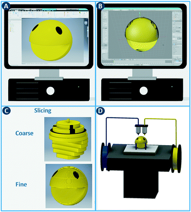
The digital revolution continues to disrupt most sectors, including manufacturing, media, finance, consumer products, healthcare, etc. Computer-aided fabrication technologies, combined with new simulation approaches and data processing capabilities, are changing how we manufacture and customize functional objects. A core concept shared by these digital manufacturing methods is the rapid and seamless transition between a computer model and the physical realization thereof.1 In contrast to fabrication processes that rely on predetermined molds and are optimized for large-volume production of identical objects (e.g. injection molding), digital methods provide significant flexibility, e.g. unique objects tailored to a specific application.The additive manufacturing approaches discussed in this review construct three-dimensional objects by depositing or sintering build material at coordinates derived from a digital model and via a computer-controlled positioning system. All commercialized 3D printing technologies use a layer-based approach, with differences in the materials that can be used, how the layers are created, and how the layers are bonded to each other. The process starts with the design of the model using computer-aided design (CAD) software and exporting it as a printable file format (Fig. 1A and B). This file, which stores information such as coordinates, color and texture, is then sliced into a series of two-dimensional cross sections (Fig. 1C). In the ‘3D printing’ process,2 these slices determine where build material is deposited or sintered. By depositing multiple two-dimensional layers on top of each other, three-dimensional objects can be constructed (Fig. 1D). Note that a balance must be struck between layer thickness, surface finish and printing time. Thinner layers improve the surface finish but increases the printing time considerably.
Many reports in the 3D printing field focus foremost on the comparison with mature fabrication technologies, in terms of the mechanical properties of the produced parts, reproduction fidelity as compared to the digital model, etc. Interdisciplinary studies that validate the benefit of complex 3D printed shapes with computationally optimized geometries in domains such as chemical engineering are much more sparse. Nonetheless, optimized reactor geometries offer significant opportunities in controlling fluid dynamics and temperature uniformity. Moreover, the properties of the materials used for 3D printing are often only discussed in the context of mechanical characteristics, rarely because of their chemical functionality, let alone catalytic activity. Nevertheless, the range of materials that can be printed has expanded considerably over the last decade, now including polymers, ceramics, carbon-based materials and metals, and are relevant as active catalytic sites, catalyst supports and reactor vessels. For these reasons, this review aims to introduce a chemical and chemical engineering dimension in the discussion of additive manufacturing.
Current advances in chemical engineering are often linked to the concept of process intensification,3 which aims to manufacture chemical products in a more sustainable and efficient way. One focus area is to introduce innovative principles in the equipment design leading to improvements in process efficiency. It is our view that the foremost opportunities for process intensification through additive manufacturing lie in continuous flow reactions that make use of heterogeneous catalysts and/or are currently limited by mass, momentum or energy transfer. Nevertheless, more complex scenarios such as non-isothermal reactions or catalysts and reactors dealing with multi-phase flows will likely prove valuable as well. After introducing a number of relevant additive fabrication tools, the potential of these technologies is illustrated through selected recent achievements and suggested future directions.
2 Additive fabrication tools
The additive fabrication toolbox that in our vision will likely have the most profound impact on catalytic technology and chemical engineering consists of extrusion, stereolithography, inkjet printing and powder-based methods (Table 1).2.1 Extrusion-based methods
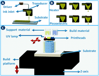
A moveable extrusion head can be used to selectively deposit material to fabricate the slices in the computer model. Robocasting is one implementation of this approach, initially illustrated for the rapid prototyping of ceramics by extruding particle-based pastes. Further development proved the utility for metals, polymers, and composites.4 In the robocasting process, highly concentrated suspensions of the material of interest and a solvent are deposited in a layer-wise fashion through a syringe-type nozzle (Fig. 2A). The process is conceptually similar to icing a cake, with two-dimensional layers of “icing” being stacked to form a three-dimensional object.5 Ensuring proper paste-like consistency of the particle suspension enables shape retention of the deposited lines until drying has taken place. When printing ceramics or metals, the dried object is often fired to remove additives such as viscosity modifiers and to give the part more mechanical stability. The minimum printable feature size in robocasting is typically 30–500 μm.6 Fused deposition modeling (FDM) works in almost exactly the same way, except that in that case a thermoplastic polymer is extruded through a heated nozzle (Fig. 2B). The polymer build material is supplied as a filament that is fed through the nozzle via a pinch roller system. While different build materials can be incorporated in different parts of the object by using more than one extruder in parallel, the transitions between materials are discrete. Moreover, precise spatial can concentration control over chemical functionalization is non-trivial. Nevertheless, a parallel extruder is often used to deposit a sacrificial material to support overhanging structures in the object during the build process. Recently, Oxman and coworkers extended this principle to direct printing of optically transparent glass by operating a printer above the glass melting temperature.7 This method improved the mechanical properties of the print outs when compared to sintering glass particles.2.2 Stereolithography
Stereolithography (SLA) is a 3D printing technique based on the selective solidification of photopolymer resins using an UV light source. As with other 3D printing processes, objects are manufactured by fabricating two-dimensional cross-sections of a computer model, one on top of another. These slices are solidified in a vat of photopolymer resin, either by scanning a laser over the resin surface (Fig. 3A) or by projecting an entire slice (Fig. 3B). The object that is being built rests on a platform that is submersed into the resin vat. The photopolymers used in stereolithography are typically a mixture of epoxides and acrylates, combined with the appropriate photoinitiators. Two of the main advantages of stereolithography over other 3D printing technologies are part accuracy (approx. 25 μm layer thickness) and surface finish. Given the relatively fixed composition of the build resins, this 3D printing approach is not the preferred choice when chemically functionalized parts are required, although post-printing functionalization can in some cases be an option.8 On the other hand, recent advances in resin photochemistry (addition of UV blockers or thermal initiators, mixed photoinitiators, etc.) have improved the resolution in SLA, enabling the printing of structures with internal flow channels without the use of support material. Since the object is constructed in a vat filled with a specific resin, all common stereolithography techniques work with a single build material. For this reason, overhangs in the design are supported by sacrificial break-away scaffolds constructed from the same photopolymer as the main part. Experimental setups enable changing out resin vats during the build process, which results in the combination of multiple materials in a single object, albeit with sharp transitions between the materials and no possibility for mixing materials.8 Stereolithography can be used as well to create ceramic and glass parts by using resins with suspended particles. After creating a green part, burning out the cross-linked polymer binder and sintering the ceramics at high temperature enables the formation of high-quality parts.9,10 The green density must be 50 vol% or higher for adequate sintering. Working with concentrated suspensions can be challenging because of increased light scattering but results in lower part shrinkage during binder burn-out. | ||
| Fig. 3 Stereolithography. (A) Selective photoresin solidification is based on scanning a laser over the surface or (B) by projecting an entire slice (right). | ||
2.3 Inkjet printing
Inkjet printing works by placing tiny droplets of liquid ink at well-defined positions onto a substrate. In this type of printing, pressure pulses are generated based on the digital data sent to the printhead. Each pressure pulse leads to the ejection of a droplet from the printhead (Fig. 4A). Actuation of the pressure pulse is typically realized via a thermal or piezoelectric approach (Fig. 4B). In thermal printheads, the fast and local evaporation of the ink solvent induced by a heat-generating resistor generates a bubble inside the printhead. In piezoelectric systems, the pressure pulse is generated by a mechanical distortion of a piezoelectric actuator due to an applied voltage pulse. Commercial inkjet printers typically deposit droplets of 25 to 125 μm in diameter (8 pL to 1 nL) at high rates, with an optimal resolution of 25 to >100 μm. Although the type of ink that can be printed depends on the geometry and size of the nozzle and the type of actuation. Typical inks are Newtonian fluids with a viscosity <40 cP and surface tension >20 dynes cm−1,11 and to adjust these parameters polymers and surfactants are often added to the formulation. When printing catalysts, either as dissolved precursors or preformed particles, it has to be taken into consideration that these additional components often need to be removed during post-processing.Inkjet printing can be used to build three-dimensional objects in a direct way by depositing droplet patterns on top of each other. Different functional inks can be combined by using multiple inkjet heads in parallel (multijet modeling – MJM), cf. multicolor home office printing. This setup not only enables the deposition of support material but when inks are mutually compatible, materials with graded properties (color, elasticity,…) can be printed by mixing different inks during the build process. Typical build materials for this approach are photopolymers that are cured immediately after deposition by a UV lamp attached to the printhead carriage (Fig. 4C).12 Direct inkjet printing of three-dimensional ceramic13 and metal parts14 has been reported through the use of inks containing ceramic precursors or nanoparticles.15
2.4 Powder bed methods
Powder bed 3D printing methods start by spreading a thin layer of powder (typically around 100 μm thick) across the build area using a counter-rotating leveling roller (Fig. 5A). Object slices are constructed by selectively binding the particles together in the powder layer. When using ceramic powders, powder binding is typically done by moving an inkjet printhead across the build bed to selectively deposit a binder liquid (Fig. 5A). In a variation of this method, a dry binder is mixed with the build powder and a binder activator is printed. The unbound powder material serves as a support for the object under construction and can be recycled for the next build. The minimum feature size of this binder printing process depends on the particle size but is typically around 100 μm.1 In combination with the right binder, almost any powder with a particle size in the 10–40 μm range can be used. As a rule of thumb, the minimal height of each layer (z-resolution) is about three times the average particle size. In printed ceramics, the object is often fired after evaporation of the binder liquid to sinter the particles together. For metal and polymer powders, a laser beam can be used instead of a binder printhead to fuse the particles together by partial or complete melting. For metals and some polymers (e.g. nylon) these selective sintering (SLS)/melting (SLM) processes are the dominating 3D printing technology (Fig. 5B). | ||
| Fig. 5 Powder bed 3D printing methods. (A) 3D printing via binder deposition on a powder bed. (B) 3D printing via selective sintering on a powder bed. | ||
| Technology | Layer thickness | Typical materials | Comments |
|---|---|---|---|
| Extrusion-based | FDM: 50–300 μm | Polymers | Typical thermoplastics are ABS,PLA, PC, PP, etc. Each polymer has a different chemical and thermal stability. Hybrid polymers were reported to improve the poor properties of polymers, e.g. composites with metal oxides or graphene.16,17 |
| Robocasting: 30–500 μm | Ceramics and metals | Concentrated suspensions of a wide range of materials can be formulated as a viscous paste that keeps its shape after extrusion. The printed object is often fired to remove additives. | |
| Stereolithography | 1–50 μm | Photoresins | Acrylate or epoxy-based resins are typically used. |
| Ceramics | Stereolithography resins with suspended ceramic or glass particles enable the fabrication of green parts. Burning out the cross-linked polymer binder and sintering the ceramics enables the formation of high-quality ceramic parts.9 | ||
| Inkjet printing | 1–50 μm | Photoresins | Acrylate or epoxy-based resins are typically used. |
| Ceramics and metals | Direct inkjet printing of ceramic and metal parts is possible using inks containing ceramic precursors or nanoparticles followed by sintering. | ||
| Powder-based | Binder inkjetting: 100–150 μm | Polymers | A wide range of polymers are used for binder jetting: PMMA, PP, PS, etc. For SLS thermoplastics are used: Nylon 11, Nylon 12, PEEK, etc. The materials are generally stable at high temperatures. As for all powder-based methods, the removal of the unsintered powder might be challenging. |
| SLS: 20–150 μm | Ceramics | Typical materials include alumina, zirconia and carbides. | |
| SLM: 20–150 μm | Metals | Typical materials for SLM are stainless steel, titanium, aluminum, etc. The metals are stable to high temperatures and resistant to a range of chemical solutions. | |
3 Modeling tools
Since additive manufacturing enables the rapid transition between a computer model of an object and the fabrication thereof, an interesting opportunity is the combination of the fabrication tools highlighted in the previous section with computational optimization. This section provides a short description of the modeling tools used in chemical engineering to characterize transport phenomena in flowing systems. First, the use of computational fluid dynamics (CFD) is introduced to characterize hydrodynamics, heat and mass transfer in continuous flow mixers and reactors. To describe the added complexity of structured heterogeneous catalysts in continuous flow reactors, the concept of multiscale modeling is discussed to couple solid surface catalyzed reactions with CFD.3.1 Computational fluid dynamics
CFD is a branch of fluid mechanics that uses numerical analysis to solve fluid flow problems. While CFD was initially driven by aerodynamics, it is now widely applied, to geophysical flows, in the automotive industry, and to industrial manufacturing.18 In chemical engineering, CFD involves the numerical solution of conservation equations for mass, momentum and energy in a flow geometry of interest. An application example is the study of flow hydrodynamics at different flow rates in three different reactors, namely the 1st and 2nd generation Corning Advanced Flow Reactor (Gen 1 AFR, Gen 2 AFR), and the Low Flow Reactor (LFR) (Fig. 6A–C).19 CFD shows that when a threshold flow rate is exceeded, recirculation zones are observed that are especially pronounced in the Gen 1 AFR (Fig. 6B). When solving for the transport of a solute, CFD allows to quantify the residence time distribution (RTD) of each reactor in addition to the description of fluid flow. For the Gen 2 AFR and the LFR symmetric curves with a small degree of dispersion (i.e. close to ideal plug flow behavior) are found, whereas the Gen 1 AFR design exhibits asymmetry that can be explained by the previously mentioned flow recirculation. This example highlights the capability of CFD in design optimization by modeling the hydrodynamics of flow reactors.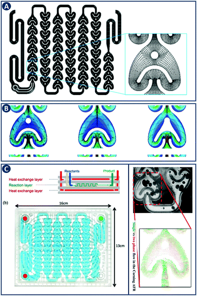 | ||
| Fig. 6 CFD application example in comparing flow reactor geometries. (A) Representation of the Gen 1 AFR flow channel. The inset provides details of the computational mesh. (B) Velocity field and corresponding streamlines in the Gen 1 AFR (left), Gen 2 AFR (middle) and the LFR (right) for a flow rate of 40 mL min−1. Flow recirculation and potentially stagnant fluid zones are visible in the Gen 1 AFR between the post and the U-shaped structure. Panels A and B reproduced from ref. 19 with permission from American Chemical Society, copyright 2015. (C) Left: Corning AFR module. Right: Velocity vectors of single and two-phase flow. Reproduced from ref. 20 with permission from American Chemical Society, copyright 2015. | ||
The governing equations describing the conservation of mass, momentum and energy are not scale-dependent and can therefore be applied to a wide range of problems and length scales, from micro-reactors to large scale systems. Optimizing the hydrodynamics inside flow reactors is crucial as it directly affects the mass and heat transfer. The flow regime can be controlled by different variables including the shape of the channel, the contact angle of the internal walls, the mixer structure, fluid phase (single or multiple), and conditions (flow velocities, temperature, etc.). The effect of each of these parameters and their relative importance can be captured with CFD, and this knowledge can be coupled with experimental studies for further design analysis. As an example, Kuhn and coworkers characterized the hydrodynamics of the Corning Gen 1 AFR, focusing on the differences of single-phase (liquid) versus two-phase (gas–liquid) flow. They concluded, that including the gas phase leads to a more uniform distribution of velocity fluctuations and increased transport processes (Fig. 6C).20
The equations describing flow and transport phenomena are given by the conservation of mass, ρ, momentum, ρui, thermal energy, ρcpT, and species Ci. Considering the single-phase flow of Newtonian fluids with constant density ρ (i.e. incompressible fluids) and constant dynamic viscosity μ, the conservation of mass and momentum can be written21 as the continuity equation
 | (1) |
 | (2) |
 | (3) |
 | (4) |
 with the heat capacity cp and the thermal conductivity λ. Ci denotes the molar concentration of species i of diffusivity Di, and Ri represents the volumetric rate of generation (or consumption) of component i.
The presence of the convection term in each equation highlights the link between the hydrodynamics and the involved transport processes. As demonstrated above, the use of CFD allows to characterize the fluid dynamics inside a reactor, which allows to optimize the associated mass and heat transfer as these processes are coupled to the fluid flow.
To solve above equations, several commercial software packages exist that are either based on the Finite Element Method (FEM, e.g. COMSOL) or the Finite Volume Method (FVM, e.g. Ansys Fluent). The major difference between these two CFD approaches is that in FEM the geometry is discretized by finite elements interconnected at nodal points, whereas in FVM the geometry is subdivided into finite volumes enclosing the nodal points of the mesh. As a result, FVM is a robust method to compute hydrodynamics and associated transport phenomena. On the other hand, FEM is better suited to solve coupled multiphysics problems involving several domains, e.g. fluid–structure interaction to capture the dynamic distortion of a stirrer in a shear field, or the coupling between applied acoustic pressure (ultrasound) and induced fluid motions (streaming).
In addition to describing fluid flow in a known geometry, CFD is capable as well to perform shape-based optimization. This development was driven by the aerodynamics industry to computationally improve wing design to reduce fuel consumption. Starting from a pre-defined starting geometry and the corresponding CFD results, the solver is allowed to perform parametric changes to this geometry in order to optimize an objective function (e.g. to minimize pressure drop). The resulting optimized ‘digital geometry’ is not necessarily easy to accurately fabricate through traditional machining methods. Additive manufacturing will be able to close this gap between digital geometry and physical object. The interplay between these new fabrication tools and CFD will allow to introduce design modifications to address all transfer problems independently.
3.2 Multiscale modeling tools
Since CFD is able to predict heat and mass transfer in the bulk of the fluid, the above simplified equation can be readily applied for the kinetic modeling of microreactors where the reaction takes place in the bulk of the fluid. However, when the reaction takes places on the surface of a heterogeneous catalyst, detailed surface and fluid-phase reaction mechanisms must be considered. A multiscale modeling approach is therefore required, to capture the different length- and time-scales of species transport in the bulk fluid, adsorption on a catalytic surface and the subsequent chemical transformation. These individual steps can be implemented via empirical kinetic models. Examples are power-law kinetics that makes use of effective rate constants fitted to experimental data or Langmuir–Hinshelwood–Hougen–Watson models that make use of more detailed surface reaction mechanisms. However, due to their empirical nature, multiple rate expressions can be fitted to the same set of experimental data, and the extracted parameters may be physically unrealistic. In light of these limitations, microkinetic modeling has been developed which relies on a detailed description of the different reaction steps on the catalyst surface. The application of these different multiscale modeling approaches with respect to metal-catalyzed reactions has been reviewed by Salciccioli et al.22The challenge in the multiscale modeling approach lies in the structural difference of models across scales. In CFD, the fluid flow is treated as a continuum, i.e. the movement of individual molecules is neglected, and only the bulk movement is captured. However, the physical and chemical processes on the catalyst surface need to be treated in a discrete manner, resolving individual molecules and capturing stochastic events with certain probabilities. Most models address this issue through a one-way coupling, by passing parameters extracted from the molecular scale model to the larger continuum scale.22 Furthermore, when molecular modeling (e.g. molecular dynamics or kinetic Monte Carlo) is used to represent the chemical transformations, the simulations are restricted to limited time and length scales. This limitation entails that modeling an entire process with its associated time and length scale would require excessive computational resources. The common approach to alleviate these issues is to restrict the use of molecular simulations to determine parameters that can be coupled to macroscopic approaches like CFD.23 As discussed in more detail in Section 5.2, these coupled approaches allow to describe and to design structured catalysts for use in continuous flow systems.
4 Reactors and mixers
In contrast with other manufacturing methods, 3D printing enables to fabricate geometrically optimized reactors. The shape of conventional reactors is to a large extent determined by their manufacturing cost and/or the limitations of conventional manufacturing methods (e.g. cylindrical shape). While often adequate for batch chemistry, although depending on the stirring mode, commonly available reactor shapes may not fully realize the potential of continuous flow processes. The use of small-scale continuous flow reactors, with channel cross sections ranging from tens of microns to a few millimeters, increased rapidly over the past two decades. Because of the fast mixing and efficient heat and mass transfer in such flow reactors, a high level of control over reaction parameters is possible.24 Furthermore, the small volume of the reactor improves the safety of the process, since ultrafast and exothermic reactions including highly unstable intermediates can be performed.25 Moreover, although custom small-scale batch reactors will increase the time- and cost effectiveness of lab-scale work, fully or partially 3D printed continuous flow reactors will likely have a more profound impact because of their scalability up to industrial production via parallelization. For instance, Adamo et al. developed a plug-and-play platform to study the continuous-flow synthesis and formulation of active pharmaceutical ingredients. The system produces sufficient quantities per day to supply up to thousands of doses meeting the U.S. Pharmacopeia standards (Fig. 7A).26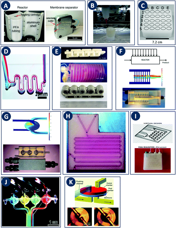 | ||
Fig. 7 Flow microreactor and micromixers. (A) Left: PFA (polyfluoroalkoxy) tube flow reactors. Right: Separation unit. Reproduced from ref. 26 with permission from American Association for the Advancement of Science, copyright 2016. (B) Left: Completed acetoxy-silicone-based reactionware ready to be removed from the printer. Right: Reactor-geometry-controlled synthesis. In reactor (1), two equivalents of 5-(2-bromoethyl)phenanthridinium bromide solution can mix with a p-methoxy aniline solution, thus allowing complete oxidation to C22H19BrN2O with a yield of 90%, whereas the smaller volume of reactor (2) constrains the stoichiometry to 1![[thin space (1/6-em)]](https://www.rsc.org/images/entities/char_2009.gif) : :![[thin space (1/6-em)]](https://www.rsc.org/images/entities/char_2009.gif) 1, allowing the isolation of the unoxidized C22H20N2O species in an 80% yield. Reproduced from ref. 30 with permission from Nature Publishing Group, copyright 2012. (C) High-throughput solvothermal reactor. Reproduced from ref. 31 with permission from WILEY-VCH Verlag GmbH & Co. KGaA, Weinheim, copyright 2014. (D) Transparent and inert 3D printed millifluidic mixer. Reproduced from ref. 34 with permission from Royal Society of Chemistry, copyright 2016. (E) Split-and-recombine mixers. Top: Printed by FDM and ABS as material. Middle: Printed by SLA and Accura 60 photoresin as material. Bottom: Printed by SLM and stainless steel as material. Reproduced from ref. 32 with permission from Royal Society of Chemistry, copyright 2013. (F) Ideal distributed dosing in a continuous reactor. Top: Schematic representation. Middle: Simulation of product distribution. Bottom: Prototype reactor with distributed continuous dosing. (G) Top: Fluid dynamics simulation of the distribution of desired component in one three-dimensional unit cell of a NETmix reactor. One mixing chamber with two inlets and two outlets is shown. Bottom: Prototype photoresin and metal NETmix reactors with three successive chambers. The solutions were inflow at 32 mL min−1, resulting in a residence time of 30 s. Panels F and G reproduced from ref. 38 with permission from SINTEF Materials and Chemistry, copyright 2015. (H) Millifluidic devices tailored to a specific reaction, the channels in the device have been filled with a methanol solution of rhodamine B dye to render them visible. Reproduced from ref. 39 with permission from Royal Society of Chemistry, copyright 2012. (I) PLA version of an 1 mL flow reactor, with a channel diameter of 1.59 mm. Reproduced from ref. 40 with permission from WILEY-VCH Verlag GmbH & Co. KGaA, Weinheim, copyright 2017. (J) Inkjet-printed microfluidic transistor for multiflow control. Reproduced from ref. 44 with permission from Royal Society of Chemistry, copyright 2015. (K) 3D printed membrane valve. Schematic illustration and microscope photos. Bottom left: Open valve. Bottom right: Closed valves. Reproduced from ref. 45 with permission from Royal Society of Chemistry, copyright 2016. 1, allowing the isolation of the unoxidized C22H20N2O species in an 80% yield. Reproduced from ref. 30 with permission from Nature Publishing Group, copyright 2012. (C) High-throughput solvothermal reactor. Reproduced from ref. 31 with permission from WILEY-VCH Verlag GmbH & Co. KGaA, Weinheim, copyright 2014. (D) Transparent and inert 3D printed millifluidic mixer. Reproduced from ref. 34 with permission from Royal Society of Chemistry, copyright 2016. (E) Split-and-recombine mixers. Top: Printed by FDM and ABS as material. Middle: Printed by SLA and Accura 60 photoresin as material. Bottom: Printed by SLM and stainless steel as material. Reproduced from ref. 32 with permission from Royal Society of Chemistry, copyright 2013. (F) Ideal distributed dosing in a continuous reactor. Top: Schematic representation. Middle: Simulation of product distribution. Bottom: Prototype reactor with distributed continuous dosing. (G) Top: Fluid dynamics simulation of the distribution of desired component in one three-dimensional unit cell of a NETmix reactor. One mixing chamber with two inlets and two outlets is shown. Bottom: Prototype photoresin and metal NETmix reactors with three successive chambers. The solutions were inflow at 32 mL min−1, resulting in a residence time of 30 s. Panels F and G reproduced from ref. 38 with permission from SINTEF Materials and Chemistry, copyright 2015. (H) Millifluidic devices tailored to a specific reaction, the channels in the device have been filled with a methanol solution of rhodamine B dye to render them visible. Reproduced from ref. 39 with permission from Royal Society of Chemistry, copyright 2012. (I) PLA version of an 1 mL flow reactor, with a channel diameter of 1.59 mm. Reproduced from ref. 40 with permission from WILEY-VCH Verlag GmbH & Co. KGaA, Weinheim, copyright 2017. (J) Inkjet-printed microfluidic transistor for multiflow control. Reproduced from ref. 44 with permission from Royal Society of Chemistry, copyright 2015. (K) 3D printed membrane valve. Schematic illustration and microscope photos. Bottom left: Open valve. Bottom right: Closed valves. Reproduced from ref. 45 with permission from Royal Society of Chemistry, copyright 2016. | ||
In the context of industrial production, the final size of a flow reactor channel or a structured heterogeneous catalyst (see next section) is mainly determined by the desired throughput. However, there is limit to scaling up reactor dimensions because although reaction kinetics are not changing with reactor size, all physical processes (i.e. heat and mass transfer) are scale-dependent.27 As such, following a pure scale-up approach will be penalized by transport limitations, and consequently reduced conversion and yield. The severity of these effects depend on a number of reaction-specific parameters, including kinetics, the reaction order, the reaction enthalpy, etc. Because of these reasons, successful examples of scale-up rely on a combination of scale-up and scale-out, i.e. increasing the reactor size to an optimum dimension and subsequent numbering up to achieve the desired reaction volume. This optimum size will depend on the considered reaction media and conditions, but a value in the order of 10 mm is often encountered in commercial systems targeting pharmaceutical or fine chemistry products,28,29 which therefore also represents the target size for any digital fabrication technique. However, since many commodity chemicals are produced in a continuous fashion through large-scale ‘flow chemistry’ (ammonia, petrochemical products, etc.) opportunities for process intensification by combining modeling and additive manufacturing might also emerge at a much larger scale. In such cases, directly 3D printing reactors with dimensions that match the required throughput is not yet (economically) feasible. Nevertheless, a feasible strategy could be to improve the performance of conventional reactor layouts through optimized 3D printed internals.
When combining multiple reactants or phases in a flow reactor, the internal structure needs to realize the desired mixing regime. A successful strategy has been to incorporate packed beds of particles or open-cell foams as static mixers in the reactor channel. Since the flow regime in such porous media is not well understood, in terms of laminar versus turbulent behavior, concentrated modeling efforts exist in this field. These theoretical studies will prove valuable in the computational optimization of 3D printed static mixers. Note that even though such porous reactor internals can be ideal supports for heterogeneous catalysts, the cases highlighted in this section exclusively concern non-catalytic and homogeneously catalyzed reactions. Nevertheless, considerations regarding flow in foam-like structures and packed granular beds will be equally relevant in the discussion of structured catalysts.
4.1 Fabrication and testing
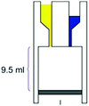
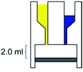
Even though we believe that in the future many more 3D printed flow reactors will appear, batch reactors were the first examples of bespoke reaction vessels. Cronin and coworkers demonstrated how a judicious choice of polymer build materials enables the direct use of custom 3D printed reactors termed ‘reactionware’. For instance, they demonstrated how reaction vessels could be printed via robocasting a quick-curing acetoxysilicone polymer (Loctite 5366 bathroom sealant) and inserting non-printable components (glass frits, viewing window, etc.) during pre-programed pauses in the printing schedule.30 The difference between the reactor volumes in the design software and the printed chambers was within a 5% error margin. Although commercial alternatives exist for the resulting elastomer batch reactors, they are much more expensive and/or lack the rapid design iterations enabled by digital fabrication and needed to optimize synthesis protocols. The reaction of 4-methoxyaniline and 5-(2-bromoethyl)-phenanthridinium bromide was used to illustrate the effect of reaction chamber design. The composition of the reacting mixture was controlled by setting the mixing chamber volume, and thereby the volume and ratio of both reactant solutions that could mix before filling up the chamber. Interestingly, this approach resulted in a reversal of selectivity for the obtained product (Fig. 7B, Table 2A and B). Another example of a custom batch reactor used to streamline a synthetic workflow in the lab is a high-throughput reactor 3D printed in polypropylene via fused deposition modeling (Fig. 7C).31 Cronin and coworkers exploited the chemical resistance of this polymer to perform high-throughput optimization of solvothermal reactions in arrays tailored to the required volumetric capacity, at temperatures up to 140 °C and for periods upwards of 72 h.| Reaction | Reaction type | Conditions | Reactor type | Ref. |
|---|---|---|---|---|
(A)
|
Synthesis of an imidazopyridine derivative |
– Solvent: d6-DMSO
– Reaction chamber of 9.5 mL – Mixing induced by vacuum – Room temperature – >90% conversion, time: 21 h |
 – Batch – Batch
– 3D printing technique: robocasting – Printing material: acetoxysilicone polymer |
Symes et al.30 |
(B)
|
Synthesis of an imidazopyridine derivative |
– Solvent: d6-DMSO
– Reaction chamber of 2.0 mL – Mixing induced by vacuum – Room temperature – 80% conversion, time: 21 h |
 – Batch – Batch
– 3D printing technique: robocasting – Printing material: acetoxysilicone polymer |
Symes et al.30 |
(C)
|
Persulfate-iodide reaction |
– Solvent: water
– Flow rates: 18–40 mL min−1 – Room temperature – Reaction times 210–360 s |
 – Flow – Flow
– 3D printing technique: SLA – Printing material: Accura 60 resin |
Capel et al.32 |
(D)
|
Solvothermal synthesis of a metal–organic framework |
– Solvent: ethanol
– Flow rate: 32 mL min−1 – Temperature: 82 °C – Residence time: 30 s – Crystallinity of the product confirmed, no impurities. |
 – Flow – Flow
– 3D printing technique: SLA (top) and SLM (bottom) – Printing material: acrylate resin (top) and stainless steel (bottom) |
Grande et al.38 |
(E)
|
Imine synthesis |
– Solvent: methanol
– Flow rates: 10–200 μL min−1 – Full conversion at 10 μL min−1 |
 – Flow – Flow
– 3D printing technique: FDM – Printing material: polypropylene (PP) |
Kitson et al.39 |
(F)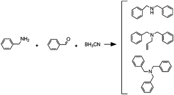
|
Reductive amination followed by an alkylation reaction |
– Solvent: methanol
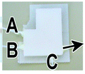
– Flow rates: 2.5 μL min−1 (A), 5 μL min−1 (B) and 7.5 μL min−1 (C). – Full conversion, time: 42 min |
 – Flow – Flow
– 3D printing technique: FDM – Printing material: polypropylene (PP) |
Kitson et al.39 |
(G)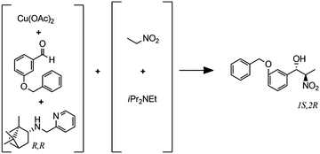
|
Enantioselective copper-catalyzed Henry reaction |
– Solvent: EtOH
– Flow rates: 0.033–0.2 mL min−1 – Temperatures: 25, 0 and −20 °C – Best result: −20 °C, 30 min, 72% yield and 87% ee for the major anti isomer. |
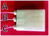 – Flow – Flow
– 3D printing technique: FDM – Printing material: polylactic acid (PLA) |
Rossi et al.40 |
Capel et al. thoroughly tested common 3D printing techniques in the context of flow chemistry and highlighted the strengths and weaknesses of each process.32 The compared fabrication methods clearly differ in terms of chemical and thermal stability of the build materials, engineering and design limitations and achievable build resolution. SLA and MJM have the best resolution (<50 μm), allowing narrow flow paths and complex internal structures. However, the available build materials are limited, typically acrylate or epoxy photopolymers with relatively poor chemical and thermal stability. These photopolymers degrade and swell in strong solvents and usually have a glass transition temperature below 100 °C. In MJM a sacrificial wax-like support material is printed to create internal cavities. The removal of this support by dissolution is diffusion-limited and might be slow for narrow and complex channels. In SLA, internal channels can be created without support by precisely controlling the curing time for the channel ‘roof’, potentially aided by light-adsorbing additives that decrease the solidification time.33 The uncured liquid resin inside the channels is readily removed with compressed air. Recent advances in the photochemistry of resins (e.g. UV blockers, photoinitiators, thermal initiators) have improved the resolution in SLA. However, together with the internal surface roughness resulting from overcuring, these chemicals can lower the transparency of the printed reactors. When monitoring of the chemical reaction in the channel interior is desired, direct optical access is a major advantage. In this context, Folch and coworkers avoided the potential issues with resin-only reactors by printing fully transparent millifluidic devices between two glass surfaces (Fig. 7D).34 FDM has been used to print a wide range of thermoplastics (ABS, PC, PLA, PP, etc.) with different chemical and thermal stabilities, but suffers from a relatively low resolution (50–100 μm). Materials like ABS have a glass transition of 220 °C, while PC has a lower glass transition 147 °C. Some of the more chemically resistant thermoplastics such as polypropylene (PP) are notoriously prone to warping in FDM. To create internal cavities in an FDM print, either support material or fast extrusion of ‘bridging’ layers can be used. FDM fabrication of reactor channels can be challenging because of resolution limitations and since the interlayer bonding can be weak which leads to poor sealing. Powder-based methods (SLS, SLM) offer a wide selection of materials that can be stable at high temperatures and resistant to a range of chemicals: polymers (Nylon, PP, PEEK), ceramics and metals (steel, titanium, etc.).32 In powder-based technologies, the unbound powder acts as support material for the channels during printing. However, cleaning-up the un-sintered powder might be challenging and time-consuming for complex geometries. For instance, in the SLM fabrication of a stainless steel flow reactor with channels as small as 1 mm, it was found that unwanted partial melting of the loose build material in the channels led to a blockage (Fig. 7E bottom, Table 2C). In addition, printing of leak-proof dense channel walls is non-trivial for many powder types.
Despite the above challenges, some 3D printed flow reactors and mixers have been demonstrated. Especially interesting in tailoring flow reactors to a particular reaction is the seamless transition between a CFD-optimized reactor geometry and the digital fabrication thereof. Tailoring the design of static mixer reactors to improve performance is an excellent illustration of this concept.35 For instance, a NETmix reactor is based on a network of interconnected mixing chambers, each with multiple inlets.36,37 It was found that this setup is ideally suited to perform reactions with complex and fast kinetics, where mixing quality and intensity are critical. Computational optimization of the reactor layout for the reactive crystallization of an organic–inorganic hybrid material resulted in a configuration of the inlet and outlet channels that could not be realized in an in-plane format. Grande and coworkers printed the optimal three-dimensional design in one piece in photoresin, stainless steel and titanium and successfully tested the reactors in continuous flow operation (Fig. 7F).38 Notably, the steel reactor was able to withstand a pressure of 80 bar. The same team also illustrated the possibility of realizing an ideal distributed flow via 3D printing, to achieve a high degree of micromixing and perform fast reactions.38 While distributed dosing as depicted in Fig. 7G (top panel), is often hard to realize in conventional reactors, it becomes almost trivial via fluid dynamics optimization combined with digital fabrication (Fig. 7G, middle and bottom, Table 2D). In a different example, Kitson et al. managed the warping of PP and FDM-printed ‘reactionware’ with a geometry tailored to specific reactions: organic synthesis of an amine by two-step reductive amination, and subsequent alkylation of the resulting secondary amine; the inorganic synthesis of large polyoxometalate clusters; and the controlled synthesis of gold nanoparticles (Fig. 7H, Table 2E and F).39 Recently, Benaglia and coworkers fabricated flow reactors using FDM and different polymers, polylactic acid (PLA), high impact polystyrene (HIPS) and Nylon.40 The 3D printed flow reactors were tested for a catalytic stereoselective Henry reaction. Biologically active targets, such as: norephedrine, metaraminol and methoxamine, were synthesized in a two-step continuous-flow process inside the customizable reactors. (Fig. 7I and Table 2G). Capel et al. designed, fabricated and tested different flow reactors for oxidizing an aldehyde to a methyl ester.32 The first design was a split-and-recombine mixer (Fig. 7E top) with a channel diameter of 3 mm and a volume of 3.6 mL. However, when FDM-printed in ABS, the reactor had numerous leaks. In an iteration, SLA in combination with commercially available resin (Accura 60 from 3D Systems) was used to print reactors with internal volumes and channel diameters ranging from 16.4 mL to 23 mL and 0.25 mm to 3 mm, respectively (Fig. 7E middle).
Apart from optimizing the reactor geometry and inlet positions, another approach to intensify mixing-limited reactions or to achieve plug flow behavior is to insert porous structures into the flow channel.41 Experimental results indicate that compared to packed beds, foam structures with a higher porosity enhance mass transfer equally well, but at a considerably lower pressure drop. Such foam static mixers therefore result in a lower energy consumption and are an example of process intensification.42 With the advent of additive manufacturing, precise fabrication of designer porous inserts becomes possible. For instance, Potdar et al. observed enhanced mixing and an order of magnitude reduced energy dissipation for foam-like robocast flow reactor inserts compared to packed particle beds.43
Optimization of flow reactors through additive manufacturing is not limited to passive elements. 3D printing allows to directly integrate active flow control components such as valves before, after or inside the main reactor chamber. Especially at the small scale it could be beneficial to include such control operators in a fully automated and integrated microreactor. Sochol et al. used MJM to manufacture control operators with complex geometries, including fluidic analogues of capacitors, diodes and transistors (Fig. 7J).44 These fluidic operators have a diaphragm that deforms in response to an input pressure, thereby allowing or blocking the flow. A combined theoretical and experimental approach was used to tune the control parameters for each device. Furthermore, Nordin and coworkers presented a high-density SLA-printable microfluidics with active components such as valves and pumps. The key component in these devices is a 20 μm thick membrane valve sandwiched between two cylindrical voids (Fig. 7K). When no pressure is applied the valve is open and solution can flow between the channels. The devices can perform a serial multiplexing, and the combination of five valves enables operation as a mixer working at flow rates as high as 40 μL min−1.45
4.2 Modeling and characterization
As highlighted earlier, CFD can be used in design optimization studies to improve the hydrodynamics of flow reactors. For the simulation of single-phase flow in micro- and milli-scale reactors based on a flat plate or capillary design CFD is established as a standard tool. However, CFD of more complex cases such as multiple phases and/or complex geometries (e.g. random porous media) are still an active area of research. For instance, while the flow in common micro- and milli-scale reactors is predominantly laminar, the prevailing flow regime in random porous media is less clear, with the onset of turbulence inside the pores still an open question.46–48 One criterium to estimate the flow regime is based on the pore Reynolds number49 Rep | (5) |
Different CFD approaches exist to simulate turbulent flows in porous media, which differ in their computational demands and resolution in terms of the turbulent length and time scales they resolve. The computationally most expensive method is direct numerical simulation (DNS), which resolves all length and time scales in the turbulent flow and does not introduce any additional modeling. Therefore, DNS require short time-steps and a fine computational grid, resulting in extensive simulation times for large Reynolds numbers and realistic geometries. Hence, DNS of porous media flow is only applied in limited cases (e.g. generic pore geometry and limited Rep). Another approach is large-eddy simulation (LES), which resolves the large-scale turbulent motions present in the flow, and only needs modeling to represent the influence of the flow structures smaller than the grid size. Therefore, LES can be applied to a wide range of Reynolds numbers and geometries at a reasonable computational cost. The most cost-effective turbulence models are based on the Reynolds-averaged Navier–Stokes equations (RANS), as they only solve for the mean fluid motion, and the turbulent contributions are captured by additional model equations. This also means that RANS models do not resolve the wall boundary layer, but use pre-defined wall functions to describe the near-wall velocity field. However, these wall functions are developed for rather generic cases, and their application to complex geometries as porous media can lead to deviations in the results.
Early CFD approaches of flow in porous media focused on flow and heat transfer in tetrakaidecahedral foams (Fig. 8A). Boomsma et al. performed a steady-state simulation of water flowing through such a unit cell employing periodic boundary conditions at a Rep of 170.52 Experiments on aluminum foams of similar structure revealed a pressure drop 25% lower compared to the simulations, which was explained by wall effects (e.g. surface roughness not accounted for in the simulation). A body-centered-cubic (BCC) structure with a spherical unit cell was studied by Krishnan et al. through a DNS including heat transfer at Rep < 100 using water and air as working fluids.53 The calculated pressure drop and heat transfer coefficients showed a good agreement with experimental measurements and semi-empirical models for porosities >94%, arguably because the absence of turbulence at relatively low Rep. This work was extended to simulations of three different unit-cell geometries (Fig. 8A).54 The permeability of the structures was chosen as the characteristic length scale and Rep 0.01–10 based on permeability. As in the earlier study, the pressure drop and heat transfer coefficients agreed with experiments and semi-empirical models for porosities >80%. Annapragada et al. applied DNS to the same three unit-cell geometries with Rep ranging from 0.01–10.55 In addition, the unit-cell geometries are numerically deformed under uniaxial loads using a finite-element method, which is an often observed phenomena in foam-like structures. A corrected model for the permeability of compressed foams as a function of strain for flows transverse to the direction of compression was proposed.
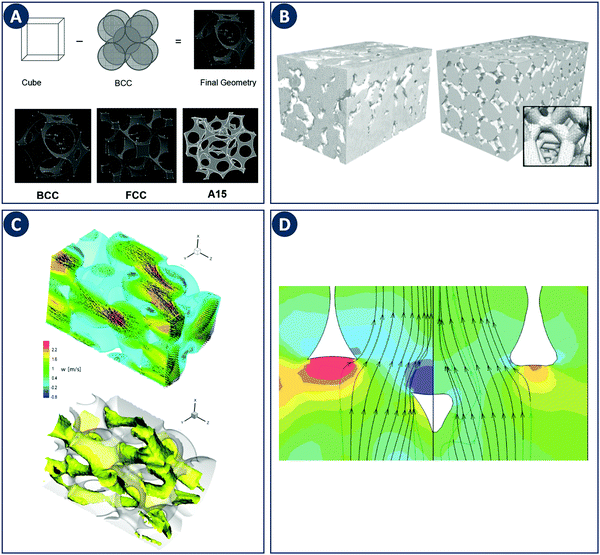 | ||
| Fig. 8 Examples of modeling of foam-like structures. (A) Top: Schematic representation of the foam geometry creation by subtraction of sphere packings. Bottom: Sample foam geometries representing BCC, FCC, and A15 arrangements of spherical pores. Reproduced from ref. 55 with permission from Informa UK Limited, copyright 2008. (B) Comparison of the computational grid based on a MRI scan of a commercial ceramic foam (left) with a “random” foam based on tetrakaidecahedrons (right). Reproduced from ref. 57 with permission from WILEY-VCH Verlag GmbH & Co. KGaA, Weinheim, copyright 2008. (C) Representation of turbulent flow through a streamwise-periodic porous structure. The top image shows the velocity field for two different planes with the contour plot of the streamwise velocity component in the background. The bottom image shows the isosurface of the streamwise velocity component at a value of 1.2 m s−1. (D) Difference in streamlines with respect to the ligament shape. The relative pressure is depicted as contour plot in the background. Panels C and D reproduced from ref. 58 with permission from Elsevier Ltd, copyright 2010. | ||
Simulations of more realistic structures than the idealized foams discussed above have been enabled by Magnetic Resonance Imaging (MRI). von der Schulenburg et al. considered a porous structure consisting of packed polyurethane foam cubes.56 Simulations were compared to the pore-scale velocity obtained by MRI and the effect of foam compression on the flow field was successfully modeled. Habisreuther et al. compared laminar flow simulations (Rep 3–373) in a “random” tetradecahedral foam with a geometry obtained from MRI of a commercial ceramic foam (Fig. 8B).57 Compared to experimental measurements a large deviation in pressure drop was observed for the idealized tetrakaidecahedral foam. These results highlight the importance of linking simulations with the actual internal geometry as generic unit-cell structures are not sufficient to capture the hydrodynamics of real foams. The importance of accurate geometries as input for CFD was also addressed by Hutter et al. A LES was used to simulate the turbulent flow (Rep 1200–4500) through a periodic porous structure based on tetrahedral overlapping spheres subtracted from a cylinder (Fig. 8C).58 Changing the shape of the ligament edge from sharp to round results in a drastic decrease of the turbulent kinetic energy and the pressure drop of about 30% (Fig. 8D). It was concluded that the ligament shape and thickness is a key parameter in the design of porous reactor inserts. Della Torre et al. used CFD and micro-CT technology to relate the hydrodynamics and permeability of an open-cell foam to the real micro-structure.59 Fan et al. used the same techniques to focus on the laminar flow regime.60 Increased axial and radial mixing in and after the foam element was observed and was linked to the anisotropic structure of realistic foam elements. Micro-CT was also used by Lucci et al. to access the geometric properties of ceramic and metallic foams.61 Based on the scans, randomized Kelvin cell lattices (consisting of pyritohedron and dodecahedron unit cells) were computationally generated with matching porosity and specific surface area. Subsequent CFD simulations confirmed the similar behavior for the real foams and the Kelvin cells with respect to momentum and mass transfer. Therefore, the authors concluded that the best performance can be expected from a high-porosity polyhedric structure. The above studies highlight the strong effect of internal geometry on the hydrodynamics in porous media. Additive fabrication tools can contribute to this area by delivering porous media with complete design freedom yet well-known internal geometries. Similarly as discussed for reactors, these tools can close the loop between model and experiment by accurate fabrication of idealized or computer-optimized geometries.
5 Structured heterogeneous catalysts
Many of the application scenarios in flow chemistry concern non-heterogeneously catalyzed reactions. Nevertheless, when a catalyst is needed a suitable heterogeneous one is often preferred over a homogeneous catalyst because of easier work-up and purification. For operation in continuous flow, the heterogeneous catalyst powder needs to be shaped in a way that is closely associated with the process requirements and the chemical transformation itself. Packed-beds are usually employed when a reaction is either mass transfer limited or when a plug flow behavior is desired, for instance in case the selectivity is reduced by subsequent side reactions. The drawback of using packed-beds is their large associated pressure drop, which can be reduced by shaping the catalyst powder into mm- to cm-sized geometric bodies using a variety of techniques.62 While packed beds of shaped bodies enable operation in many cases, a number of problems remain due to the random nature of the shaped catalyst packing. Maldistributions can result in a non-uniform access of reactants to the catalytic surface and channeling at the bed-reactor wall boundary. These effects decrease the overall process performance, for example by causing a distribution in residence times that lowers selectivity. Also, unexpected hot spots and thermal runaways of exothermic reactions may occur. In other cases, the pressure drop over a randomly packed bed might still be too high. To address such issues, so-called ‘structured catalysts’ have been developed, with the monoliths used in car catalytic converters being the most well-known example (Fig. 9A). Because of the many mm-sized parallel channels in monoliths, such structures have a void fraction of 0.7–0.9 and enable high gas or liquid flow rates at pressure drops up to two orders of magnitude lower than in packed bed reactors (typical void fraction: 0.5).63 The monolith material can be adjusted for its intended operating regime, e.g. adiabatic operation is achieved using ceramic materials with low thermal conductivity, whereas to remove the heat metals are used.64 The monolith channels can have different cross-sectional shapes, with square channels the most commonly encountered. The catalytically active species are typically applied as a washcoat on the monolith structure.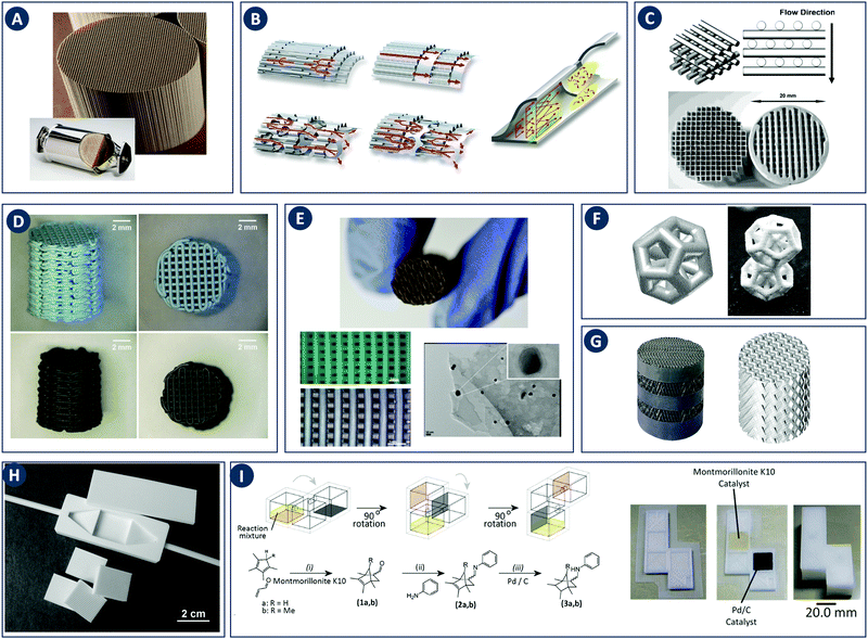 | ||
| Fig. 9 The use of 3D printing in structured catalyst fabrication. (A) Conventional extruded ceramic monolith as used in car catalytic converters. Inset: Monolith enclosed in metal casing. Reproduced from ref. 79 and 80 with permission from car engineer, copyright 2012. (B) Left: Structured metal foils as used by Emitec to create monoliths with enhanced mass transfer properties. Right: Detail of how turbulence is created by a wall segment that projects into the channel. Reproduced from ref. 66 with permission from Continental Emitec GmbH, copyright 2017. (C) Top: Schematic of the face-centered-cubic lattice structure, isometric and side views. Bottom: Comparison between conventional extruded (left) and robocast (right) monoliths with similar outer dimensions. Reproduced from ref. 5 with permission from American Chemical Society, copyright 2004. (D) Photographs of robocast alumina supports with embedded Cu-based catalysts, after low-temperature drying (top) and high-temperature sintering (bottom). Reproduced from ref. 72 with permission from Elsevier Inc., copyright 2015. (E) NiMo/PVA catalytic monolith after the pyrolysis of organic constitutes (top). Square patterned channels of 3D printed NiMo catalysts before and after pyrolysis (bottom left). NiMo/PVA/KOH catalysts (bottom right). Reproduced from ref. 73 with permission from WILEY-VCH Verlag GmbH & Co. KGaA, Weinheim, copyright 2017. (F) Comparison between a ceramic complex geometry (right) and the computer model used by Johnson Matthey to print shaped catalysts. Reproduced from ref. 74 and 75 with permission from Johnson Matthey Public Limited Company, copyright 2014. (G) Comparison between metal column packings as used in distillation (left) and the computer model used by BASF to print a structured monolith with a similar cross-flow structure. Reproduced from ref. 76,81 with permission from BASF Se, copyright 2010. (H) Alumina flow reactor fabricated using ceramic injection molding. The master molds were printed using stereolithography. Several inserts with immobilized catalysts are shown next to the reactor. Reproduced from ref. 77 with permission from Royal Society of Chemistry, copyright 2004. (I) Left: Schematic diagram of the reaction sequence in a three-stage batch reactor. The reaction mixture is depicted in yellow. The montmorillonite K10 and Pd on carbon catalysts immobilized in acetoxysilicone are shown in red and black, respectively. Right: Steps in the fabrication of the multistage reactor. From left to right: 3D printing of the polypropylene base plate via fused deposition modeling; catalyst deposition via robocasting; fused deposition modeling of reactor chamber walls and ceiling. Reproduced from ref. 78 with permission from Royal Society of Chemistry, copyright 2013. | ||
Processes that are penalized by a large pressure drop are usually performed in monoliths. For instance, an increase in the pressure drop over a car exhaust catalyst would increase fuel consumption by several percent.63 However, due to the small size of the channels in monoliths, the flow develops a laminar profile with relatively poor transfer conditions only a few millimeters behind the gas inlet. Mass transfer of reactants, i.e. transport from the gas or liquid phase to the catalytically active channel wall, is therefore dominated by diffusion.65 In car catalytic convertors at operating temperature, approximately 90% of the emissions is converted after passing through the first 10% of the monolith length. Because of the slow diffusion of the remaining low concentration of pollutants, the rest of the precious metal catalysts in the convertor is underutilized. In addition, removing the last pollutant traces is becoming more and more important considering ever more stringent emission norms. To address this issue, various options have been explored. Most commonly the length of the monolith is increased, resulting in it occupying more space and requiring more of the (expensive) catalytically active washcoat. Increasing the monolith cell density would reduce the channel size and reactant diffusion path, but would simultaneously lead to a disproportionate rise in pressure drop. Alternative approaches to enhance mass transfer are based on introducing turbulence to disrupt the laminar flow regime and/or promoting transverse mixing between the channels by cross-connections. The company Emitec manufactures several types of metal monoliths that improve mass transfer based on these principles to achieve higher pollutant conversion in automotive catalysis (Fig. 9B).66 Nevertheless, most catalyst supports are ceramics that cannot be obtained in these optimized shapes using traditional methods such as extrusion.
5.1 Fabrication and testing
Most attention in shaping three-dimensional catalyst bodies using additive fabrication tools has been devoted to structured monoliths with improved mass and heat transfer characteristics. Stuecker and coworkers used robocasting to create structured monoliths with a three-dimensional lattice of rods (725–1000 μm in diameter) stacked in such a way to avoid straight end-to-end pathways through the monolith (Fig. 9C).5 In the design stage, CFD calculations were used to determine a rod size and spacing combination that provided the most turbulence to promote internal mass transfer without dramatically increasing the pressure drop. The resulting monoliths had a face-centered-cubic structure with high surface-to-volume ratio (15–43 cm2 cm−3). The build material that was used, a ceramic hexa-aluminate, is intrinsically active in the catalytic combustion of methane. Under otherwise identical conditions, robocast lattices converted approximately six times more methane at 600 °C than extruded monoliths. The same team reported later a further improvement of the face-centered-cubic geometry.67Van Noyen and coworkers used robocasting to fabricate Ti-alloy and stainless steel monoliths that were subsequently coated with zeolite crystals as catalysts in the decomposition of N2O and the conversion of methanol to olefins.68–70 Especially in the second case, structured catalysts add value by enabling well-controlled contact times and fast evacuation of the desired reaction products, as further conversion of olefins yields side-products that eventually deactivate the catalyst through coking. Denayer and coworkers demonstrated robocast monoliths consisting of ZSM-5 zeolite and a binder consisting of silica and bentonite. After calcination, the printed structures were successfully tested in breakthrough separation experiments of CO2/N2 and CO2/CH4 mixtures thanks to the 65% zeolite loading.71 Tubio et al. demonstrated that direct incorporation of a catalyst precursor during robocasting of the ceramic support is possible.72 They prepared an aqueous colloidal gel ink based on a mixture of Al2O3 ceramic powder, polymer binders, and Cu(NO3)2. After sintering the robocast monoliths at 1400 °C, robust ceramic supports loaded with 2–3 wt% of the mixed CuO/CuAl2O4 catalyst were obtained (Fig. 9D). The functionalized supports were used in Ullmann-type coupling reactions for C–N bond formation, resulting in N-aryl yields of 78–94%. No copper leaching was observed and the catalytic monoliths could be recycled at least 10 times, with only a 5% decrease in yield. Beltramini and coworkers demonstrated recently that carbon monoliths carrying catalytically active NiMoO2 nanoparticles can be fabricated by robocasting a paste containing polyvinyl alcohol, starch and metal salts and subsequently subjecting the printed structure to pyrolysis at 700 °C. Even though the as-printed monolith loses 70% of its initial weight during pyrolysis, its geometry is maintained due to uniform shrinkage. The final catalyst-loaded carbon monolith contains up to 25 wt% active species and was successfully tested in the syngas-to-alcohol conversion at high feed flow rates (Fig. 9E).73
Powder bed 3D printing methods have been explored as well to produce shaped catalysts, especially by industrial catalyst manufacturers. Johnson Matthey described the use of 3D printing processes to obtain geometrically complex ceramic supports for use in packed beds (Fig. 9F).74,75 These 3D printed bodies had a higher geometric surface area compared to what could be achieved using conventional pelletizing, extruding or granulating approaches. BASF patented the use of 3D printing via binder jetting to produce structured monoliths that allow high transverse mixing while maintaining a small pressure drop.76 To enhance mass transport in the printed monoliths, a cross-channel geometry is adopted similar to structured packings used in distillation columns and produced by manufacturers such as Montz or Sulzer. To this end, the channels in the printed monoliths through which the reaction medium flows are inclined 30–60° to the main flow direction (Fig. 9G). The monolith can be printed either using a catalytically active build powder or an inert support material that is subsequently functionalized, similar to the robocasting approaches described in ref. 5 and 70, respectively. To illustrate the advantage of a cross-channel structure printed in SiO2 compared to a packed bed of extrudates of the same material (diameter 1.5 mm; length 5–10 mm), the pressure drop over both was measured at different gas flow velocities. Whereas the pressure difference over the monolith was 4.7 and 280 mbar m−1 for flow velocities of 1 and 10 m s−1, the values for the packed bed were considerably higher, at 300 and 2000 mbar m−1, respectively.
In addition to structured monoliths, 3D printing enables to fabricate geometrically complex reaction vessels and microreactors with integrated catalysts.38 Already over a decade ago, Knitter and Liauw demonstrated the fabrication of a modular alumina microreactor using a 3D printing process chain (Fig. 9H).77 Stereolithography was used to produce master molds, taking into account the expected shrinkage during sintering (approx. 12%). These models are copied into silicone rubber molds for use in injection molding with a combination of ceramic powders and low-melting wax binders. After binder burn-out, sintering and applying the catalyst to the alumina reactor walls, two heterogeneously catalyzed gas phase reactions were successfully tested at temperatures of up to 1000 °C: the oxidative coupling of methane and the selective oxidation of isoprene, catalyzed by lithium aluminate and titania-supported vanadia, respectively. Cronin and coworkers demonstrated an acetoxysilicone ink containing Pd supported on carbon. When used in robocasting elastomer batch reactors, the sections printed using this functionalized ink were able to efficiently catalyze the transfer hydrogenation of styrene to ethylbenzene.30 The same team also realized an integrated multistage batch reactor to perform a three-step organic reaction sequence consisting of (i) a Diels–Alder cyclization, (ii) the formation of an imine and (iii) hydrogenation of the imine to the corresponding secondary amine.78 These successive reaction steps where initiated by 90° rotations of an appropriately designed polypropylene reactor, to let gravity transfer the reactants through the various reaction chambers with different catalysts immobilized in acetoxysilicone ink (Fig. 9I). In the same study it was shown how non-printable functional components (e.g. stirring bars or a silica separation column) can be added to the reactor during pre-programed pauses in the printing schedule or via well-designed slots in the reactor wall.
5.2 Modeling and characterization
When computationally studying catalytic process in monoliths, it is sufficient to model a single channel as a representation of the entire structure due to their regular nature. Canu and Vecchi used CFD to study the catalytic combustion of a methane/air mixture in a square cross-section monolith.82 Their results showed that while CFD can capture the fluid flow and heat transfer, more detailed surface and gas-phase reaction mechanisms must be considered. The DETCHEM computer package is an example of a multiscale modeling toolbox that can be used to achieve this goal through the description of surface and gas phase reactions by elementary-step reaction mechanisms (Fig. 10A). This microkinetic modeling tool can be linked to the fluid dynamics of a reactor by e.g. using boundary layer approaches as shown for the partial oxidation of methane by Schwiedernoch et al. and the partial oxidation of iso-octane by Hartmann et al.83,84 This approach can be also coupled to a full CFD solution to study non-steady-state cases, as demonstrated by Quiceno et al.85 Full CFD coupling to a microkinetic model also allows to explore geometric parameters, Maffei et al. analyzed circular (diameter 1 mm) and square ducts (edge length 1 mm) as reactor configurations for the adiabatic partial oxidation of methane.86 They found that the outlet composition and temperature do not differ between channel configurations, but that they vary locally inside the reactors due to different local transport properties (Fig. 10B).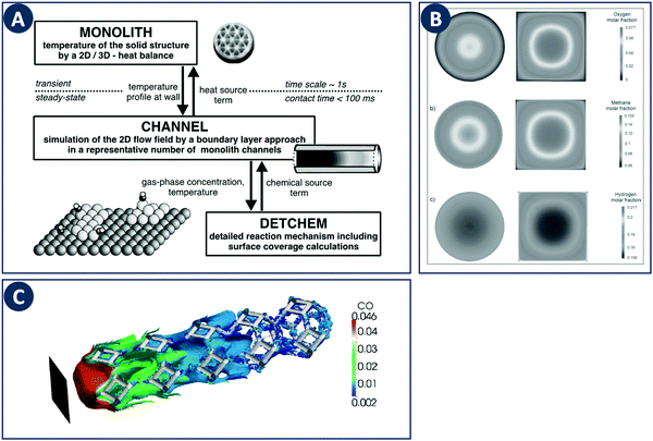 | ||
| Fig. 10 Examples of multiscale modeling of structured catalysts. (A) Representation of the coupling of different models across multiple time- and length-scales. Reproduced from ref. 83 with permission from Elsevier Science Ltd, copyright 2003. (B) Computational study of the effect of the channel cross-sections in monolithic reactors. The individual panels show contours of the (a) methane, (b) oxygen, and (c) hydrogen molar fraction. Reproduced from ref. 86 with permission from WILEY-VCH Verlag GmbH & Co. KGaA, Weinheim, copyright 2014. (C) Multiscale modeling of a foam-like structured catalyst. The image shows the isosurface of CO for an inlet CO mass fraction 4.6%, feed flow rate of 3000 Ncc min−1 and at a temperature of 620 K. Reproduced from ref. 88 with permission from Elsevier Ltd, copyright 2016. | ||
These multiscale modeling approaches have also been applied to the afore discussed foam-like structures. To study realistic foam structures, Wehinger et al. proposed a fully automatic workflow in which a foam structure is generated based on a random distribution of points with the porosity, specific surface area and ligament dimensions as input parameters.87 This algorithm was used to model the partial oxidation of methane inside a catalytic foam structure taking into account heat transfer in the solid, and the obtained species profiles match well with experiments. The modeling of catalytic foams was also reported by Della Torre et al. based on a coupled finite-volume/finite-area strategy which captures the fluid phase hydrodynamics and the chemical processes occurring on the solid phase (Fig. 10C).88 For the latter part, adsorption and desorption on the active sites and the surface reaction is modeled on the basis of a Langmuir–Hinshelwood mechanism. Coupling a detailed kinetic model with a CFD solver to resolve the complex flow inside porous structures allows computational optimization studies of local temperatures, species concentrations, and mixing in the bulk fluid. Coupled with additive manufacturing, novel and improved porous designs can be fabricated and validated experimentally.
6 Perspectives
The impact of digital fabrication on the field of catalytic technology and chemical engineering is steadily increasing. The rapid and seamless transition between digital data and physical objects, inherent to a digital fabrication flow, will be of increasing value in streamlining both research and manufacture of reactors and structured catalysts. The increasing availability of 3D printing hardware is rapidly lowering the equipment threshold and thereby enabling creative contributions from researchers with a core expertise in fields such as catalytic technology and chemical engineering. Most work in this area focused on improving mass transfer through geometry optimization, thereby often demonstrating the value of CFD approaches. Nevertheless, the first illustrations of catalysts and reactors with additional printed-in chemical functionality hint at even richer opportunities when chemistry and engineering are considered as one in the design stage. Given the rapid progress in 3D printing functional components such as high-performance heaters (Fig. 11A), it will be very interesting to see what opportunities arise from combining digital control over geometry, function and chemical composition in structured catalysts and reactors. Different strategies to incorporate both printable and non-printable functional components widen the context in which digitally fabricated reactors can make an impact. For instance, electrochemical reactions have been performed by using electrodes directly printed as part of the reactor design as well as by using exchangeable electrodes attached via a printed threaded port (Fig. 11B).30,89 Similarly, the integration of both batch and flow reactors with spectroscopic reaction monitoring via FTIR and UV-Vis was demonstrated (Fig. 11C).30,39,90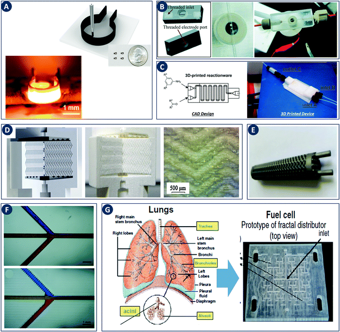 | ||
| Fig. 11 Recent developments in digital fabrication. (A) Robocasting high-temperature high-rate heaters based on reduced graphene oxide. Top: Illustration of the robocasting procedure, inset: photograph of heaters with a 1.5 mm diameter. Bottom: Robocast heater under high-temperature operation (1800 K). Reproduced from ref. 100 with permission from American Chemical Society, copyright 2016. (B) 3D device used for electrochemical detection. Left: CAD design. Right: 3D printed 0.5 mm-wide channel device in VeroClear material. The Pt-electrode is screwed into the electrode port. Reproduced from ref. 89 with permission from Royal Society of Chemistry, copyright 2014. (C) PP version of a flow reactor, with a channel diameter of 1.5 mm. Reproduced from ref. 90 with permission from Beilstein Journal of Organic Chemistry, copyright 2013. (D) 3D printed chromatographic columns. Left: Computer model. Middle and right: Cutaway of the printed columns and a zoom of the internal herringbone motif. Reproduced from ref. 94 with permission from Elsevier B.V., copyright 2014. (E) A stainless steel 3D-printed sheet gyroid heat exchanger. Reproduced from ref. 95 with permission from Elsevier Ltd, copyright 2017. (F) Comparison of 3D printed microchannels built flat and on-edge. Reproduced from ref. 33 with permission from Royal Society of Chemistry, copyright 2014. (G) Fuel cell design guided by the architecture of the lung. Reproduced from ref. 98 with permission from the Centre National de la Recherche Scientifique (CNRS) and the Royal Society of Chemistry, copyright 2016. | ||
3D printed structured catalysts are excellent research tools, but might also find application in commercial production of small to medium catalyst batches with custom geometries or sizes. Similarly, robocast ceramic lattice filters have found application as customizable filtration media for melted metal in foundries.91,92 Further opportunities are likely to be found in application areas closely related to structured catalysts, such as structured column internals for reactive distillations, 3D printed chromatographic media (Fig. 11D) and optimized heat exchanger internals (Fig. 11E).93,94 For instance, 3D printed metal sheet gyroids offer intriguing possibilities for heat exchangers as this geometry creates two uniformly dispersed but independent flow channels with high interfacial surface area. Preliminary data by Fee and coworkers indicate that heat transfer rates in a stainless steel sheet gyroid heat exchanger are far higher than in flat-plate or shell-and-tube models of comparable size. Further opportunities are likely to be found in functionally graded materials, for instance by defining a specific porosity of the bed near inlets or outlets.95 For mass produced structured catalysts such as car catalytic converters, it remains to be seen if the intense research effort in speeding up 3D printing processes will make larger-scale manufacturing (as opposed to prototyping) economically feasible.96
3D printed reactors will likely first satisfy the fast-changing needs in the research lab, where they can be designed and potentially manufactured to perform highly specific experiments, if desired through interfacing with peripheral analysis equipment. In addition, if additive fabrication facilitates the use of concepts such as flow reactors at the lab scale, the industrial production level might be directly influenced. For instance in the pharmaceutical and other fine chemical industries, the use of batch reactors in production is directly related to the protocols used in lab scale synthesis of products. The introduction of flow chemistry at the lab scale would enable the exploration and scale-up of a broader range synthesis conditions (e.g. not deemed safe in batch reactors) and therefore enable protocols and products currently not accessible at the production scale. Broader impact of additive manufacturing in continuous flow production would be facilitated as well by increasing the thermal and chemical compatibility of 3D printing build materials.32 Major steps have already been taken by demonstrating 3D printing in polypropylene, metals and ceramics. Nevertheless, improvements are still needed, for instance in decreasing printing costs, controlling the surface roughness of reactor internals, standards and standardized test protocols, etc. New fabrication approaches could help in addressing those challenges. For instance, the internal surface roughness in 3D printed reactors is directly related to part orientation during printing, the layer thickness and the method of generating internal voids (e.g. type and removal of support material) (Fig. 11F). In the neighboring field of microfluidics, stereolithography is gaining momentum to fabricate chips with internal flow channels and high surface quality.33 Unfortunately, photoresins generally have poor thermal and chemical stability. ‘Ceramic stereolithography’ to produce high-quality ceramic parts by photo-crosslinking ceramic powders followed by binder burn-out and sintering could be an interesting route to explore in this context.9 Compared to ceramic injection molding, this approach enables more complex geometries and avoids the costs and delays of mold fabrication.
In digital fabrication, user involvement with the entire design and manufacturing flow allows precise control and rapid optimization with a level of flexibility that is not currently available. This different modus operandi will have to go hand in hand with new research approaches. For instance, the complex geometries unlocked by digital manufacturing align well with the research efforts in nature-inspired engineering.97 As highlighted by the work of Coppens et al., structures from nature can be a source of inspiration for technical solutions. For instance, hierarchical distribution networks with equal hydraulic path lengths, as encountered in the upper respiratory tract and tree crowns, minimize transport limitations in a scalable way. The use of such structures, realized through SLA and other methods, has been demonstrated in a range of applications, ranging from improved fuel cell designs to secondary gas injectors for fluidized beds (Fig. 11G).98 Additionally, the introduction of digital manufacturing will require rethinking how of other aspects of research and training. For instance, digital fabrication will shift significant intellectual property towards easy-to-share computer files. While in the academic community such openness is mostly embraced,99 industrial researchers might hesitate to outsource 3D printing of proprietary components. As rightly stated by Grande and colleagues, and as illustrated by some of the examples above, an optimized digital fabrication workflow will almost certainly involve modeling.38 The opportunities in accurately fabricating computer-optimized geometries and experimentally studying their properties will lead to an intensified interaction between the experimental and modeling communities and the need for interdisciplinary profiles. These and other changes might become part of educational programs to train scientists and engineers that make optimal use of the exciting new possibilities enabled by digital fabrication.
Conflicts of interest
There are no conflicts to declare.Acknowledgements
C. P. acknowledges the Research Foundation – Flanders (FWO) for a postdoctoral fellowship. S. K. acknowledges funding from the European Commission (via FP7 Marie Curie CIG 2013 Action No. 614975) and FWO (Odysseus II Grant No. G0E6314N). R. A. acknowledges KU Leuven (projects STG/14/07BF and C24/16/022), FWO (1516717N) and the European Commission (H2020-RIA project, HCCAT 720996) for funding.References
- I. Gibson, D. W. Rosen and B. Stucker, Additive manufacturing technologies: rapid prototyping to direct digital manufacturing, Springer, London, New York, 2010 Search PubMed.
- ‘Additive manufacturing’ would be a more accurate designation for the entire family of technologies capable of generating 3D objects directly from digital data. Given the increasing and widespread use of the term ‘3D printing’, both terms will be used interchangeably.
- T. Van Gerven and A. Stankiewicz, Ind. Eng. Chem. Res., 2009, 48, 2465–2474 CrossRef CAS.
- J. Cesarano and P. D. Calvert, US6027326 A, 2000.
- J. N. Stuecker, J. E. Miller, R. E. Ferrizz, J. E. Mudd and J. Cesarano, Ind. Eng. Chem. Res., 2004, 43, 51–55 CrossRef CAS.
- J. A. Lewis, J. E. Smay, J. Stuecker and J. Cesarano, J. Am. Ceram. Soc., 2006, 89, 3599–3609 CrossRef CAS.
- J. Klein, M. Stern, G. Franchin, M. Kayser, C. Inamura, S. Dave, J. C. Weaver, P. Houk, P. Colombo, M. Yang and N. Oxman, 3D Print. Addit. Manuf., 2015, 2, 92–105 CrossRef.
- J.-W. Choi, H.-C. Kim and R. Wicker, J. Mater. Process. Technol., 2011, 211, 318–328 CrossRef CAS.
- J. W. Halloran, Annu. Rev. Mater. Res., 2016, 46, 19–40 CrossRef CAS.
- F. Kotz, K. Arnold, W. Bauer, D. Schild, N. Keller, K. Sachsenheimer, T. M. Nargang, C. Richter, D. Helmer and B. E. Rapp, Nature, 2017, 544, 337–339 CrossRef CAS PubMed.
- Fuel cell electronics packaging, ed. K. Kuang and K. Easler, Springer, New York, 2007 Search PubMed.
- J. G. Jardine, T. Ota, D. Sok, M. Pauthner, D. W. Kulp, O. Kalyuzhniy, P. D. Skog, T. C. Thinnes, D. Bhullar, B. Briney, S. Menis, M. Jones, M. Kubitz, S. Spencer, Y. Adachi, D. R. Burton, W. R. Schief and D. Nemazee, Science, 2015, 349, 156–161 CrossRef CAS PubMed.
- A. Zocca, C. M. Gomes, A. Staude, E. Bernardo, J. Günster and P. Colombo, J. Mater. Res., 2013, 28, 2243–2252 CrossRef CAS.
- S. H. Ko, J. Chung, N. Hotz, K. H. Nam and C. P. Grigoropoulos, J. Micromech. Microeng., 2010, 20, 125010 CrossRef.
- A. Kamyshny, J. Steinke and S. Magdassi, Open Appl. Phys. J., 2011, 4, 19–36 CrossRef CAS.
- F. Castles, D. Isakov, A. Lui, Q. Lei, C. E. J. Dancer, Y. Wang, J. M. Janurudin, S. C. Speller, C. R. M. Grovenor and P. S. Grant, Sci. Rep., 2016, 6, 22714 CrossRef CAS PubMed.
- C. W. Foster, M. P. Down, Y. Zhang, X. Ji, S. J. Rowley-Neale, G. C. Smith, P. J. Kelly and C. E. Banks, Sci. Rep., 2017, 7, 42233 CrossRef PubMed.
- J. A. M. Kuipers and W. P. M. van Swaaij, in Advances in Chemical Engineering, Elsevier, 1998, vol. 24, pp. 227–328 Search PubMed.
- M. J. Nieves-Remacha, A. A. Kulkarni and K. F. Jensen, Ind. Eng. Chem. Res., 2015, 54, 7543–7553 CrossRef CAS.
- K.-J. Wu, V. Nappo and S. Kuhn, Ind. Eng. Chem. Res., 2015, 54, 7554–7564 CrossRef CAS.
- Making use of the Einstein summation convention.
- M. Salciccioli, M. Stamatakis, S. Caratzoulas and D. G. Vlachos, Chem. Eng. Sci., 2011, 66, 4319–4355 CrossRef CAS.
- J.-C. Charpentier, Chem. Eng. Res. Des., 2010, 88, 248–254 CrossRef CAS.
- K. S. Elvira, X. C. i Solvas, R. C. R. Wootton and A. J. deMello, Nat. Chem., 2013, 5, 905–915 CrossRef CAS PubMed.
- B. Gutmann, D. Cantillo and C. O. Kappe, Angew. Chem., Int. Ed., 2015, 54, 6688–6728 CrossRef CAS PubMed.
- A. Adamo, R. L. Beingessner, M. Behnam, J. Chen, T. F. Jamison, K. F. Jensen, J.-C. M. Monbaliu, A. S. Myerson, E. M. Revalor, D. R. Snead, T. Stelzer, N. Weeranoppanant, S. Y. Wong and P. Zhang, Science, 2016, 352, 61 CrossRef CAS PubMed.
- G. Caygill, M. Zanfir and A. Gavriilidis, Org. Process Res. Dev., 2006, 10, 539–552 CrossRef CAS.
- K. F. Jensen, B. J. Reizman and S. G. Newman, Lab Chip, 2014, 14, 3206–3212 RSC.
- K. F. Jensen, AIChE J., 2017, 63, 858–869 CrossRef CAS.
- M. D. Symes, P. J. Kitson, J. Yan, C. J. Richmond, G. J. T. Cooper, R. W. Bowman, T. Vilbrandt and L. Cronin, Nat. Chem., 2012, 4, 349–354 CrossRef CAS PubMed.
- P. J. Kitson, R. J. Marshall, D. Long, R. S. Forgan and L. Cronin, Angew. Chem., Int. Ed., 2014, 53, 12723–12728 CrossRef CAS PubMed.
- A. J. Capel, S. Edmondson, S. D. R. Christie, R. D. Goodridge, R. J. Bibb and M. Thurstans, Lab Chip, 2013, 13, 4583 RSC.
- A. K. Au, W. Lee and A. Folch, Lab Chip, 2014, 14, 1294–1301 RSC.
- A. Urrios, C. Parra-Cabrera, N. Bhattacharjee, A. M. Gonzalez-Suarez, L. G. Rigat-Brugarolas, U. Nallapatti, J. Samitier, C. A. DeForest, F. Posas, J. L. Garcia-Cordero and A. Folch, Lab Chip, 2016, 16, 2287–2294 RSC.
- J. Zhang, K. Wang, A. R. Teixeira, K. F. Jensen and G. Luo, Annu. Rev. Chem. Biomol. Eng., 2017, 8, 285–305 CrossRef PubMed.
- J. C. B. Lopes, P. E. M. Dos Santos Da Costa Laranjeira, M. M. G. Q. Dias and A. A. A. Martins, US8434933 B2, 2013.
- C. M. Fonte, M. E. Leblebici, M. M. Dias and J. C. B. Lopes, Chem. Eng. Res. Des., 2013, 91, 2250–2258 CrossRef CAS.
- C. A. Grande, J.-L. Dubois, J. C. P. Camblor, Ø. Vistad, T. Didriksen, R. Blom, A. I. Spjelkavik and D. Akporiaye, Additive manufacturing: haute couture for chemical industries, DOI:10.13140/RG.2.1.1356.5520.
- P. J. Kitson, M. H. Rosnes, V. Sans, V. Dragone and L. Cronin, Lab Chip, 2012, 12, 3267 RSC.
- S. Rossi, R. Porta, D. Brenna, A. Puglisi and M. Benaglia, Angew. Chem., 2017, 129, 4354–4358 CrossRef.
- C. Hutter, A. Zenklusen, R. Lang and P. Rudolf von Rohr, Chem. Eng. Sci., 2011, 66, 1132–1141 CrossRef CAS.
- J.-N. Tourvieille, R. Philippe and C. de Bellefon, Chem. Eng. Sci., 2015, 126, 406–426 CrossRef CAS.
- A. Potdar, L. N. Protasova, L. Thomassen and S. Kuhn, React. Chem. Eng., 2017, 2, 137–148 CAS.
- R. D. Sochol, E. Sweet, C. C. Glick, S. Venkatesh, A. Avetisyan, K. F. Ekman, A. Raulinaitis, A. Tsai, A. Wienkers, K. Korner, K. Hanson, A. Long, B. J. Hightower, G. Slatton, D. C. Burnett, T. L. Massey, K. Iwai, L. P. Lee, K. S. J. Pister and L. Lin, Lab Chip, 2016, 16, 668–678 RSC.
- H. Gong, A. T. Woolley and G. P. Nordin, Lab Chip, 2016, 16, 2450–2458 RSC.
- D. Seguin, A. Montillet and J. Comiti, Chem. Eng. Sci., 1998, 53, 3751–3761 CrossRef CAS.
- D. Seguin, A. Montillet, J. Comiti and F. Huet, Chem. Eng. Sci., 1998, 53, 3897–3909 CrossRef CAS.
- J. Comiti, N. E. Sabiri and A. Montillet, Chem. Eng. Sci., 2000, 55, 3057–3061 CrossRef CAS.
- To be distinguished from the commonly encountered empty tube Reynolds number.
- N. A. Horton and D. Pokrajac, Phys. Fluids, 2009, 21, 045104 CrossRef.
- M. H. J. Pedras and M. J. S. de Lemos, Int. J. Heat Mass Transfer, 2001, 44, 1081–1093 CrossRef.
- K. Boomsma, D. Poulikakos and Y. Ventikos, Int. J. Heat Fluid Flow, 2003, 24, 825–834 CrossRef.
- S. Krishnan, J. Y. Murthy and S. V. Garimella, J. Heat Transfer, 2006, 128, 793 CrossRef.
- S. Krishnan, S. V. Garimella and J. Y. Murthy, J. Heat Transfer, 2008, 130, 024503 CrossRef.
- S. R. Annapragada, J. Y. Murthy and S. V. Garimella, Numer. Heat Transfer, Part B, 2008, 54, 1–22 CrossRef CAS.
- D. A. G. von der Schulenburg, M. Paterson-Beedle, L. E. Macaskie, L. F. Gladden and M. L. Johns, J. Mater. Sci., 2007, 42, 6541–6548 CrossRef.
- P. Habisreuther, N. Djordjevic and N. Zarzalis, Chem. Ing. Tech., 2008, 80, 327–341 CrossRef CAS.
- C. Hutter, A. Zenklusen, S. Kuhn and P. Rudolf von Rohr, Chem. Eng. Sci., 2011, 66, 519–529 CrossRef CAS.
- A. Della Torre, G. Montenegro, G. R. Tabor and M. L. Wears, Int. J. Heat Fluid Flow, 2014, 50, 72–82 CrossRef.
- X. Fan, X. Ou, F. Xing, G. A. Turley, P. Denissenko, M. A. Williams, N. Batail, C. Pham and A. A. Lapkin, Catal. Today, 2016, 278, 350–360 CrossRef CAS.
- F. Lucci, A. Della Torre, G. Montenegro, R. Kaufmann and P. Dimopoulos Eggenschwiler, Int. J. Heat Mass Transfer, 2017, 108, 341–350 CrossRef CAS.
- Handbook of Heterogeneous Catalysis: Online, ed. G. Ertl, H. Knozinger, F. Schuth and J. Weitkamp, Wiley-VCH Verlag GmbH & Co. KGaA, Weinheim, Germany, 2008 Search PubMed.
- Structured catalysts and reactors, ed. A. Cybulski and J. A. Moulijn, Taylor & Francis, Boca Raton, 2nd edn, 2006 Search PubMed.
- D. Schlereth and O. Hinrichsen, Ind. Eng. Chem. Res., 2014, 53, 11550–11556 CrossRef CAS.
- R. E. Hayes and S. T. Kolaczkowski, Chem. Eng. Sci., 1994, 49, 3587–3599 CrossRef.
- Continental Emitec GmbH, http://www.emitec.com/en/technology/catalyst-substrates/structured-foils/, (accessed August 24, 2017).
- R. M. Ferrizz, J. N. Stuecker, J. Cesarano and J. E. Miller, Ind. Eng. Chem. Res., 2005, 44, 302–308 CrossRef CAS.
- J. Lefevere, S. Mullens, V. Meynen and J. V. Noyen, Chem. Pap., 2014, 68, 1143–1153 CAS.
- J. Lefevere, M. Gysen, S. Mullens, V. Meynen and J. Van Noyen, Catal. Today, 2013, 216, 18–23 CrossRef CAS.
- J. Van Noyen, A. Wilde, M. Schroeven, S. Mullens and J. Luyten, Int. J. Appl. Ceram. Technol., 2012, 9, 902–910 CrossRef CAS.
- S. Couck, J. Lefevere, S. Mullens, L. Protasova, V. Meynen, G. Desmet, G. V. Baron and J. F. M. Denayer, Chem. Eng. J., 2017, 308, 719–726 CrossRef CAS.
- C. R. Tubío, J. Azuaje, L. Escalante, A. Coelho, F. Guitián, E. Sotelo and A. Gil, J. Catal., 2016, 334, 110–115 CrossRef.
- M. Konarova, W. Aslam, L. Ge, Q. Ma, F. Tang, V. Rudolph and J. N. Beltramini, ChemCatChem DOI:10.1002/cctc.201700829.
- D. R. Coupland, US20130230721 A1, 2013.
- D. R. Coupland, EP2752244 A1, 2014.
- N. Kashani-Shirazi, V. Wloka, W. Gerlinger, A. Schmidt, K. Heinen and W. Kollenberg, US20100222209 A1, 2010.
- R. Knitter and M. A. Liauw, Lab Chip, 2004, 4, 378 RSC.
- P. J. Kitson, M. D. Symes, V. Dragone and L. Cronin, Chem. Sci., 2013, 4, 3099–3103 RSC.
- R. Nicolas, Cordierite for catalytic converters, http://www.car-engineer.com/cordierite-for-catalytic-converters/, (accessed August 24, 2017).
- The Catalytic Converter Quiz, http://quizzes.howstuffworks.com/quiz/catalytic-converter-quiz, (accessed August 24, 2017).
- Gauze Packings – Sulzer, http://https://www.sulzer.com/en/Products-and-Services/Separation-Technology/Structured-Packings/Gauze-Packings-BX-CY-BXPlus-AYPlus-DC-Hyperfil-and-Multifil, (accessed August 24, 2017).
- P. Canu and S. Vecchi, AIChE J., 2002, 48, 2921–2935 CrossRef CAS.
- R. Schwiedernoch, S. Tischer, C. Correa and O. Deutschmann, Chem. Eng. Sci., 2003, 58, 633–642 CrossRef CAS.
- M. Hartmann, L. Maier, H. D. Minh and O. Deutschmann, Combust. Flame, 2010, 157, 1771–1782 CrossRef CAS.
- R. Quiceno, O. Deutschmann, J. Warnatz and J. Pérez-Ramírez, Catal. Today, 2007, 119, 311–316 CrossRef CAS.
- T. Maffei, S. Rebughini, G. Gentile, S. Lipp, A. Cuoci and M. Maestri, Chem. Ing. Tech., 2014, 86, 1099–1106 CrossRef CAS.
- G. D. Wehinger, H. Heitmann and M. Kraume, Chem. Eng. J., 2016, 284, 543–556 CrossRef CAS.
- A. Della Torre, F. Lucci, G. Montenegro, A. Onorati, P. Dimopoulos Eggenschwiler, E. Tronconi and G. Groppi, Comput. Chem. Eng., 2016, 92, 55–63 CrossRef CAS.
- J. L. Erkal, A. Selimovic, B. C. Gross, S. Y. Lockwood, E. L. Walton, S. McNamara, R. S. Martin and D. M. Spence, Lab Chip, 2014, 14, 2023–2032 RSC.
- V. Dragone, V. Sans, M. H. Rosnes, P. J. Kitson and L. Cronin, Beilstein J. Org. Chem., 2013, 9, 951–959 CrossRef CAS PubMed.
- J. N. Stuecker, J. Cesarano and J. E. Miller, US7527671B1, 2006.
- Lattice Filtration, http://https://www.robocasting.net/index.php/products/filtration, (accessed August 24, 2017).
- S. Sandron, B. Heery, V. Gupta, D. A. Collins, E. P. Nesterenko, P. N. Nesterenko, M. Talebi, S. Beirne, F. Thompson, G. G. Wallace, D. Brabazon, F. Regan and B. Paull, Analyst, 2014, 139, 6343–6347 RSC.
- C. Fee, S. Nawada and S. Dimartino, J. Chromatogr. A, 2014, 1333, 18–24 CrossRef CAS PubMed.
- C. Fee, Curr. Opin. Chem. Eng., 2017, 18, 10–15 CrossRef.
- J. R. Tumbleston, D. Shirvanyants, N. Ermoshkin, R. Janusziewicz, A. R. Johnson, D. Kelly, K. Chen, R. Pinschmidt, J. P. Rolland, A. Ermoshkin, E. T. Samulski and J. M. DeSimone, Science, 2015, aaa2397 Search PubMed.
- M.-O. Coppens, Curr. Opin. Chem. Eng., 2012, 1, 281–289 CrossRef CAS.
- P. Trogadas, M. M. Nigra and M.-O. Coppens, New J. Chem., 2016, 40, 4016–4026 RSC.
- P. J. Kitson, S. Glatzel, W. Chen, C.-G. Lin, Y.-F. Song and L. Cronin, Nat. Protoc., 2016, 11, 920–936 CrossRef CAS PubMed.
- Y. Yao, K. K. Fu, C. Yan, J. Dai, Y. Chen, Y. Wang, B. Zhang, E. Hitz and L. Hu, ACS Nano, 2016, 10, 5272–5279 CrossRef CAS PubMed.
| This journal is © The Royal Society of Chemistry 2018 |


