
 Open Access Article
 This Open Access Article is licensed under a
 Creative Commons Attribution 3.0 Unported Licence
Non-covalent interactions in anisole–(CO2)n (n = 1, 2) complexes
Maurizio
Becucci
 *ab,
Federico
Mazzoni
ab,
Giangaetano
Pietraperzia
ab,
Jan
Řezáč
c,
Dana
Natchigallová
c and
Pavel
Hobza
c
*ab,
Federico
Mazzoni
ab,
Giangaetano
Pietraperzia
ab,
Jan
Řezáč
c,
Dana
Natchigallová
c and
Pavel
Hobza
c
aDipartimento di Chimica ‘Ugo Schiff’, Università degli Studi di Firenze, via della Lastruccia 3, 50019 Sesto Fiorentino (FI), Italy. E-mail: maurizio.becucci@unifi.it
bEuropean Laboratory for Non-Linear Spectroscopy, via Nello Carrara 1, 50019, Sesto Fiorentino (FI), Italy
cInstitute of Organic Chemistry and Biochemistry, Academy of Sciences of the Czech Republic, Flemingovo nám. 2, 166 10 Prague 6, Czech Republic
First published on 7th August 2017
Abstract
Non-covalent interactions are ubiquitous and represent a very important binding motif. The direct experimental measurement of binding energies in complexes has been elusive for a long time despite its importance, for instance, for understanding and predicting the structure of bio-macromolecules. Here, we report a combined experimental and computational analysis on the 1![[thin space (1/6-em)]](https://www.rsc.org/images/entities/char_2009.gif) :1 and 1:2 clusters formed by anisole (methoxybenzene) and carbon dioxide molecules. We have obtained a detailed description of the interaction between CO2 and anisole. This system represents quite a challenging test for the presently available experimental and theoretical methods for the characterization of weakly bound molecular complexes. The results, evaluated in the framework of previous studies on anisole clusters, show a very good agreement between experimental and theoretical data. A comparison of the experimental and computational data enabled the binding energy values of the 1:1 and 1:2 clusters to be determined in the ground electronic state of the neutral and cation complex and in the first excited singlet state of the neutral complex. In addition, it was possible to adduce the presence of different 1:1+ conformers, prepared by direct ionization of the 1:1 complex or by dissociative ionization of the 1:2 complex.
:1 and 1:2 clusters formed by anisole (methoxybenzene) and carbon dioxide molecules. We have obtained a detailed description of the interaction between CO2 and anisole. This system represents quite a challenging test for the presently available experimental and theoretical methods for the characterization of weakly bound molecular complexes. The results, evaluated in the framework of previous studies on anisole clusters, show a very good agreement between experimental and theoretical data. A comparison of the experimental and computational data enabled the binding energy values of the 1:1 and 1:2 clusters to be determined in the ground electronic state of the neutral and cation complex and in the first excited singlet state of the neutral complex. In addition, it was possible to adduce the presence of different 1:1+ conformers, prepared by direct ionization of the 1:1 complex or by dissociative ionization of the 1:2 complex.
Introduction
Non-covalent interactions have always been a very debated subject in chemistry and physics, since their introduction in the work of van der Waals1 as an attempt to build suitable analytical functional forms for their description,2,3 up to their accurate characterization by both computational and experimental means.4 Many different interaction schemes have been devised in order to define guidelines for their effective introduction in simple molecular modeling processes. The approximations involved have been verified by high-level quantum calculations5 and accurate experimental data.6 Modern experiments on isolated gas phase systems provide details on the intermolecular interaction for well-defined systems: two or a few interacting moieties without any perturbation from the solvent or the lattice. The adiabatic expansion of gas mixtures (containing the relevant chemicals and a carrier gas, typically helium) in very low-pressure chambers allows the formation and stabilization of molecular clusters.Research activity has been focused mostly on very simple molecular systems, such as complexes formed by diatomic or triatomic molecules, or larger ones, usually containing an aromatic molecule. The aromatic molecule acts as the chromophore for electronic spectroscopy experiments as a consequence of its easily accessible S1–S0 electronic transition. Different kinds of experiments can be performed to determine its spectroscopic properties, its structure (e.g. from rotationally resolved data), or its binding energy (usually by means of photoionization/mass spectrometry experiments).6–8 This kind of data can easily and directly be compared with the results of model calculations. Many examples of clusters where the two moieties interact through hydrogen-bond, strong dipolar, or dispersion interactions have been studied.9–14 It is quite common that the intermolecular bond involves specific functional groups (i.e., the O–H or N–H groups in the case of hydrogen bonding) or the π-electron system of the aromatic molecule. Among others, a large data set is available on the properties of complexes containing anisole (C6H5–O–CH3, methoxy-benzene), an aromatic polar molecule that cannot act as a proton-donor in hydrogen bonding. By interaction with water it forms bimolecular complexes stabilized by hydrogen bonding. One hydrogen from water pointing toward the electron lone pairs on the anisole oxygen atom and the water center of mass lying on the anisole symmetry plane, a partial involvement of the π-electronic system with the second hydrogen atom from water occurs, more relevant in the electronic excited state.15–17 It has been demonstrated that the anisole–methanol complex is also hydrogen bonded, even if theoretical modeling suggests that the interaction of methanol with the aromatic system should be quite important.18 The anisole–ammonia complex is stabilized by many contact points between the two moieties as the ammonia is placed above the anisole aromatic system, displaced towards the methoxy group.19–21 In the case of both the anisole dimer22–26 and anisole–argon complex9 the interaction is governed by London dispersion. In the first case, the two units are lying in parallel planes in a center symmetric configuration, forming a well-defined π–π interaction; in the second case, the argon atom is positioned just above the aromatic ring.
The situation is quite different for the anisole–carbon dioxide complex. High resolution, rotationally resolved, LIF experiments have clearly shown that the CO2 molecule lies in the anisole plane, side-by-side to the methoxy group and the aromatic ring (see Fig. 1).27 This structure was predicted as the most stable also by DFT calculations.28 However, other possible interaction sites were highlighted, such as that in which the oxygen atom of carbon dioxide points to two H atoms, one from the methyl group and another one bound to the aromatic carbon atom in the s-cis position, forming an effective 7-membered ring. This alternative binding motif would be possibly relevant for larger anisole–(CO2)n clusters. The other, more common, binding site could be the π-electron system. Therefore, the larger anisole–(CO2) clusters represent a challenging test for the modeling of weak intermolecular forces. Molecular adducts containing CO2 units are also of major interest given the relevance of this molecule for biological and environmental processes. Recently, the problem of CO2 removal following an approach of adsorption on different materials, including activated carbon and graphene or bases, has been a subject of considerable attention. The anisole–(CO2)n clusters are a very simple reference system, providing the possibility for interaction of CO2 with the aromatic system or with the electron density on the oxygen atom in the methoxy group.
 | ||
| Fig. 1 Structure of the most stable conformer of the anisole–CO2 adduct. | ||
In order to provide a more thorough description of this complex, we have expanded the set of experimental data with new results on the anisole–(CO2)2 system,† and measured the binding energy of the different adducts. The binding energy has been obtained by measurement of both its photoelectron spectrum and the action spectrum for anisole ion production upon 2-photon 2-color resonant photoionization of the complex and to the previous knowledge of other spectroscopic properties of both the complex and the anisole itself.27,29,30 The properties of these clusters have been evaluated also by high accuracy theoretical methods. The full set of experimental and theoretical results provides quite detailed information on the structure, energetics, and reaction dynamics for these molecular clusters.
Experimental methods
We performed three kinds of photo-ionization experiments on a molecular beam by laser spectroscopy methods. The first two experiments were carried out in a resonance enhanced 2-photon ionization-time of flight mass spectrometer (RE2PI-TOF) where a signal, proportional to the production of ions of a given mass/charge ratio, is measured as a function of the laser excitation frequency. In the one-color experiment, we measured the effect of the intermediate resonances (the excitation of different vibronic components of the S0–S1 electronic transition) on the ion production. In the two-color experiments, the frequency of the first photon is held fixed to one of the resonances found in the previous experiment and the ion yield is measured as a function of the energy of the second photon (typically we observe the onset energy for the appearance of the selected ion). The third experiment is carried out in an electron imaging – TOF spectrometer working under velocity mapping conditions. This allows the measurement of the kinetic energy of the electrons emitted upon photo-ionization by the determination of the threshold energy for photo-ionization of the different species that are selected by the use of the appropriate intermediate resonance frequency in the laser excitation process. The TOF mass spectrometer is a commercial model (RM Jordan, reflectron TOF mass spectrometer), whereas that used for velocity mapping ion/electron imaging is home built; both have been described elsewhere.15,30The molecular beam containing the anisole–carbon dioxide complexes was formed by using standard methods, i.e. the adiabatic expansion of a gas mixture containing all the relevant chemical species and a carrier gas. We used 2% CO2 in helium, for a total stagnation pressure in the range of 120–300 kPa while anisole was introduced into the system by flowing the gas over a liquid anisole reservoir held at room temperature. The gas expanded adiabatically in an evacuated chamber (background pressure <10−6 mbar, ∼10−5 mbar during measurements) passing through a pulsed valve (General Valve, series 9, 500 μm diameter aperture, 10 Hz repetition rate, 220 μs opening time). It forms a jet that is filtered spatially by a skimmer and enters into the interaction region where the background pressure is less than 10−6 mbar during the measurements.
The laser system consists of two dye lasers (frequency doubled to generate UV radiation) synchronously pumped by the 532 or 355 nm emission of a Q-switched Nd-YAG laser (10 Hz repetition rate). Typical UV bandwidths are less than 0.1 cm−1 and the available pulse energy is in the order of 0.2 mJ (the energy in the interaction region is kept low in order to observe ions produced only by the selected interaction scheme with laser radiation). The laser emission frequency is calibrated against the emission of a He–Ne laser in a wavelength meter (Burleigh Pulsed Wavemeter) with a 0.1 cm−1 accuracy. Relative changes in pulse energies were monitored during experiments in order to correctly normalize the experimental data.
Computational methods
The search for the global minimum in the potential energy surface for the anisole–(CO2)2 complex was based on molecular dynamics (200 ns, Berendsen thermostat, 150 K) at the SCC-DFTB-D level.31 A total of 1300 snapshots from the trajectory were optimized at the same level, then twenty of them with the lowest energy were selected for further processing.Geometry optimizations and vibrational calculations were performed using the DFT-D3 methodology.32 It combines DFT in a large def2-QZVP basis set with an advanced correction for London dispersion using the Becke–Johnson damping.33 We use the B-LYP functional, which has been demonstrated to yield very accurate DFT-D3 interaction energies, while being more economical than hybrid DFT functionals.33,34
The pairwise interaction energies in selected structures were calculated using a composite CCSD(T)/CBS scheme combining MP2 extrapolation from the aug-cc-pVTZ and aug-cc-pVQZ basis sets with ΔCCSD(T) correction calculated in the aug-cc-pVDZ basis.35 The three-body energy in the trimer was calculated using the MP2.5 method using an analogous composite scheme employing the same basis sets. We have previously shown that this method yields reliable three-body energies.36 Counterpoise-correction for a basis set superposition error was used in all these calculations.
To understand the nature of the interactions better, we have performed also a decomposition of the pairwise interaction energies by the means of DFT-based symmetry-adapted perturbation theory (DFT-SAPT).37 The calculations were performed using the recommended setup with the asymptotically corrected PBE0 functional and the aug-cc-pVDZ basis set. Since the dispersion energy obtained in this basis set is underestimated, it was scaled by a factor of 1.19, as reported in the literature.38
Ionization potentials of the studied species were calculated by both the DFT (B-LYP/def2-QZVP) and MP2/cc-pVTZ methods as an energy difference between the ionized and neutral states calculated in the geometry of the neutral molecule (i.e. assuming a vertical transition).
The excited state calculations were carried out using the resolution-of-identity (RI) algebraic diagrammatic construction method to second order ADC(2),39 using the spin component scaling approach40 and def2-TZVPP.41,42
All DFT and correlated calculations at the ground state, as well as excited state calculations, were performed in Turbomole43 employing the RI approximation. The SCC-DFTB-D calculations were carried out using the DFTB+ program.44 The DFT-SAPT calculations were performed in Molpro.45 The search for the global minimum as well as other composite calculations were automated using the Cuby framework.46
Results and discussion
While the structure of the 1:1 adduct has been determined experimentally, the structure of the 1:2 complex is not known.27 Therefore, we have attempted to predict its structure by computational means and subsequently compare the computed properties with those obtained experimentally. The search for the global minimum was based on a quenching protocol. A large number of snapshots were selected from a MD simulation using the SCC-DFTB-D potential and optimized at the same level. Then, twenty optimized structures with the lowest energy were re-optimized using the DFT-D3 methodology, the one with the lowest energy being assigned as the global minimum. Verification that this is a true minimum was achieved by vibrational analysis. The resulting geometry is shown in Fig. 2. The first CO2 molecule is bound to the same site as in the 1:1 complex, but it is twisted out of the plane by 22 degrees. Its interaction energy (calculated at the CCSD(T)/CBS level) is −3.57 kcal mol−1 (1250 cm−1). Hence, compared with the optimal binding mode in the 1:1 complex where the interaction energy is −3.80 kcal mol−1 (1330 cm−1), some energy is lost due to the distortion of the geometry. The second CO2 molecule lies above the plane so that it interacts with both the anisole (−3.57 kcal mol−1 – 1250 cm−1) and the first CO2 (−1.08 kcal mol−1 – 378 cm−1). The binding sites are thus energetically equivalent, but the nature of the binding differs and they can be distinguished in the spectroscopic measurements.
 | ||
| Fig. 2 Geometry of the lowest-energy 1:2 complex (top view and side view). | ||
The nature of the pairwise interactions can also be rationalized on the basis of the DFT-SAPT interaction energy decomposition. For the purpose of this analysis, we combine the DFT-SAPT terms into the electrostatic and dispersion contributions, Epol and Edisp, that cover all the attractive forces, and we set aside the remaining term, the first-order exchange repulsion. Epol is defined as a sum of the first-order electrostatic term E1pol, the induction contributions E2ind and E2ind-exch, and the δHF contribution, which covers mainly higher-order inductions. Edisp is then the sum of the E2disp and E2disp-exch terms. The relative importance of electrostatics and dispersion is then expressed by the ratio Epol/(Epol + Edisp). It is the electrostatic component that determines the geometry of the complex as it is, unlike the dispersion, sensitive to the mutual orientation of the interacting species.
The in-plane interaction of the CO2 with anisole is the most polar, with a 53% contribution due to electrostatics. It is very close to the optimal binding arrangement in the 1:1 complex where the CO2 interacts with both lone pairs on the anisole oxygen. It can be viewed as the most rigid pairwise interaction in the system which defines the geometry of the trimer. The second CO2 molecule still features an electrostatic interaction between the etheric oxygen and the carbon atom of CO2 but, because of geometric constraints, the electrostatic component of the interaction is weaker displaying a 45% polar character. This is compensated by a weaker Pauli repulsion so that both these interactions are almost equally strong. Finally, the interaction between the two CO2 molecules is the least polar, with a 38% contribution due to electrostatic interactions, because the CO2 molecules lack a dipole moment. Nevertheless, even here it is the electrostatic interactions, in the form of an interaction of the molecular quadrupoles, which determine the mutual orientation of the CO2 molecules.
The sum of these pairwise interaction energies was complemented with a three-body interaction energy calculated at the MP2.5/CBS level (0.07 kcal mol−1 – 25 cm−1). The small magnitude of the three-body term indicates that the individual interactions are essentially independent and do not affect each other. Finally, adding the change in the zero-point vibration energy (2.86 kcal mol−1 – 1001 cm−1) and deformation energy (0.09 kcal mol−1 – 31 cm−1), both calculated at the DFT-D3 level, yields the dissociation energy of −5.19 kcal mol−1 (1815 cm−1). The error of this estimate should be about 0.5 kcal mol−1 (175 cm−1). When the same computational protocol was applied to the anisole dimer, the error with respect to the experiment was only 0.1 kcal mol−1 (35 cm−1). The dissociation energy of the 1:1 complex was calculated, using the same setup, to be −2.32 kcal mol−1 (811 cm−1). Thermodynamic analysis using the rigid rotor/harmonic oscillator/ideal gas approximation based on the DFT-D3 calculations suggests that the trimer is stable up to temperatures of about 200 K.
To determine the best experimental conditions for the formation of different anisole–CO2 complexes, different RE2PI-TOF excitation spectra were recorded. The ion signal at the arrival time of the anisole–CO2 1:1 complex radical-cation was measured as a function of the laser excitation frequency and the measurement was repeated for different gas expansion conditions. The best results were obtained preparing the sample by flowing 2% CO2 in a helium mixture in a reservoir (at room temperature) containing anisole. We performed several experiments changing the absolute pressure of the CO2–He mixture (the anisole vapor pressure is constant, controlled by the liquid–vapor equilibrium) and the corresponding results are shown in Fig. 3. It is evident that the spectrum changes dramatically when the gas mixture pressure in the valve increases from 150 to 200 kPa (absolute pressure). In the latter case, the higher number of transitions observed is related to the efficient formation of higher clusters that, upon photoexcitation, dissociate producing the anisole–CO2+ ion.
 | ||
| Fig. 3 RE2PI spectrum obtained by measuring the ion signal at the TOF corresponding to the 1:1+ ion. Results obtained with different gas stagnation pressures in the valve are shown (bottom to top 120, 150, 200 kPa, respectively). | ||
In the mass spectra, it was possible to obtain only peaks related to the simplest species where both the anisole and CO2 were present (i.e., the 1:1 and 1:2 adducts). It was not possible to observe the mass peaks of the 1:3 or larger mixed complexes (including those with more than one anisole unit), even changing the expansion conditions. It is therefore reasonable to identify the 1:2 adduct as the most probable complex responsible for the additional contributions to the 1:1 adduct spectrum.
To verify this hypothesis, we measured the excitation RE2PI-TOF spectrum also while gating the signal at the arrival time of the 1:2+ adduct. The data obtained by gating the ion detection at the TOF corresponding to the 1:1+ and 1:2+ ions are reported in Fig. 4 (total pressure stagnation 200 kPa). Many peaks appear with similar relative intensity in both spectra that are assigned to the absorption bands of the 1:2 complex. Signals in the 1:2+ mass channel are present only in photoionization experiments carried out at total stagnation pressures above 100 kPa.
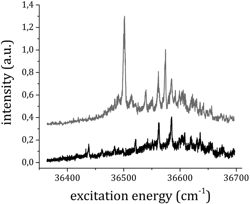 | ||
| Fig. 4 RE2PI spectra obtained by measuring the ion signal at the TOF corresponding to the 1:1+ (top) and 1:2+ ions (bottom). The traces have been vertically shifted for simpler comparison. | ||
The origin band of the S1–S0 electronic transition of the 1:1 complex is assigned to the strong peak at 36501 cm−1 (in perfect agreement with previous experiments27,28), which is blue shifted by 117 cm−1 with respect to the corresponding transition of the anisole monomer. The present data suggest the assignment of the origin band of the S1–S0 excitation spectrum of the 1:2 complex electronic transition to the rather weak peak at 36437 cm−1 (blue shifted by 53 cm−1 with respect to the corresponding transition of the anisole monomer and red shifted by 64 cm−1 with respect to that of the 1:1 adduct). No signals were observed in the RE2PI spectrum for excitation below 36400 cm−1 either at the 1:1 or 1:2 adducts mass channel. The observed shifts are reproduced by that obtained by means of the SCS-ADC(2) method. The calculated S1–S0 electronic transition of the 1:1 complex is 37928 cm−1, in very good agreement with the experimentally observed band, blue shifted by 126 cm−1 with respect to the band of the isolated anisole, calculated at the same level of theory. The 1:2 complex S1–S0 origin band was calculated at 37899 cm−1, blue shifted by 97 cm−1, and red shifted by 29 cm−1 with respect to the corresponding calculated transitions of the anisole monomer and the 1:1 adduct, respectively. It must be noted that in earlier work on the anisole–CO2 complex, the origin band for the REMPI spectrum of the 1:2 adduct was indicated as red shifted by 216 cm−1 with respect to the origin band of the anisole.28 Quite remarkably, this assignment was reported only marginally in the text and not further discussed or graphically presented.
All the results clearly indicate a red shift for the electronic transition of the 1:2 adduct with respect to that of the 1:1 adduct, whereas the electronic transition of the 1:1 adduct with respect to the anisole monomer is significantly blue shifted. These results are perfectly compatible with the reported geometry for the 1:2 complex that exhibits two completely different binding sites for the CO2 molecules. Conversely, they suggest that in the excited state the second binding site for CO2, positioned above the aromatic plane, has a much higher degree of stabilization than the one on the side that, consequently, is destabilized with respect to the ground state.
Once the origin bands of the S1–S0 electronic transitions were assigned, we set up the two-color 1 + 1′ RE2PI experiment. First, the pump laser was set in resonance with the frequency (36501 cm−1) of the origin band of the 1:1 adduct and the photon frequency of the probe laser was varied while monitoring the mass channel of the anisole+ fragment. The results are shown in Fig. 5, where it is evident how the anisole+ ion signal starts to increase significantly just above 68300 ± 100 cm−1 total excitation energy.
 | ||
| Fig. 5 The anisole+ ion signal intensity is reported as a function of the total excitation energy provided to the system. The pump laser is held in resonance with the S1–S0 origin band for the 1:1 adduct at 36501 cm−1 while the probe photon energy is tuned in the range of 31250–33000 cm−1. | ||
The ionization potential (IP) of the 1:1 adduct was determined using electron imaging in the RE2PI experiments carried out in the (ion-)electron imaging – TOF spectrometer working under velocity mapping conditions. It has already been shown that this approach provides very good results for anisole IP determination.30 In the present case, the pump laser was held in resonance with the origin transition of the S1–S0 electronic transition of the 1:1 adduct, at 36501 cm−1. The probe laser energy was instead varied between 31300 and 32100 cm−1 and for each value of the probe energy a photoelectron image of about 5000 shots was recorded (an example is reported in Fig. 6a). The images were then transformed into photoelectron velocity spectra by a numerical elaboration procedure using the polar onion peeling algorithm.47 The result is shown in Fig. 6b. We report a graph (Fig. 7) of the total excitation energy provided by the two photons absorbed against the squared radius of the outer circle of each image. By extrapolation to the radius of the image equal to zero, it is possible to determine the IP of the 1:1 adduct as 66659 ± 30 cm−1.
 | ||
| Fig. 6 3D graphical representation of the 1:1 adduct photoelectron image obtained under velocity mapping conditions (panel a) from a RE2PI experiment with total excitation energy 68505 cm−1 (36501 + 32004 cm−1) by averaging 5000 laser shots, and the associated photoelectron velocity spectrum (panel b). | ||
 | ||
| Fig. 7 The total excitation energy relative to each photoelectron image plotted against the squared radius of the outer circle in the image of the photoelectron distribution (Fig. 5a). The inset shows the resonance at 36501 cm−1 in the total electron yield as a function of the first photon frequency in the RE2PI experiment. | ||
To make sure that we were effectively dealing with photoelectrons emitted from the 1:1 adduct, the total photoelectron yield was measured while scanning the pump laser frequency. The result is shown in the inset of Fig. 7, where a peak at 36501 cm−1 is present, corresponding to the origin band of the 1:1 adduct electronic transition, already measured in the mass-selected spectrum. Compared to the IP of the bare anisole30,48 the measured IP of the 1:1 complex is about 260 cm−1 higher. This result can be easily interpreted on the basis of simple electrostatic arguments. The main interaction between anisole and CO2 in the 1:1 adduct involves the positively charged carbon atom on CO2 and the negatively charged oxygen of the anisole. When ionization occurs, the anisole ring becomes positively charged and electron density moves from the oxygen atom to the ring, making the intermolecular bond weaker. Hence, the complex in the ionic state is relatively less stable with respect to the neutral ground state. This result is in full agreement with the theoretical predictions that suggest an increase in the ionization potential upon formation of the 1:1 adduct (vertical transition) by 1.0 kcal mol−1 (350 cm−1) at the DFT level and 1.05 kcal mol−1 (367 cm−1) when calculated with MP2/cc-pVTZ.
In order to measure the IP and BE of the 1:2 adduct, the most intense transitions observed in the RE2PI spectrum of this complex at 36562 and 36585 cm−1 were used: the 1:1+ ion production was monitored while changing the pump laser frequency between 36550 and 36603 cm−1. In this spectral range three peaks are present, one assigned to the 1:1 adduct (36573 cm−1) and two to the 1:2 adduct (36562 and 36585 cm−1). The experiment was repeated for different probe laser frequencies, from 31250 to 32700 cm−1, and the corresponding spectra are reported in Fig. 8. The intensity of both the peaks assigned to the 1:2 adduct was plotted against the total excitation energy as reported in Fig. 9, where it is evident that the production of 1:1+ rises considerably above 68300 ± 100 cm−1. This value is equal to the appearance energy for anisole ions from the dissociative ionization of the 1:1 adduct. The loss of a single CO2 molecule can take place from two different binding points of the 1:2 adduct. The binding energy in the two sites is almost equivalent in the two cases, according to our ground state calculations. However, there is a clear indication that the out-of-plane site becomes energetically favored in the excited state, as deduced from the spectral shift of the S1–S0 origin band for the different adducts. A similar trend is possible in the ionic state, as in both cases the electron density on the aromatic system decreases, similarly to the S1 excitation case.
 | ||
| Fig. 8 REMPI spectra with pump laser scanning in the range of 36550–36604 cm−1 while the probe laser was set at 31252, 31375, 31498, 31632, 31748, 31875, 32002, 32130, 32260, 32522 and 32789 cm−1 (bottom to top traces). | ||
 | ||
| Fig. 9 The dissociation onset for the ionic 1:2 anisole–CO2 adduct: the intensity of the peaks due to the appearance of the 1:1 anisole–CO2+ ion at 36562 cm−1 (empty circles) and 36585 (filled circles) from RE2PI data of Fig. 7 (peaks assigned to the 1:2 anisole–CO2 adduct) is plotted against the total excitation energy. For comparison, data relative to the dissociation of the 1:1 anisole–CO2 adduct (already shown in Fig. 5) are reported as well (crosses). | ||
Moreover, another indication of the sensitivity of the second binding site to the change in electron density in the different states derives from the simple observation of the relative Franck–Condon factors in the vibronic spectrum of the two adducts in the RE2PI mass selected spectra (see Fig. 3). Therefore, this threshold for dissociation must be discussed bearing in mind the possibility that the ionic dissociation of the 1:2 adduct could lead to a 1:1+ adduct in a geometry different from that obtained simply by photoionization of the 1:1 system. In order to verify this interpretation, we have performed the structure optimization of the 1:1 cation using the DFT-D3 method starting from the structure of the 1:2 adduct and removing one or the other CO2 molecule. Two different minima were identified, the one associated with the CO2 molecule starting from the secondary, out-of-plane, position being the most stable by 1.27 kcal mol−1 (444 cm−1).
We did not succeed in the determination of the 1:2 adduct IP. In the photoelectron imaging experiment only a very weak signal is produced by the pump laser excitation in resonance with the transitions observed in the RE2PI experiment, without any sharp features. The simultaneous non-resonant absorption and ionization of other chemical species could lead to a similar result. In fact, when we repeated the measurement of the total electronic yield as a function of the excitation photon energy, as for the case of the 1:1 adduct, no resonance in the photoelectron spectrum was observed. This result can be understood by the blue shift of the transitions relative to the different anisole–CO2 adducts with respect to the corresponding ones of anisole (therefore, in any experiment we are above the threshold for excitation and ionization of anisole itself, by far the most abundant chromophore in the sample). Another relevant factor can be the formation efficiency of the different adducts and the possibly smaller Franck–Condon factors for the 1:2 adduct. Instead, in mass selected experiments, appropriately gating the ion signals, the background ionization events can be easily removed and the spectrum of the 1:2 adduct is readily observed. The same kind of problems was probably the cause of the lack of observation for the onset of production of the anisole+ ion upon three-body dissociation of the ionized 1:2 anisole–CO2 adduct.
The present results allowed us to build a complete correlation scheme for the electronic levels of bare anisole and anisole–CO2. The first relevant quantity we derive is the apparent binding energy of the 1:1 adduct in the ionic state, 1841 ± 130 cm−1. It is obtained as the difference between the appearance energy of the anisole ion fragments and the IP of the 1:1 adduct. Then, the relative energy of the corresponding levels of the bound and non-bound systems is set and the binding energies of the 1:1 adduct in the neutral ground S0 and first excited S1 states are readily calculated as 1901 ± 105 and 1784 ± 106 cm−1. The corresponding diagram is reported in Fig. 10.
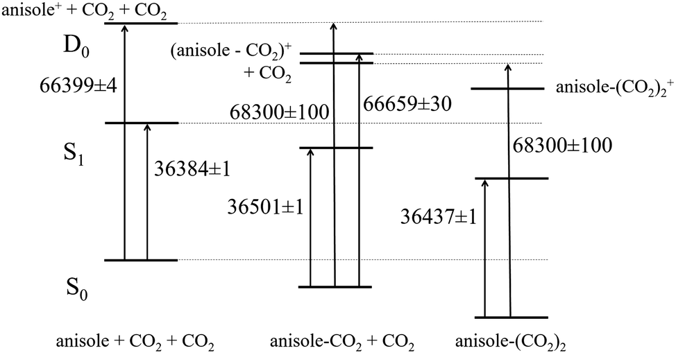 | ||
| Fig. 10 The correlation diagram between the corresponding levels of anisole (left), anisole–CO2 (center), and (anisole–CO2)2 (right) adducts obtained from the experimental results. Energies are given in wavenumbers. | ||
The experimental S0 value is about 1000 cm−1 higher than the calculated one (811 cm−1). A similar discrepancy was encountered also in the study of the anisole dimer, where the first observed dissociation channel in the ionic state resulted in the determination of the ground S0 state dissociation energy being about 2000 cm−1 higher than the calculated value.25 Further analysis revealed that the dissociation process was already starting at much lower energies, even if with a much lower efficiency.26 We believe that all these differences can be explained as a consequence of the Franck–Condon factor for the S0 → S1 → ion excitation process: the aromatic ring dimensions are increasing with electronic excitation/ionization and the aromatic C![[double bond, length as m-dash]](https://www.rsc.org/images/entities/char_e001.gif) C stretching modes have a vibrational frequency of around 1000 cm−1. Therefore, it is quite likely that the highly excited vibrational state of the ion we produce in order to promote dissociation has some CC bond excitation character, together with intermolecular vibrational states. It is then possible that the resulting anisole fragments are produced in the first CC vibrational excited state. In case of the anisole dimer, the excited S1 state has an excitonic nature involving both units. Hence, it is possible that both fragments are excited in the CC stretching modes when the dimer is projected in the ionic state. The subsequent dissociation process takes place preserving the internal excitation of the fragments. If this is the case for the anisole–CO2 adduct, the real onset for dissociation in the ionic state leading to vibrationless fragments should be placed at about 67300 cm−1, leading to the binding energy values being in very good agreement with computational data: 641, 784, and 901 cm−1 for the ionic, S1 and S0 states, respectively. On the assumption that our hypothesis of resulting vibrationally excited anisole fragments from dissociation is correct, the error in these values is in the order of 130 cm−1 (0.4 kcal mol−1).
C stretching modes have a vibrational frequency of around 1000 cm−1. Therefore, it is quite likely that the highly excited vibrational state of the ion we produce in order to promote dissociation has some CC bond excitation character, together with intermolecular vibrational states. It is then possible that the resulting anisole fragments are produced in the first CC vibrational excited state. In case of the anisole dimer, the excited S1 state has an excitonic nature involving both units. Hence, it is possible that both fragments are excited in the CC stretching modes when the dimer is projected in the ionic state. The subsequent dissociation process takes place preserving the internal excitation of the fragments. If this is the case for the anisole–CO2 adduct, the real onset for dissociation in the ionic state leading to vibrationless fragments should be placed at about 67300 cm−1, leading to the binding energy values being in very good agreement with computational data: 641, 784, and 901 cm−1 for the ionic, S1 and S0 states, respectively. On the assumption that our hypothesis of resulting vibrationally excited anisole fragments from dissociation is correct, the error in these values is in the order of 130 cm−1 (0.4 kcal mol−1).
Similar arguments apply to the 1:2 adduct ionic dissociation dynamics. In this case, the complete diagram of the relevant levels cannot be specified, as we were not able to measure the IP of the 1:2 adduct and a question arises regarding the possible different conformers existing for the 1:1 cation. Nevertheless, the complete available data set of the different systems allows us to set well-defined boundaries for the stabilization energy of this adduct as well. It requires a few assumptions based on experimental evidence and calculations. Our model for the conformation of the 1:2 adduct has already been presented and calculations show that the two binding site properties are not correlated. We can also safely assume that, in agreement with computational data, the 1:1+ ion formed by dissociative ionization of the 1:2 adduct has energy lower than that formed by direct ionization of the 1:1 adduct. In fact, as two different reaction channels are available, a larger coordinate space is explored and the reaction should lead to a final product with energy not higher than that obtained by direct ionization of the 1:1 adduct. On the basis of the experimental data, the binding energies for the second CO2 unit to the 1:1 adduct in the neutral ground state and in the ground ionic state are equal. If the 1:1+ ion is produced in the same conformation by both processes, then the binding energy for the second CO2 unit to the 1:1 cation is equal to the binding energy of the first unit to the anisole cation (641 cm−1). Conversely, if different 1:1+ conformers are possible, the binding energy for the second CO2 unit (the one above the aromatic plane) is larger. An energy splitting for the different conformations of the 1:1 cation in the order of 1 kcal mol−1, as suggested by the calculations, would lead to a very good agreement between the experimental and theoretical binding energies for the 1:2 adduct in the ground state: 1895 and 1815 cm−1, respectively. Much larger energy splitting for the different conformers of the 1:1+ adduct would result in exceedingly large values of the binding energy of the second CO2 unit to the 1:1 system. Therefore, we conclude that both experiments and calculations point to a 350 ± 120 cm−1 – 1.0 ± 0.3 kcal mol−1 energy difference between the different conformers of the 1:1+ adduct. Finally, we can evaluate the energy for complete dissociation of the 1:2 adduct in the S0 and S1 states as 1892 and 1839 cm−1, respectively, with a minimum accuracy of 250 cm−1 – 0.7 kcal mol−1.
Conclusions
We have obtained a detailed description of the interaction between CO2 and anisole in a gas phase, isolated, molecular cluster. This system represents a challenging test for the presently available experimental and theoretical methods for the characterization of weakly bound molecular complexes. The results, evaluated in the framework of previous studies on anisole clusters, show a very good agreement between experimental and theoretical data. Therefore, our understanding of the intermolecular processes controlling the stabilization of these small systems is quite satisfactory, as summarized below. This represents a fundamental step in order to build up knowledge on more large and complicated systems where either an explicit or a statistically averaged representation of the interaction between all the different chemical partners is needed.The potential energy surface for these adducts is rather complicated. Two preferential binding sites for CO2 on the anisole exist: one in the anisole plane, along the methoxy group, the other above the anisole plane, close to the methoxy group. We have experimentally studied both the 1:1 and 1:2 clusters in the theoretically predicted most stable ground state conformation. The nature of the interactions in the 1:2 cluster was studied by means of the DFT-SAPT method, which provides decomposition of the interaction energy. It was found that electrostatics and dispersion contribute by approximately the same amount. The first CO2 binding site (the one occupied in the 1:1 complex) exhibits the highest contribution of electrostatics because of direct involvement of the lone pairs on the anisole oxygen. It is also the electrostatic component that determines the geometry of the cluster. Also, we were able to provide information on the excited state properties of the systems. We have determined, both experimentally and theoretically, the binding energy for the 1:1 and 1:2 adducts in the different electronic states. By direct ionization of the 1:1 adduct or by dissociative ionization of the 1:2 adduct we obtain different 1:1+ conformers, as the detachment of the different CO2 units allows access to a large potential energy interval of the system. The interaction energy in the two interaction sites changes in the different electronic states and their stability order is possibly reversed.
Conflicts of interest
There are no conflicts to declare.Acknowledgements
Financial support from the Italian Government (2010ERFKXL), EU (RII3-CT-2003-506350), University of Florence and the Czech Science Foundation (P208/12/G016) is gratefully acknowledged. The work is part of research project RVO: 61388963 of the IOCB AS CR. The technical assistance from LENS staff (R. Ballerini, A. Hajeb, M. De Pas, A. Montori and M. Giuntini) was essential for the setup and the maintenance of the experimental facility. The authors thank Dr B. Howes (University of Florence) for carefully reading the manuscript.References
- J. D. der Waals, PhD thesis, University of Leiden, 1873.
- J. E. Jones, Proc. R. Soc. London, Ser. A, 1924, 106, 463–477 CrossRef CAS.
- R. A. Buckingham, Proc. R. Soc. London, Ser. A, 1938, 168, 264–283 CrossRef CAS.
- J. Řezáč and P. Hobza, Chem. Rev., 2016, 116, 5038–5071 CrossRef PubMed.
- P. Hobza, Acc. Chem. Res., 2012, 45, 663–672 CrossRef CAS PubMed.
- J. A. Frey, C. Holzer, W. Klopper and S. Leutwyler, Chem. Rev., 2016, 116, 5614–5641 CrossRef CAS PubMed.
- M. Becucci and S. Melandri, Chem. Rev., 2016, 116, 5014–5037 CrossRef CAS PubMed.
- A. K. Samanta, Y. Wang, J. S. Mancini, J. M. Bowman and H. Reisler, Chem. Rev., 2016, 116, 4913–4936 CrossRef CAS PubMed.
- F. Mazzoni, M. Becucci, J. Řezáč, D. Nachtigallová, F. Michels, P. Hobza and K. Müller-Dethlefs, Phys. Chem. Chem. Phys., 2015, 17, 12530–12537 RSC.
- D. W. Pratt, Annu. Rev. Phys. Chem., 1998, 49, 481–530 CrossRef CAS PubMed.
- D. W. Pratt, Handbook of High-resolution Spectroscopy, John Wiley & Sons, Ltd, Chichester, UK, 2011, pp. 1291–1320 Search PubMed.
- K. Müller-Dethlefs and M. Riese, Handbook of High-resolution Spectroscopy, John Wiley & Sons, Ltd, Chichester, UK, 2011, pp. 1713–1740 Search PubMed.
- J. E. Braun, T. L. T. L. Grebner and H. J. Neusser, J. Phys. Chem. A, 1998, 102, 3273–3278 CrossRef CAS.
- H. J. Neusser and K. Siglow, Chem. Rev., 2000, 100, 3921–3942 CrossRef CAS PubMed.
- M. Becucci, G. Pietraperzia, M. Pasquini, G. Piani, A. Zoppi, R. Chelli, E. Castellucci and W. Demtroeder, J. Chem. Phys., 2004, 120, 5601–5607 CrossRef CAS PubMed.
- J. W. Ribblett, W. E. Sinclair, D. R. Borst, J. T. Yi and D. W. Pratt, J. Phys. Chem. A, 2006, 110, 1478–1483 CrossRef CAS PubMed.
- M. Pasquini, N. Schiccheri, G. Piani, G. Pietraperzia, M. Becucci, M. Biczysko, M. Pavone and V. Barone, J. Phys. Chem. A, 2007, 111, 12363–12371 CrossRef CAS PubMed.
- M. Heger, J. Altnöder, A. Poblotzki, M. A. Suhm, J. G. Hill, M. A. Suhm, R. W. Larsen, J. Bloino and V. Barone, Phys. Chem. Chem. Phys., 2015, 17, 13045–13052 RSC.
- G. Piani, M. Pasquini, G. Pietraperzia, M. Becucci, A. Armentano and E. Castellucci, Chem. Phys. Lett., 2007, 434, 25–30 CrossRef CAS.
- M. Biczysko, G. Piani, M. Pasquini, N. Schiccheri, G. Pietraperzia, M. Becucci, M. Pavone and V. Barone, J. Chem. Phys., 2007, 127, 144303 CrossRef PubMed.
- B. M. Giuliano, A. Maris, S. Melandri and W. Caminati, J. Phys. Chem. A, 2009, 113, 14277–14280 CrossRef CAS PubMed.
- G. Pietraperzia, M. Pasquini, N. Schiccheri, G. Piani, M. Becucci, E. Castellucci, M. Biczysko, J. Bloino and V. Barone, J. Phys. Chem. A, 2009, 113, 14343–14351 CrossRef CAS PubMed.
- N. Schiccheri, M. Pasquini, G. Piani, G. Pietraperzia, M. Becucci, M. Biczysko, J. Bloino and V. Barone, Phys. Chem. Chem. Phys., 2010, 12, 13547–13554 RSC.
- M. Pasquini, G. Pietraperzia, G. Piani and M. Becucci, J. Mol. Struct., 2011, 993, 491–494 CrossRef CAS.
- F. Mazzoni, M. Pasquini, G. Pietraperzia and M. Becucci, Phys. Chem. Chem. Phys., 2013, 15, 11268–11274 RSC.
- J. Řezáč, D. Nachtigallová, F. Mazzoni, M. Pasquini, G. Pietraperzia, M. Becucci, K. Müller-Dethlefs and P. Hobza, Chemistry, 2015, 21, 6637 CrossRef.
- C. G. Eisenhardt, M. Pasquini, G. Pietraperzia and M. Becucci, Phys. Chem. Chem. Phys., 2002, 4, 5590–5593 RSC.
- A. S. Gemechu, L. J. H. Hoffmann, S. Marquardt, C. G. Eisenhardt, H. Baumgärtel, R. Chelli, G. Cardini and S. Califano, Z. Phys. Chem., 2004, 218, 123–154 CrossRef CAS.
- C. G. Eisenhardt, G. Pietraperzia and M. Becucci, Phys. Chem. Chem. Phys., 2001, 3, 1407–1410 RSC.
- M. Pasquini, G. Piani, F. Mazzoni, G. Pietraperzia and M. Becucci, J. Mol. Struct., 2011, 993, 510–515 CrossRef CAS.
- M. Elstner, P. Hobza, T. Frauenheim, S. Suhai and E. Kaxiras, J. Chem. Phys., 2001, 114, 5149–5155 CrossRef CAS.
- S. Grimme, J. Antony, S. Ehrlich and H. Krieg, J. Chem. Phys., 2010, 132, 154104 CrossRef PubMed.
- S. Grimme, S. Ehrlich and L. Goerigk, J. Comput. Chem., 2011, 32, 1456–1465 CrossRef CAS PubMed.
- L. Goerigk, H. Kruse and S. Grimme, ChemPhysChem, 2011, 12, 3421–3433 CrossRef CAS PubMed.
- P. Jurečka, J. Šponer, J. Černý, P. Hobza, A. Abu-Riziq, B. Crews and M. S. de Vries, Phys. Chem. Chem. Phys., 2006, 8, 1985–1993 RSC.
- J. Řezáč, Y. Huang, P. Hobza and G. J. O. Beran, J. Chem. Theory Comput., 2015, 11, 3065–3079 CrossRef PubMed.
- G. Jansen, Wiley Interdiscip. Rev.: Comput. Mol. Sci., 2014, 4, 127–144 CrossRef CAS.
- J. Řezáč and P. Hobza, J. Chem. Theory Comput., 2011, 7, 685–689 CrossRef PubMed.
- C. Hättig, Adv. Quantum Chem., 2005, 50, 37–60 CrossRef.
- S. Grimme, J. Chem. Phys., 2003, 118, 9095–9102 CrossRef CAS.
- D. Rappoport and F. Furche, J. Chem. Phys., 2010, 133, 134105 CrossRef PubMed.
- A. Schäfer, C. Huber and R. Ahlrichs, J. Chem. Phys., 1994, 100, 5829–5835 CrossRef.
- TURBOMOLE V6.2 2010, a development of University of Karlsruhe and Forschungszentrum Karlsruhe GmbH, 1989-2007, TURBOMOLE GmbH, since 2007, available from http://www.turbomole.com.
- B. Aradi, B. Hourahine and Th. Frauenheim, J. Phys. Chem. A, 2007, 111, 5678–5684 CrossRef CAS PubMed.
- H. Werner, P. J. Knowles, G. Knizia, F. R. Manby and M. Schütz, Wiley Interdiscip. Rev.: Comput. Mol. Sci., 2012, 2, 242–253 CrossRef CAS.
- J. Řezáč, J. Comput. Chem., 2016, 37, 1230–1237 CrossRef PubMed.
- S. Manzhos and H.-P. Loock, Comput. Phys. Commun., 2003, 154, 76–87 CrossRef CAS.
- M. Pradhan, C. Li, J. L. Lin and W. B. Tzeng, Chem. Phys. Lett., 2005, 407, 100–104 CrossRef CAS.
Footnote |
| † In the following part of the manuscript the different anisole–carbon dioxide adducts will be labeled as m:n where m and n refer to the number of anisole and carbon dioxide units present, respectively. |
| This journal is © the Owner Societies 2017 |