 Open Access Article
Creative Commons Attribution 3.0 Unported Licence
Capture of Xe and Ar atoms by quantized vortices in 4He nanodroplets†
François
Coppens
 *ab,
Francesco
Ancilotto
cd,
Manuel
Barranco
abef,
Nadine
Halberstadt
ab and
Martí
Pi
ef
aUniversité de Toulouse, UPS, Laboratoire Collisions Agrégats Réactivité, IRSAMC, F-31062 Toulouse, France. E-mail: francois.coppens@irsamc.ups-tlse.fr
bCNRS, UMR 5589, F-31062 Toulouse, France
cDipartimento di Fisica e Astronomia ‘Galileo Galilei’ and CNISM, Università di Padova, via Marzolo 8, 35122 Padova, Italy
dCNR-IOM Democritos, via Bonomea 265, 34136 Trieste, Italy
eFacultat de Física, Departament FQA, Universitat de Barcelona, Diagonal 645, 08028 Barcelona, Spain
fInstitute of Nanoscience and Nanotechnology (IN2UB), Universitat de Barcelona, Barcelona, Spain
First published on 4th September 2017
Abstract
We present a computational study, based on time-dependent Density Functional theory, of the real-time interaction and trapping of Ar and Xe atoms in superfluid 4He nanodroplets either pure or hosting quantized vortex lines. We investigate the phase-space trajectories of the impurities for different initial conditions and describe in detail the complex dynamics of the droplets during the capture of the impurities. We show that the interaction of the incoming atom with the vortex core induces large bending and twisting excitations of the vortex core lines, including the generation of helical Kelvin waves propagating along the vortex core. We have also calculated the stationary configurations of a 4He droplet hosting a 6-vortex array whose cores are filled with Ar atoms. As observed in recent experiments, we find that doping adds substantial rigidity to the system, such that the doped vortex array remains stable, even at low values of the angular velocities where the undoped vortices would otherwise be pushed towards the droplet surface and be expelled.
1 Introduction
It is well established that helium droplets can readily capture in their interior almost any atom or molecule interacting with them, as first shown for the case of Ne atoms,1 with the notable exception of alkali2 and some alkaline-earth3 atoms. This property, together with the extremely low temperature (T) achieved in helium droplets – of the order of 0.4 K – makes them the perfect ultracold and inert environment for hosting and studying isolated atoms and molecules, which is at the basis of current applications of helium droplets for spectroscopic studies of atoms and molecules. Besides, the superfluid nature of helium facilitates binary encounters of atoms/molecules in the bulk of the droplet while absorbing the energy released upon recombination, making possible chemical reactions which would not otherwise occur in the gas phase. These unique properties of helium droplets have had a huge impact on their study.4–8The pickup of Ar, Kr and Xe atoms in the gas phase by 4HeN droplets with N > 103 atoms produced by nozzle beam expansions was described about twenty years ago by Toennies and coworkers.9 In these experiments, the droplets in the helium beam were deflected by impacting with a secondary beam made of rare gas atoms.
Recently, a technique has been introduced to determine the size of large He droplets (N > 105). It is based on the attenuation of a continuous droplet beam through collisions with Ar atoms at room temperature.10 The pickup chamber of the droplet beam apparatus is filled with argon gas and the helium droplets experience multiple, isotropic collisions with the Ar atoms on their way towards the detection chamber. Large helium droplets could also be doped in this way. This method, using Xe atoms, has been instrumental for detecting and imaging quantized vortex arrays in helium droplets.11,12 Xe atoms were used in these experiments because of their large sensitivity to the X-ray coherent diffractive imaging employed to detect them within the helium droplets. Experiments with large superfluid helium droplets are reviewed in a recent publication.14
The impurity–droplet interaction in the presence of vortices is also relevant as the first stage of a more complex process leading to the formation of nanowires, see e.g.ref. 15–18. Long filaments made of micrometer-sized solid hydrogen particles trapped on quantized vortex cores were used to directly image the vortex reconnection between quantized vortices in superfluid helium.19
The impact and capture of impurities interacting with pure helium droplets have been addressed recently within time-dependent density functional theory (TDDFT). Real-time simulations have been carried out for heliophobic20 (Cs) and heliophilic21 (Ne) atoms. In addition to the TDDFT equation for 4He, heavy impurities are treated as classical particles using Newton's equation of motion, whereas a time-dependent Schrödinger equation has been used in the case of light impurities within the mean field model.21,22 A comparison between the results for head-on collisions of Cs and Xe atoms – heliophobic and heliophilic atoms of similar mass – has been presented in ref. 23.
In this work, we present the results obtained within TDDFT for the collision and capture of Xe and Ar atoms by a 4He1000 droplet at different kinetic energies and impact parameters. Special attention is paid to the time-dependent interaction of Xe and Ar atoms with helium nanodroplets hosting vortex lines, and to the effect of multiply-doped vortex arrays in large helium droplets.
Due to the heavy computational cost of the TDDFT simulations presented here, we address only a few facets of the capture process that we consider of experimental relevance rather than carrying out a systematic study of the process. In particular:
˙ We study the capture of Xe atoms by a 4He nanodroplet, both for head-on collisions and for different impact parameters, with velocities ranging from thermal values up to several hundred m s−1. The results of peripheral collisions with different values of the impact parameter are used to estimate the cross section for the Xe capture.
˙ We study how a Xe atom dynamically interacts with a droplet hosting a vortex line, under different initial conditions resulting in different velocity regimes of the impurity as it collides with the vortex core: (i) a Xe atom initially at rest on the droplet surface and sinking under the effect of solvation forces; and (ii) a head-on collision of a moving Xe or Ar atom against the 4He nanodroplet.
˙ We study the stationary state of a large 4He15000 droplet hosting a ring of six vortex lines, doped with Ar atoms completely filling all six vortex cores. This is the simplest system that mimics those experimentally described in ref. 11, where doped vortex arrays embedded in rotating 4He microdroplets have been imaged.
Multimedia materials accompany this paper, showing the real-time dynamics of several impact/capture processes described here. These materials are presented in the ESI† document. They constitute an important part of this work, since often it is only by viewing how a complex microscopic process unfolds in real time that one can catch important physical details which would otherwise escape in a written account.
2 Theoretical approach
The DFT model of liquid helium, which describes the nuclear degrees of freedom quantum mechanically, has emerged as the only viable method to address the experimentally studied large helium droplets. Its use constitutes a compromise between the accuracy of “ab initio” methods (like quantum Monte Carlo methods24) and numerical feasibility.25 Its essential features are recalled here for the sake of completeness.Within DFT, the total energy E of a 4HeN droplet at zero temperature is written as a functional of the 4He atom density ρ(r)
 | (1) |
As in recent applications of the TDDFT approach,23,26–30 we use the correlation energy density functional ![[scr E, script letter E]](https://www.rsc.org/images/entities/char_e140.gif) c proposed in ref. 31. This functional has a finite range and includes non-local effects. Both aspects are needed to describe the response of the liquid at the Angström-scale. Note that a zero-range density functional has been recently applied to the study of inelastic scattering of xenon atoms by quantized vortices in superfluid liquid 4He.32 Particle–vortex collisions in thermal superfluid 4He have also been addressed.33
c proposed in ref. 31. This functional has a finite range and includes non-local effects. Both aspects are needed to describe the response of the liquid at the Angström-scale. Note that a zero-range density functional has been recently applied to the study of inelastic scattering of xenon atoms by quantized vortices in superfluid liquid 4He.32 Particle–vortex collisions in thermal superfluid 4He have also been addressed.33
It is customary to define an order parameter Ψ (often called the effective wave function) as  . The kinetic energy of the fictitious system of non-interacting particles is thus
 | (2) |
 | (3) |
![[scr S, script letter S]](https://www.rsc.org/images/entities/char_e532.gif) (r,t)], the particle current density is
(r,t)], the particle current density is | (4) |
that fulfills
but in general
Thus, in the zero temperature DFT approach, liquid helium flows irrotationally. Liquid helium is compressible, a property that – at variance with simpler approaches – is taken into account in the DFT method.
In the case of stationary states, Ψ(r,t) = Ψ0(r)eiμ4t/ħ and eqn (3) becomes
 | (5) |
The effect of heavy impurities like Ar and Xe atoms embedded inside He droplets is incorporated as an external field. The impurity–droplet interaction is described within the pairwise sum approximation
 | (6) |
 | (7) |
This static DFT equation is solved by the imaginary time method in Cartesian coordinates. The calculation is full 3D with no a priori imposed symmetry. A key tool for the implementation of the method is the use of fast-Fourier techniques (FFT)35 to calculate the convolutions needed to obtain some of the contributions to the total energy of the impurity–droplet complex and the mean field potentials appearing in the EL equations. Densities, wave functions and differential operators are discretized on a Cartesian grid. The spatial grid intervals most often used in the applications are in the 0.3–0.4 Å range. The differential operators (first and second derivatives) are represented by 13-point formulas.
Once the static configuration has been obtained for a given impurity, the dynamics starts by imparting a velocity v0 to the impurity, initially placed at a chosen location rI0. Ψ(r,t) is thus evolved following the TDDFT prescription and rI(t) according to Newton's equation of motion:
 | (8) |
Eqn (8) are solved using Hamming's predictor-modifier-corrector method36 using the same box and grid as for the static problem. In most cases, we have employed a time step of ∼0.5 fs. Hamming's method is not self-starting and requires the evaluation of the solution for a few initial time steps. They were obtained using a fourth-order Runge–Kutta–Gill algorithm.36
During the time evolution, some helium can be ejected off the droplet, eventually reaching the boundaries of the cell used in the simulations. If no action is taken, this material will re-enter the simulation cell from the other side (periodic boundary conditions are implied in our calculations due to the use of FFT), therefore spoiling the calculation. We have handled this problem by including an absorption potential into the time-dependent equation for helium.37 Note that this particle – and thus energy – leaking is physical: it represents helium atoms leaving the droplet and carrying away energy, although in a continuous way inherent to the DFT approach.
3 Results
The results presented in this work have been obtained using the 4He-DFT BCN-TLS computing package.383.1 Xe capture by vortex-free droplets
We have simulated head-on collisions of a Xe atom with a 4He1000 droplet at relative velocities v0 ranging from 200 to 600 m s−1. Fig. 1 displays the two-dimensional plots of the helium density for the highest value, v0 = 600 m s−1. This velocity is well above the range of velocities typically encountered in experiments.10–12 In spite of the appearance of disconnected helium density shown in the t = 87 ps frame, we have found that the Xe atom eventually turns around and is captured again inside the droplet even at that relatively high impact velocity. Note that the Xe impurity, even when it temporarily emerges from the bulk of the droplet, appears to be coated with a few 4He atoms, see the configuration at 87 ps.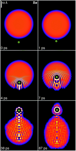 | ||
| Fig. 1 Dynamic evolution of a Xe atom (green dot) approaching the 4He1000 droplet from below at v0 = 600 m s−1. The corresponding time is indicated in each frame. Bright spots correspond to high density regions.39 | ||
Fig. 1 also shows the development of bow waves in the density profile, moving ahead of the impurity at supersonic velocity, and an incipient conic density wave front with its vertex at the Xe bubble. Similar conic shapes, characteristic of supersonic flows, are found when an impurity moves in bulk liquid helium. In the present case, the limited size of the droplet and the loss of kinetic energy during the first stages of the collision smooth out this front, making it just barely visible in the figure.
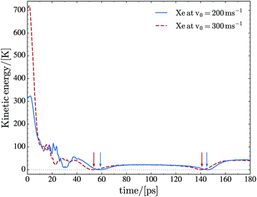
At low initial velocities of the impurity, we find that Xe moves back and forth inside the droplet. The turning points are not fixed, because the droplet deforms due to the displacement of the Xe atom and to the waves that are continuously emitted by the moving impurity (mainly in the direction of its motion), hit the droplet surface, and are reflected back inside it.23 This is shown in Fig. 2 at v0 = 200 and 300 m s−1. Thermal Xe atoms (v0 ∼ 240 m s−1) are used in the vortex imaging experiments,11,12 and the average droplet velocity as it travels through the pick-up chamber is about 170 m s−1,10 corresponding to relative collision velocities which are within the range investigated here. The kinetic energy gained by the Xe atom after the turning point at 140–150 ps is precisely due to the fact that the droplet is not a rigid object and reacts to the motion of the impurity. As a consequence, energy is transferred not only from the impurity to the droplet but also the other way around. We want to emphasize that the droplet experiences large deformations rather than large displacements; the velocity of the center of mass (COM) of the droplet is rather small (below 6 m s−1 for v0 = 200 and 300 m s−1 as well) due to the large mass difference between the impurity and the droplet.
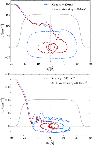
We have found that most of the energy is transferred from the Xe atom to the droplet in the first stages of the collision. This is why, for collisions in this kinetic energy range leading to Xe capture, the motion of the impurity inside the droplet is independent of the initial kinetic energy to a large extent. This is shown in Fig. 3, which displays the trajectory of Xe (Ar) in phase space for v0 = 200 (360) m s−1. The figure also shows similar trajectories in the case where a vortex is present in the droplet; these cases will be discussed later in this paper.
The kinetic energy lost by the impurity atom is partly deposited in the droplet, where it produces large deformations and sound waves, and partly carried away by prompt-emitted helium atoms. These are atoms with a significant kinetic energy which are expelled from the droplet early on in the collision process. Fig. 4 shows the number of atoms remaining in the simulation cell as a function of time for collisions with Xe at v0 = 200, 300 and 400 m s−1. Eventually, the energy deposited into the droplet should be lost by atom evaporation. The energy carried away by the ejected He atoms during the first 200 ps is collected in Table 1 for the head-on collisions described in this paper. For comparison, the calculated binding energy of a helium atom in the 4He1000 droplet is 6.0 K. Note that helium atom ejection continues after 200 ps, with the droplet still being far from “thermalized” (equilibrated).
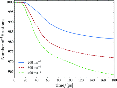 | ||
| Fig. 4 Number of He atoms remaining in the droplet as a function of time for the Xe against 4He1000 collision at v0 = 200, 300 and 400 m s−1. | ||
| Species | v 0 (m s−1) | N e | E e (K) |
|---|---|---|---|
| Xe | 200 | 18 | 19 |
| 300 | 28 | 23 | |
| 400 | 37 | 30 | |
| Ar | 360 | 16 | 22 |
In the case of heavy dopants, it is possible to obtain a simple expression for their capture cross section. Defining
 | (9) |
 | (10) |
![[small script l]](https://www.rsc.org/images/entities/char_e146.gif) cr is the largest relative angular momentum leading to the impurity capture. For a given energy,
cr is the largest relative angular momentum leading to the impurity capture. For a given energy, ![[small script l]](https://www.rsc.org/images/entities/char_e146.gif) cr is determined by carrying out simulations with different impact parameters b using
cr is determined by carrying out simulations with different impact parameters b using ![[small script l]](https://www.rsc.org/images/entities/char_e146.gif) = μv0b/ħ. We have done it for Xe at v0 = 200 m s−1. Fig. 5 shows the simulation corresponding to the largest impact parameter among the ones we have calculated which led to Xe capture, b = 20.3 Å, and Fig. 6 shows the simulation corresponding to the smallest one which led to Xe deflection, b = 22.2 Å. The radius of the droplet, which is defined as R = r0N1/3 with r0 = 2.22 Å, is 22.2 Å for N = 1000. Hence, at this energy – well within the thermal conditions of the experiment – the cross section for Xe capture is very similar to the geometric droplet cross section.
= μv0b/ħ. We have done it for Xe at v0 = 200 m s−1. Fig. 5 shows the simulation corresponding to the largest impact parameter among the ones we have calculated which led to Xe capture, b = 20.3 Å, and Fig. 6 shows the simulation corresponding to the smallest one which led to Xe deflection, b = 22.2 Å. The radius of the droplet, which is defined as R = r0N1/3 with r0 = 2.22 Å, is 22.2 Å for N = 1000. Hence, at this energy – well within the thermal conditions of the experiment – the cross section for Xe capture is very similar to the geometric droplet cross section.
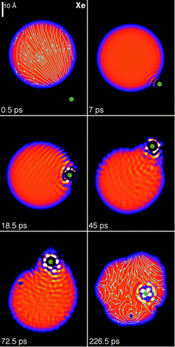 | ||
| Fig. 5 Dynamic evolution of a Xe atom (green dot) approaching the 4He1000 droplet from below at v0 = 200 m s−1 with impact parameter b = 20.3 Å. The corresponding time is indicated in each frame.39 | ||
The circulation lines of the superflow are displayed in two selected panels in Fig. 5 and 6. They show the flow pointing towards the approaching Xe atom at the beginning of the collision and the appearance of vortex loops in the droplet at the latest stages of the simulation. Vortex loops appear from local distortions of the droplet surface.28 The circulation lines displayed in the figures of this work have been drawn inside the region where the density is above 0.5ρ0 (with ρ0 = 0.0218 Å−3), which defines the dividing surface of the droplet.
In peripheral collisions, not only energy but also angular momentum is deposited into the droplet, which allows visualizing the irrotational flow of the superfluid helium. In particular, for Xe at v0 = 200 m s−1 and b = 22.2 Å the initial angular momentum is 917ħ. This collision was followed for some 220 ps and produced the ejection of 15 He atoms, 5 of them attached to the Xe atom, see Fig. 6. After the collision, the Xe + 4He5 complex carries away 522 angular momentum units, while some 95 units are deposited in the droplet as vortex loops and capillary waves,40 see the bottom right panel of Fig. 5 and 6. The remaining angular momentum is taken away by the ejected helium atoms.
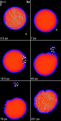 | ||
| Fig. 6 Dynamic evolution of a Xe atom (green dot) approaching the 4He1000 droplet from below at v0 = 200 m s−1 with impact parameter b = 22.2 Å. The corresponding time is indicated in each frame.39 | ||
3.2 Helium droplets hosting vortex lines
To determine the structure of a droplet hosting a singly-quantized linear vortex, we have started the imaginary time iteration from a helium density in which the vortex is “imprinted”. For this purpose, a vortex line along the z axis can be described by the effective wave function | (11) |
In the case represented by eqn (11), if the impurity is within the vortex core along a symmetry axis of the impurity–droplet complex, the effective wave function Ψ0(r) – before and after relaxation – is an eigenvector of the angular momentum operator ![[L with combining circumflex]](https://www.rsc.org/images/entities/i_char_004c_0302.gif) z = −ιħ∂/∂θ. The angular momentum of the droplet is then
z = −ιħ∂/∂θ. The angular momentum of the droplet is then
〈![[L with combining circumflex]](https://www.rsc.org/images/entities/i_char_004c_0302.gif) z〉 = 〈Ψ0(r)| z〉 = 〈Ψ0(r)|![[L with combining circumflex]](https://www.rsc.org/images/entities/i_char_004c_0302.gif) z|Ψ0(r)〉 = Nħ z|Ψ0(r)〉 = Nħ | (12) |
Different energy balances involving pure and doped droplets hosting vortices are defined:41–43
• Solvation energy of the impurity:
| SX = E(X@4HeN) − E(4HeN) |
• Vortex energy:
| EV = E(V@4HeN) − E(4HeN) |
• Binding energy of the impurity to the vortex:
| BX = SX − {E[(X + V)@4HeN] − E(V@4HeN)} |
The binding energy of the impurity to the vortex is the result of a delicate balance between terms which are individually much larger than their difference. It can thus be affected by relatively large inaccuracies. Within DFT, it has been found that the Xe atom is barely bound to the vortex line, with BXe ∼ 3–5 K.43,44
A critical angular velocity ωc exists above which nucleation of vortices with quantized velocity circulation in units of h/m4 occurs. The critical angular velocity for nucleating a vortex line along a diameter in a droplet made of N helium atoms is
 | (13) |
When the angular velocity is increased above ωc, larger amounts of angular momentum may be stored into the superfluid by increasing the number of nucleated vortices. The higher the angular velocity, the more packed the vortex array around the rotation axis. These vortices arrange themselves into ordered structures whose existence in bulk superfluid 4He was established long ago.45,46
To generate vortex arrays, we have worked in the fixed-droplet frame of reference (co-rotating frame at angular velocity ω), i.e. we look for solutions of the following EL equation:
{![[script letter H]](https://www.rsc.org/images/entities/char_e142.gif) [ρ] − ω [ρ] − ω![[L with combining circumflex]](https://www.rsc.org/images/entities/i_char_004c_0302.gif) z}Ψ(r) = μ4Ψ(r), z}Ψ(r) = μ4Ψ(r), | (14) |
 | (15) |
Fig. 7 shows the two-vortex stationary configuration of a 4He1000 droplet in the co-rotating frame at angular frequency ω = 0.175 K/ħ = 0.0229 ps−1. The angular momentum of this configuration is 〈![[L with combining circumflex]](https://www.rsc.org/images/entities/i_char_004c_0302.gif) z〉 = 1836ħ. Note the bending of the vortex line so that they meet the droplet surface perpendicularly at both ends, and also the flattening of the droplet in the z direction due to centrifugal forces.
z〉 = 1836ħ. Note the bending of the vortex line so that they meet the droplet surface perpendicularly at both ends, and also the flattening of the droplet in the z direction due to centrifugal forces.
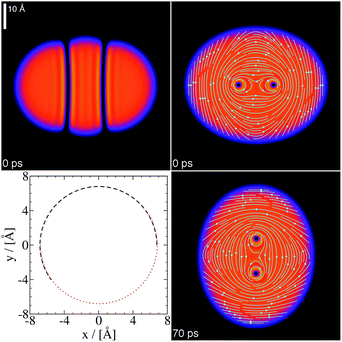 | ||
| Fig. 7 4He1000 droplet at ω = 0.0229 ps−1: Top panels, stationary two-vortex configuration in the x–z plane (left) and x–y plane (right) in the co-rotating frame. Bottom left panel, trajectory of the vortex cores in the x–y plane of the laboratory frame. The dashed line is the trajectory of one of the vortex cores, and the dotted line that of the other. Both trajectories overlap for a rigid rotation of the cores. Bottom right panel, helium density in the x–y plane at t = 70 ps obtained in the laboratory frame starting from the above configuration.39 | ||
At variance with the single vortex line along the symmetry axis of the droplet, the two-vortex configuration is not stationary in the laboratory frame, where the density and velocity field change with time. To show this, Ψ(r) has been evolved in the laboratory for about 150 ps taking as an initial condition the stationary configuration in the co-rotating frame. As expected, the vortex cores appear to rotate in the laboratory frame. Within the numerical accuracy, they do so rigidly. This can be seen in Fig. 7. Besides, they rotate precisely at ω = 0.0229 ps−1. This is a stringent test of the accuracy of the dynamics and the consistency of the method. It can be seen in the ESI† material how the two vortex lines turn around each other.
Fig. 7 shows how a superfluid droplet hosting a vortex array “rotates”. The fact that the vortex cores rotate rigidly is not in contradiction with the irrotational character of the superfluid flow, since they are empty. The cores carry along with them the superfluid whose velocity field is irrotational, whereas for a rigid solid or a classical liquid in steady flow one has v = ω × r, hence ∇ × v = 2ω. The circulation lines in Fig. 7 do not correspond to a rigid rotation, but to an irrotational flow in the presence of two vortices. The helium density adapts to the vortex cores as they rotate and this gives the appearance of a solid rotation in the laboratory frame, but it is not.
It is worth discussing the different configurations that may appear when ω < ωc. The lowest energy corresponds to the current-free (CF) 〈Lz〉 = 0 configuration. Metastable one-vortex (1V) configurations with 〈Lz〉 = Nħ also exist in this angular frequency range.42,44 Other irrotational (IR) configurations with 〈Lz〉 < Nħ do exist, arising from velocity potentials such as, e.g., ![[scr S, script letter S]](https://www.rsc.org/images/entities/char_e532.gif) (r) = αxy. For an ellipsoidal droplet with a sharp surface, the parameter α is related to the angular velocity around the z-axis and the deformation of the ellipsoid, see the Appendix and ref. 47–49.
(r) = αxy. For an ellipsoidal droplet with a sharp surface, the parameter α is related to the angular velocity around the z-axis and the deformation of the ellipsoid, see the Appendix and ref. 47–49.
These IR configurations may be generated by using the phase ![[scr S, script letter S]](https://www.rsc.org/images/entities/char_e532.gif) (r) = αxy in eqn (11) and minimizing 〈H − ω
(r) = αxy in eqn (11) and minimizing 〈H − ω![[L with combining circumflex]](https://www.rsc.org/images/entities/i_char_004c_0302.gif) z〉. At a given value of ω < ωc, the energies in the co-rotating frame are ordered as ECF < EIR < E1V. Fig. 8 shows the stationary configuration in the co-rotating frame corresponding to ω = 0.10 K/ħ = 0.0131 ps−1. Although this angular frequency is close to ωc, this configuration is hardly distorted and hosts a negligible amount of angular momentum: less than 5 × 10⁻²ħ, compared to the value of 103ħ at ωc. The circulation lines can be analytically calculated if the density profile is approximated by that of an ellipsoid with constant density, see the Appendix.
z〉. At a given value of ω < ωc, the energies in the co-rotating frame are ordered as ECF < EIR < E1V. Fig. 8 shows the stationary configuration in the co-rotating frame corresponding to ω = 0.10 K/ħ = 0.0131 ps−1. Although this angular frequency is close to ωc, this configuration is hardly distorted and hosts a negligible amount of angular momentum: less than 5 × 10⁻²ħ, compared to the value of 103ħ at ωc. The circulation lines can be analytically calculated if the density profile is approximated by that of an ellipsoid with constant density, see the Appendix.
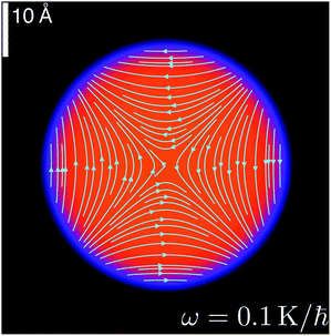 | ||
| Fig. 8 Stationary configuration of the 4He1000 droplet at ω = 0.10 K/ħ = 0.0131 ps−1 in the co-rotating frame (x–y plane). | ||
Figures similar to Fig. 8 are shown in ref. 47 and 48 for a rotating elliptic vessel filled with a fluid whose flow is irrotational. While in the case of a rigid solid or viscous liquid in steady flow the entire system rotates as a whole, an irrotationally flowing fluid in a rotating vessel is just pushed by the walls of the container; the same happens for a Bose–Einstein condensed gas in a rotating trap.49 For an isolated self-bound 4He droplet, the apparent “rotation” of the system in the laboratory arises from deformations of the fluid elements constituting the droplet, but not from their local rotation which is forbidden by the irrotational condition. The vorticity Ω [defined in hydrodynamics as50Ω = ∇ × v(r)], initially distributed in the helium droplet when it is in the normal phase, concentrates in the vortex lines when the droplet becomes superfluid and its velocity field becomes irrotational.
The above discussion shows how difficult it is to set a superfluid droplet in rotation. Experimentally,11–13 the situation is different, since the helium droplet is initially in a normal phase state at a temperature above the normal-to-superfluid transition temperature Tλ (about 2.17 K in bulk liquid at 1 bar). As a consequence, it may store large amounts of angular momentum and experience large deformations. Copious evaporation drives the droplet into a superfluid state at a temperature below Tλ and the angular momentum remaining in the droplet is then stored in vortex arrays that are being nucleated.
3.3 Dynamics of Xe and Ar capture by vortex lines
To study the interaction of an atomic impurity with vortices, we have imprinted a vortex line in the 4He1000 droplet and prepared the Xe atom under different kinematic conditions.The inelastic scattering of xenon atoms by quantized vortices in superfluid bulk helium has been addressed in ref. 32. It was found that a head-on collision leads to the capture of Xe by the vortex line at v0 = 15.4 m s−1, but not at v0 = 23.7 m s−1. We have carried out an equivalent simulation by initially placing the Xe atom inside the droplet 10 Å away from the vortex line and sending it head-on towards the vortex at a velocity of 10 m s−1. This velocity is of the order of the thermal velocity of a Xe atom in a droplet under experimental conditions, once the droplet has thermalized after capturing the Xe atom (T ∼ 0.4 K).4 Since the equilibrium position of the Xe atom is at the center of the droplet, it moves to this region and remains there during the rest of the simulation. In this region of the droplet, the Xe atom is also attracted by the vortex, but it is deflected by the superfluid flow around the vortex line and ends up orbiting around it. Hence, it is captured by the vortex without getting into its core.
A detailed analysis of the Xe capture as a function of the impact parameter has also been carried out in ref. 32, with the conclusion that when the impact parameter of the Xe atom approaching the vortex line is larger than about 5 Å, Xe is deflected but not captured.32 In the case of droplets, the final result is very different. Upon capture, the Xe atom wanders erratically inside the droplet, as we have seen in the case of vortex-free droplets. The surface of the droplet deforms dynamically and acts as a “pinball machine”, which eventually brings the Xe atom close enough to the vortex line if it missed it in the first attempt or was not previously ejected off the droplet.
The smoothest capture process one might think of corresponds to the Xe atom being initially placed at rest on the droplet surface, as no kinetic energy is given to the impurity. The Xe atom is accelerated towards the center of the droplet due to the attractive He–Xe interaction. We show that, under these kinematic conditions, some He atoms are first drawn towards the impurity because they are lighter, also see Fig. 9 and 10 in ref. 39. Eventually, the impurity with its “solvation structure” sinks, acquires some velocity, and is also deflected by the velocity field of the vortex line.
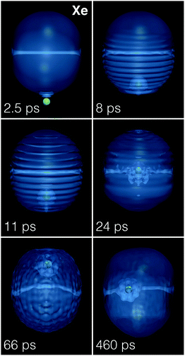 | ||
| Fig. 9 Dynamic evolution of a Xe atom (green dot) approaching a 4He1000 droplet hosting a vortex line from below at v0 = 200 m s−1. The corresponding time is indicated in each frame.39 | ||
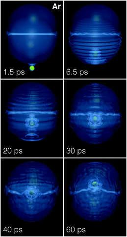 | ||
| Fig. 10 Dynamic evolution of an Ar atom (green dot) approaching a 4He1000 droplet hosting a vortex line from below at v0 = 360 m s−1. The corresponding time is indicated in each frame.39 | ||
We have tried two different initial locations of the Xe atom on the droplet surface. One is a point on the equator of the droplet, in a plane perpendicular to the vortex line; the other location is one of the open vortex core ends. Our aim was to see if a sensible difference in the transit time of Xe across the droplet could be detected. The simulations do not show important differences between the time taken by the impurity to reach the center of the droplet. It is about 20% larger when Xe starts from the equator than from the core end.39 It is worth noting that in the latter case the sliding of the impurity along the core proceeds rather smoothly, and that the impurity oscillates back and forth much as in the vortex-free case.
The simulation of Xe (v0 = 200 m s−1) and Ar (v0 = 360 m s−1) atoms head-on colliding with a 4He1000 droplet perpendicularly to the vortex line has been analyzed and compared with the results corresponding to a vortex-free droplet. The trajectory of the Xe and Ar atoms in phase space is shown Fig. 3. In both cases, the trajectory of the impurity is limited to the region of the droplet around the vortex line. The impurity orbits around the vortex line because the superfluid flow does so. Since in the DFT approach no dissipation is included, the signature of the capture of an impurity by a vortex is its close orbiting around the vortex line, as shown in the figure and especially in ref. 39. The ESI† material shows that while Ar is captured during its first transit across the droplet, the Xe atom is only captured in its second transit. We attribute this difference to the larger solvation energy of Xe (see Section 3.2), which requires more time to be dissipated. It can be seen39 that when Xe detaches from the vortex in the first transit, the vortex line is reconnected near the atomic solvation structure because no open ends can remain in the bulk of the droplet.
Fig. 9 and 10 show that when the impurity hits the droplet surface, a series of surface and volume density waves are launched. These waves travel much faster than the impurity itself, which has lost a large amount of kinetic energy when it pierced the surface.
The displacement of the atom in the droplet produces sound waves in the liquid and distortions along the vortex line (Kelvin modes). It is worth seeing that before bending by collision with the impurity, the vortex line is twisted (helical Kelvin mode). This is due to the interference between the spherical wave front flow produced by the hitting of the droplet surface, which travels from bottom to top, and the flow around the vortex core. The spherical wave front hits first the central portion of the vortex line, whose ends are anchored on the droplet surface. This yields the appearance of the helical distortion along the vortex line shown in Fig. 11. The twisting can no longer be followed after the impurity solvation structure reaches the vortex line, bending and dragging it along in the course of its orbiting around it. But it is clearly visible before as shown in Fig. 11, which displays the density of the droplet around the vortex line at the indicated collision time.
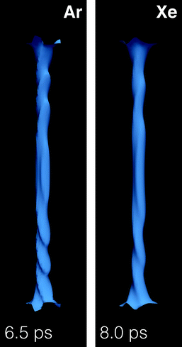 | ||
| Fig. 11 Core structure of the vortex line in a 4He1000 droplet after colliding with Xe at v0 = 200 m s−1 (right panel, t = 8 ps) and Ar at 360 m s−1 (left panel, t = 6.5 ps). The full structure of the droplet is shown in Fig. 9 and 10. | ||
We have thus shown that Xe and Ar atoms are readily captured by vortex lines in helium droplets under conditions prevailing in the experiments.11,12 Simulating the capture of a huge number of impurities or clusters by vortex arrays in very large droplets is beyond reach at present. However, the results presented in this subsection are the proof of concept that the limitation is technical and not conceptual.
3.4 Vortex arrays in 4He droplets doped with Ar atoms
The existence of ordered vortex lattices inside 4He droplets has been established by the appearance of Bragg patterns from Xe clusters trapped inside the vortex cores in droplets made of N = 108–1011 atoms (corresponding to radii from 100 to 1000 nm).11,12 We have recently studied the stability of vortex arrays made of up to nv = 9 vortices inside a 4He nanodroplet using the DFT approach.42 It was found that the energetically favored structure for nv > 6 is a ring of vortices encircling a vortex at the center of the droplet. For nv = 6, the configuration with a six-vortex ring is found to have almost the same energy as the five-fold ring plus a vortex at the center. The former structure has been experimentally observed,11–13 although classical vortex theory predicts for it a much higher free energy cost than for the latter.51 Similar equilibrium structures have been obtained within DFT for helium nanocylinders hosting vortex arrays.44In the experiments of ref. 12, the diffraction images show that rotating 4He nanodroplets of about 200 nm in diameter contain a small number of symmetrically arranged quantum vortices whose cores are filled with regularly spaced Xe clusters. Unexpected large distances of the vortices from the droplet center (∼0.7–0.8 droplet radii) are observed and explained as a result of the balance between the contribution of the Xe atoms to the total angular momentum of the droplets and the solvation potential of the embedded Xe atoms, which opposes the migration of vortices towards the droplet surface and their annihilation there, as it would happen instead in the case of undoped vortices at low values of the droplet rotational frequency.
In practice, as more and more Xe atoms become attached to a vortex, they adopt the angular velocity of its revolution about the droplet center. If the Xe capture is isotropic, the total angular momentum of the droplet is conserved, and thus the angular momentum accompanying the Xe rotational motion must be transferred from the vortices to the impurities. This reduction in the angular momentum of the vortices causes them to move outwards, resulting in the larger equilibrium distances of the vortices observed in the experiments. The actual equilibrium radial positions result from a balance between this tendency to move towards the droplet surface and the solvation potential, which tends instead to draw impurities towards the droplet center.
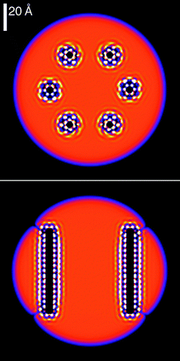
We have looked for stationary configurations of a 6-vortex ring in a rotating He15000 droplet by solving the EL equations in the co-rotating frame with a fixed angular velocity. Each vortex core is filled with Ar atoms, and the system is allowed to fully relax. In the end, the column of atoms inside each vortex core reaches an equilibrium structure where the Ar atoms are separated by a distance which is roughly that of the Ar dimer. One such configuration is shown in Fig. 12. Note that the vortex cores are almost straight lines, whereas in an undoped droplet rotating with the same velocity the vortex lines would be bent, as shown e.g. in Fig. 7. The Ar atoms are not shown in the figure. The localized structures appearing in the vortex cores are regions of highly inhomogeneous, high 4He density resulting from the Ar–He attractive potential.
The presence of impurities thus confers rigidity to the vortex lines, preventing them from bending. Yet, the small segment of the vortex line free from impurities bends so as to hit the droplet surface perpendicularly, see the bottom panel of Fig. 12. Note that in the absence of vortices, Ar atoms initially placed in a linear chain structure would relax towards the lower energy, compact configuration of an Ar cluster in the bulk of the droplet. However, once trapped by a vortex core, their collapse into such a cluster structure does not occur, i.e. an energy barrier appears and prevents the formation of Ar clusters. Our simplified description of the more complex experimental conditions (where each vortex line hosts chains of regularly spaced atomic clusters, instead of chains of single atoms) is due to computational limitations.
Our choice of Ar instead of Xe as a dopant is motivated by the weaker He–Ar and Ar–Ar interactions, which facilitate the imaginary-time relaxation. The interaction of the helium environment with several close-by impurities increases the strength of dopant–droplet interaction, producing helium localization around the impurities (snowball structures), see Fig. 9. Stabilizing these structures is extremely time consuming, especially when the He–impurity interaction is strong. Experiments were also carried out with Ar atoms as dopants, but have not been analyzed yet.52 However, no significant difference is expected between argon and xenon, neither from the experimental nor from the theoretical viewpoint.
There are obvious differences in scales between our simulations and the actual experiments, due to computational cost. In experiments, heavier impurities are used (Xe), the droplets are much larger and doping is known to occur by filling the vortex cores with a chain of equally spaced Xe clusters, each made of hundreds of atoms, instead of atom chains as done in our simulations. In spite of these differences, we find results which qualitatively explain the unusual behavior of vortex lines experimentally observed in doped rotating helium droplets.
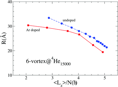
We have looked for the equilibrium structure of the Ar@6-vortex 4He15000 droplet for different imposed values of the angular velocity of rotation. The results show that doping inside each vortex core adds substantial stability to the system, such that doped vortices are still stable in a droplet rotating at rather low values of the angular velocities, whereas undoped vortices at such values would be pushed towards the surface of the droplet and eventually expelled. The solvation potential effect becomes apparent below some critical value of the angular velocity, where the vortices cease to move towards the surface and the system reaches an equilibrium maximum distance of the vortices from the droplet center. This is shown in Fig. 13, where we plot the radial distance of the vortices from the center as a function of the angular momentum of the system. Note how doped vortices are stable at values of the angular momentum well below the stability limit of an undoped droplet. A similar behavior has been observed in the experiment (see for instance Fig. 2 in the ESI† of ref. 12).
4 Summary and outlook
We have shown that Xe and Ar atoms at thermal velocities are readily captured by helium droplets, with a capture cross section similar to the geometric cross section of the droplet. Crucially for the subsequent capture of impurities by vortex lines, we have also shown that most of the kinetic energy of the impinging impurity is lost in the capture process during the first tens of picoseconds. This happens either by the ejection of prompt-emitted He atoms or by the production of sound waves and large deformations in the droplet.If the droplet hosts a vortex, slowly moving impurities are readily captured by the vortex line. Rather than being trapped inside the vortex core, the impurity is bound to move at a close distance around it. Besides the crucial energy loss when the impurity hits the droplet, the capture by the vortex is favored by a further energy transfer from the impurity to the droplet: large amplitude displacements of the vortex line – as shown in the ESI† accompanying this work – take place, constituting another source of the kinetic energy loss in the final stages of the capture. A related issue is the appearance of Kelvin modes in the vortex line, that is not only bent, but also twisted in the course of the collision.
If the kinematic conditions of the collision (kinetic energy and impact parameter) lead to the capture of the impurity by the droplet, the pinball effect caused by the droplet surface can induce the meeting of the Xe/Ar atom and the vortex line – and the possible capture of the atom by the vortex –, since both have a tendency to remain in the inner region of the droplet. We have shown this in the case of Xe at v0 = 200 m s−1: Xe is captured during its second transit across the droplet, whereas this could not have happened in bulk liquid helium.32
The capabilities of the He-DFT approach might help elucidate processes of experimental interest, such as the capture of one or several impurities by large droplets hosting a vortex array and how several atomic impurities, impinging upon a rotating droplet hosting vortices, react to form small clusters, eventually being trapped within the vortex cores as it appears in the experiments.
Appendix
In this Appendix, we discuss the relationship between the angular velocity and angular momentum of a deformed droplet below the critical angular frequency for vortex nucleation.Let us consider an ellipsoidal vessel filled with liquid 4He uniformly rotating around the z axis, ω = ω![[k with combining circumflex]](https://www.rsc.org/images/entities/b_char_006b_0302.gif) . The ellipsoid has the equation
. The ellipsoid has the equation
where
![[scr S, script letter S]](https://www.rsc.org/images/entities/char_e532.gif) is the velocity potential defined here so that
is the velocity potential defined here so thatIts existence is granted by irrotationality; we also have V = ω × r = ω(−y,x,0). A vector perpendicular to the ellipsoid surface is n = ∇F(x,y,z). From the stationarity condition (v′·n)|surf = 0, one obtains
It can be checked that
![[scr S, script letter S]](https://www.rsc.org/images/entities/char_e532.gif) = αxy is a solution to this equation provided that
= αxy is a solution to this equation provided thatHence,
and
The velocity in the laboratory is v = (ħ/m4)∇
![[scr S, script letter S]](https://www.rsc.org/images/entities/char_e532.gif) = (ħ/m4)α(y,x,0), and in the vessel (co-rotating frame) is v′ = β(R12y, − R22x,0), where β ≡ 2ω/(R12 + R22). Once they have been determined, their circulation lines are straightforwardly obtained. In the laboratory frame, they are
= (ħ/m4)α(y,x,0), and in the vessel (co-rotating frame) is v′ = β(R12y, − R22x,0), where β ≡ 2ω/(R12 + R22). Once they have been determined, their circulation lines are straightforwardly obtained. In the laboratory frame, they are| x2 − y2 = c, |
These lines are “parallel” to the ellipsoidal surface.
We define the deformation parameter ε
For the sharp surface ellipsoid above,
 | (16) |
if we write
| Ψ(r) = Φ(r)eιαxy |
If eqn (16) holds,
 | (17) |
is the irrotational moment of inertia. For a rigid solid,
Hence,
Finally, we discuss the kinetic energy of the droplet
From the above Ψ(r),
where the first term is the “intrinsic” kinetic energy and the second term arises from the irrotational velocity field
These expressions may be used to obtain some estimates from the actual DFT calculations. For a 4He1000 droplet and ω = 0.10 K/ħ, we have obtained 〈x2〉 = 100.82 Å2 and 〈y2〉 = 101.82 Å2; hence, ε ∼ −1/200. Since ħ2/m4 = 12.12 K Å2, from eqn (16) one has α ∼ −4.2 × 10⁻⁵ Å−2. From eqn (17), we obtain 〈Lz〉 ∼ 4 × 10⁻²ħ.
In a Bose–Einstein condensate, the deformation ε is a control parameter that can be set to a very large value (close to unity). For a self-bound 4He droplet, deformation comes from “rotation” itself and it turns out to be minute even for angular frequencies close to the critical frequency for one-vortex nucleation; the conclusion is that the droplet “does not rotate”; in other words, it is unable to store an appreciable amount of angular momentum before vortex nucleation.
Acknowledgements
We would like to thank Antonio Muñoz, Jordi Ortín, Humphrey Maris and Andrey Vilesov for useful discussions and exchanges. We would also like to thank Nicolas Renon and Emmanuel Courcelle of CALMIP who greatly improved the performance of our code. This work has been performed under Grant No. FIS2014-52285-C2-1-P from DGI, Spain, and 2014SGR401 from Generalitat de Catalunya. MB thanks the Université Fédérale Toulouse Midi-Pyrénées for financial support through the “Chaires d'Attractivité 2014” Programme IMDYNHE. The dynamic simulations presented in this work have been carried out thanks to the HPC resources of the CALMIP supercomputing center (Grant P1039).References
- A. Scheidemann, J. P. Toennies and J. A. Northby, Phys. Rev. Lett., 1990, 64, 1899 CrossRef CAS PubMed.
- F. Stienkemeier, J. Higgins, C. Callegari, S. I. Kanorsky, W. E. Ernst and G. Scoles, Z. Phys. D, 1996, 38, 253 CrossRef CAS; F. Ancilotto, P. B. Lerner and M. W. Cole, J. Low Temp. Phys., 1995, 101, 1123 CrossRef.
- A. Hernando, R. Mayol, M. Pi, M. Barranco, F. Ancilotto, O. Bünermann and F. Stienkemeier, J. Phys. Chem. A, 2007, 111, 7303 CrossRef CAS PubMed.
- J. P. Toennies and A. F. Vilesov, Angew. Chem. Phys., 2004, 43, 2622 CrossRef CAS.
- F. Stienkemeier and K. K. Lehmann, J. Phys. B: At., Mol. Opt. Phys., 2006, 39, R127 CrossRef CAS.
- J. Tiggesbäumker and F. Stienkemeier, Phys. Chem. Chem. Phys., 2007, 9, 4748 RSC.
- C. Callegari and W. E. Ernst, Handbook of High Resolution Spectroscopy, Wiley, New York, 2011, vol. 3, p. 1551 Search PubMed.
- M. Mudrich and F. Stienkemeier, Int. Rev. Phys. Chem., 2014, 33, 301 CrossRef CAS.
- M. Lewerenz, B. Schilling and J. P. Toennies, J. Chem. Phys., 1995, 102, 8191 CrossRef CAS.
- L. F. Gomez, E. Loginov, R. Sliter and A. Vilesov, J. Chem. Phys., 2011, 135, 154201 CrossRef PubMed.
- L. F. Gomez, K. R. Ferguson, J. P. Cryan, C. Bacellar, R. Mayro P. Tanyag, C. Jones, S. Schorb, D. Anielski, A. Belkacem, C. Bernando, R. Boll, J. Bozek, S. Carron, G. Chen, T. Delmas, L. Englert, S. W. Epp, B. Erk. L. Foucar, R. Hartmann, A. Hexemer, M. Huth, J. Kwok, S. R. Leone, J. H. S. Ma, F. R. N. C. Maia, E. Malmerberg, S. Marchesini, D. M. Neumark, B. Poon, J. Prell, D. Rolles, B. Rudek, A. Rudenko, M. Seifrid, K. R. Siefermann, F. P. Sturm, M. Swiggers, J. Ullrich, F. Weise, P. Zwart, C. Bostedt, O. Gessner and A. F. Vilesov, Science, 2014, 345, 906 CrossRef CAS PubMed.
- C. F. Jones, Ch. Bernando, R. Tanyag, K. R. Ferguson, C. Bacellar, L. Gomez, D. Anielski, A. Belkacem, R. Boll, J. Bozek, S. Carron, J. Cryan, L. Englert, S. W. Epp, B. Erk, R. Hartmann, L. Foucar, D. M. Neumark, D. Rolles, B. Rudek, A. Rudenko, K. R. Siefermann, F. P. Sturm, J. Ullrich, F. Weise, Ch. Bostedt, O. Gessner and A. F. Vilesov, Phys. Rev. B, 2016, 93, 180510(R) CrossRef.
- C. Bernando, R. Mayro, P. Tanyag, C. Jones, C. Bacellar, M. Bucher, K. R. Ferguson, D. Rupp, M. P. Ziemkiewicz, L. F. Gomez, A. S. Chatterley, T. Gorkhover, M. Müller, J. Bozek, S. Carron, J. Kwok, S. L. Butler, T. Möller, Ch. Bostedt, O. Gessner and A. F. Vilesov, Phys. Rev. B, 2017, 95, 064510 CrossRef.
- R. M. P. Tanyag, C. F. Jones, C. Bernando, S. M. O. O'Connell, D. Verma and A. F. Vilesov, Experiments with large superfluid helium nanodroplets, in Cold Chemistry: Molecular Scattering and Reactivity Near Absolute Zero, ed. A. Osterwalder and O. Dulieu, Royal Society of Chemistry, Cambridge, UK, to be published, ch. 8, 2017 Search PubMed.
- V. Lebedev, P. Moroshkin, B. Grobety, E. B. Gordon and A. Weis, J. Low Temp. Phys., 2011, 165, 166 CrossRef CAS.
- L. F. Gomez, E. Loginov and A. F. Vilesov, Phys. Rev. Lett., 2012, 108, 155302 CrossRef PubMed.
- E. Latimer, D. Spence, C. Feng, A. Boatwright, A. M. Ellis and S. Yang, Nano Lett., 2014, 14, 2902 CrossRef CAS PubMed.
- Ph. Thaler, A. Volk, F. Lackner, J. Steurer, D. Knez, W. Grogger, F. Hofer and W. E. Ernst, Phys. Rev. B: Condens. Matter Mater. Phys., 2014, 90, 155442 CrossRef.
- G. P. Bewley, S. Matthew, S. Paoletti, R. Katepalli, R. Sreenivasan and D. P. Lathrop, Proc. Natl. Acad. Sci. U. S. A., 2008, 105, 13707 CrossRef CAS PubMed.
- A. Leal, D. Mateo, A. Hernando, M. Pi and M. Barranco, Phys. Chem. Chem. Phys., 2014, 16, 23206 RSC.
- A. Vilà, M. González and R. Mayol, Phys. Chem. Chem. Phys., 2016, 18, 2006 RSC.
- A. Hernando, M. Barranco, M. Pi, E. Loginov, M. Langlet and M. Drabbels, Phys. Chem. Chem. Phys., 2012, 14, 3996 RSC.
- F. Coppens, A. Leal, M. Barranco, N. Halberstadt and M. Pi, J. Low Temp. Phys., 2017, 187, 439 CrossRef CAS.
- Microscopic approaches to quantum liquids in confined geometries, Series on Advances in Quantum Many-Body Theory, ed. E. Krotscheck and J. Navarro, World Scientific, Singapore, vol. 4, 2002 Search PubMed.
- M. Barranco, R. Guardiola, S. Hernández, R. Mayol, J. Navarro and M. Pi, J. Low Temp. Phys., 2006, 142, 1 CrossRef CAS.
- J. von Vangerow, A. Stieg, F. Stienkemeier, M. Mudrich, A. Leal, D. Mateo, A. Hernando, M. Barranco and M. Pi, J. Phys. Chem. A, 2014, 118, 6604 CrossRef CAS PubMed.
- D. Mateo, A. Leal, A. Hernando, M. Barranco, M. Pi, F. Cargnoni, M. Mella, X. Zhang and M. Drabbels, J. Chem. Phys., 2014, 140, 131101 Search PubMed.
- A. Leal, D. Mateo, A. Hernando, M. Pi, M. Barranco, A. Ponti, F. Cargnoni and M. Drabbels, Phys. Rev. B: Condens. Matter Mater. Phys., 2014, 90, 224518 CrossRef.
- A. Leal, X. Zhang, M. Barranco, F. Cargnoni, A. Hernando, D. Mateo, M. Mella, M. Drabbels and M. Pi, J. Chem. Phys., 2016, 144, 094302 Search PubMed.
- J. von Vangerow, F. Coppens, A. Leal, M. Pi, M. Barranco, N. Halberstadt, F. Stienkemeier and M. Mudrich, J. Phys. Chem. Lett., 2017, 8, 307 CrossRef CAS PubMed.
- F. Ancilotto, M. Barranco, F. Caupin, R. Mayol and M. Pi, Phys. Rev. B: Condens. Matter Mater. Phys., 2005, 72, 214522 CrossRef.
- I. A. Pshenichnyuk and N. G. Berloff, Phys. Rev. B, 2016, 94, 184505 CrossRef.
- D. Kivotides, C. F. Barenghi and Y. A. Sergeev, Phys. Rev. B: Condens. Matter Mater. Phys., 2008, 77, 014527 CrossRef.
- K. T. Tang and J. P. Toennies, Z. Phys. D, 1986, 1, 91 CrossRef CAS.
- M. Frigo and S. G. Johnson, Proc. IEEE, 2005, 93, 216 CrossRef.
- A. Ralston and H. S. Wilf, Mathematical methods for digital computers, John Wiley and Sons, New York, 1960 Search PubMed.
- D. Mateo, D. Jin, M. Barranco and M. Pi, J. Chem. Phys., 2011, 134, 044507 CrossRef PubMed.
- 4He-DFT BCN-TLS: A Computer Package for Simulating Structural Properties and Dynamics of Doped Liquid Helium-4 Systems. M. Pi, F. Ancilotto, F. Coppens, N. Halberstadt, A. Hernando, A. Leal, D. Mateo, R. Mayol and M. Barranco, http://https://github.com/bcntls2016/.
- See the ESI† for the continuous movie corresponding to the simulation.
- D. L. Whitaker, M. A. Weilert, C. L. Vicente, H. J. Maris and G. M. Seidel, J. Low Temp. Phys., 1998, 110, 173 CrossRef CAS.
- M. Pi, R. Mayol, A. Hernando, M. Barranco and F. Ancilotto, J. Chem. Phys., 2007, 126, 244502 CrossRef PubMed.
- F. Ancilotto, M. Pi and M. Barranco, Phys. Rev. B: Condens. Matter Mater. Phys., 2015, 91, 100503(R) CrossRef.
- F. Dalfovo, R. Mayol, M. Pi and M. Barranco, Phys. Rev. Lett., 2000, 85, 1028 CrossRef CAS PubMed.
- F. Ancilotto, M. Pi and M. Barranco, Phys. Rev. B: Condens. Matter Mater. Phys., 2014, 90, 174512 CrossRef.
- W. F. Vinen, Proc. - R. Soc. Edinburgh, Sect. A: Math. Phys. Sci., 1961, 260, 218 CrossRef CAS.
- G. A. Williams and R. E. Packard, Phys. Rev. Lett., 1974, 33, 280 CrossRef CAS.
- G. M. Seidel and H. J. Maris, Physica B, 1994, 194–196, 577 CrossRef CAS.
- A. Bohr and B. R. Mottelson, Nuclear Structure, W. A. Benjamin, vol. II, App. 6A, 1975 Search PubMed.
- A. Recati, F. Zambelli and S. Stringari, Phys. Rev. Lett., 2001, 86, 377 CrossRef CAS PubMed.
- E. Guyon, J.-P. Hulin, L. Petit and C. D. Mitescu, Physical Hydrodynamics, Oxford University Press, Oxford, UK, 2nd edn, 2015 Search PubMed.
- L. J. Campbell and R. M. Ziff, Phys. Rev. B: Condens. Matter Mater. Phys., 1979, 20, 1886 CrossRef CAS.
- A. F. Vilesov, Private communication, 2017.
Footnote |
| † Electronic supplementary information (ESI) available. See DOI: 10.1039/c7cp03307a |
| This journal is © the Owner Societies 2017 |


