 Open Access Article
Creative Commons Attribution 3.0 Unported Licence
Supramolecular porphyrin-based metal–organic frameworks: Cu(II) naphthoate–Cu(II) tetrapyridyl porphine structures exhibiting selective CO2/N2 separation†
Tetsushi
Ohmura
 *a,
Norihiko
Setoyama
a,
Yusuke
Mukae
a,
Arimitsu
Usuki
a,
Shunsuke
Senda
b,
Tsuyoshi
Matsumoto
c and
Kazuyuki
Tatsumi
b
aToyota Central R&D Labs., Inc., 41-1, Yokomichi, Nagakute, Aichi 480-1192, Japan. E-mail: e1314@mosk.tytlabs.co.jp
bResearch Center for Materials Science, Nagoya University, Furo-cho, Chikusa-ku, Nagoya, Aichi 464-8602, Japan
cInstitute of Transformative Bio-Molecules (WPI-ITbM), Nagoya University, Furo-cho, Chikusa-ku, Nagoya, Aichi 464-8601, Japan
First published on 1st August 2017
Abstract
1 and 2 were synthesized through the complexation of 5,10,15,20-tetra-4-pyridyl-21H,23H-porphine with copper(II) acetate and copper(II) 1-naphthoate and exhibited two-dimensional open and closed form structures, respectively. X-ray diffraction identified the supramolecular interactions leading to these packing motifs. N2 and CO2 sorption isotherms indicate that 2 allows the separation of these gases.
Introduction
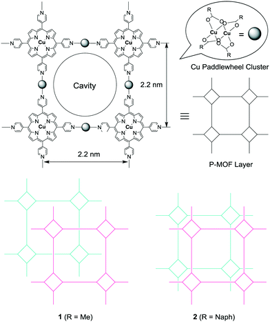
Porphyrin-based metal–organic frameworks (P-MOFs) incorporating cavities have been widely studied in recent years. These compounds take advantage of the ability to accurately control the configuration of active sites, with anticipated applications in gas storage and catalysis, based on various combinations of transition metals and substituted organic ligands.1 Further, advanced functional materials based on porphyrin assemblies have also been extensively studied.2 One of the most versatile components for the construction of P-MOFs is 5,10,15,20-tetra-4-pyridyl-21H,23H-porphine (H2TPyP). The tetragonal orientation of the peripheral pyridine ligands allows the formation of infinite parallel sheets with lattice structures in which four pyridyl groups are linked together by transition metal ions.3Recently, we reported an example of a porous P-MOF comprised of H2TPyP in a four-connected vertex with Cu paddlewheel clusters as linear linker motifs, forming regular 2 or 3-D coordination networks with an open format.3d As shown in Scheme 1, the H2TPyP units are tetragonally connected via the Cu paddlewheel clusters in an infinite 2-D sheet structure with a 2.2 nm-wide square grid structure. Some P-MOFs exhibit very interesting properties that suggest potential applications, such as the selective sorption of gas molecules to modify CO2 concentrations.1d,4 We have therefore developed a strategy in which H2TPyP and paddlewheel linkers are used to construct P-MOFs, increasing the potential for these materials to act as adsorbents exhibiting selectivity for CO2/N2. In this communication, we report the syntheses and characterizations of these P-MOFs.
Experimental
Complexes 1 and 2 and CuNaph were synthesized and the products were confirmed by single-crystal X-ray diffraction (XRD). H2TPyP was purchased from Aldrich, while copper(II) acetate (Cu(OAc)2), 1-naphthoic acid (Naph), and the solvents (special grade) were purchased from Wako. The single crystal required for XRD analysis was prepared using a diffusion technique at room temperature. To synthesize 1, a solution of Cu(OAc)2 dissolved in methanol was carefully layered on top of a solution of H2TPyP dissolved in chloroform. The resultant mixture was allowed to stand for 1–2 weeks, during which time reddish-brown crystals of the Cu(OAc)2–CuTPyP (1) were formed. To obtain 2, a solution of copper(II) 1-naphthoate (CuNaph) dissolved in ethanol was carefully layered onto a solution of H2TPyP dissolved in chloroform. The resultant mixture was allowed to stand for 1–2 weeks, during which time dark-brown crystals of the CuNaph–CuTPyP (2) were formed. CuNaph was synthesized by layering a solution of Cu(OAc)2 dissolved in methanol over top of a solution of Naph dissolved in ethyl acetate. The resultant mixture was allowed to stand for 1–2 weeks, during which time emerald green crystals of CuNaph were formed. Single-crystal XRD structural data were collected for 1, 2, and CuNaph. In preparation for these analyses, the crystals were first coated with a light hydrocarbon oil and then mounted on a loop in the nitrogen stream of the diffractometer. Diffraction data for the complexes were obtained under a cold N2 stream using a Rigaku AFC8 equipped with a Saturn70 CCD detector for 1, a Rigaku FR-E equipped with a Pilatus 200 K detector for 2, and a Rigaku UltraX18 equipped with a Mercury CCD detector for CuNaph, employing graphite-monochromated Mo Kα radiation. The structure of 1 was solved by direct methods (SIR2014)5 with the Crystal Structure crystallographic software package and refined by full-matrix least-squares procedures on F2. The structure of 2 was solved by direct methods (SHELXL2013)6 with the Crystal Structure crystallographic software package and refined by full-matrix least-squares procedures on F2. The structure of CuNaph was solved by direct methods (SIR92)7 with the Crystal Structure crystallographic software package and refined by full-matrix least-squares procedures on F. The SADI command was applied when modeling the disordered benzene rings of the 1-naphthoate moieties in 2. The 1-naphthoate benzene rings in 2 were modelled as rigid groups using the EADP command. Non-hydrogen atoms were refined anisotropically, while hydrogen atoms were refined using the rigid model. In the case of 1 and 2, the contribution of the solvent electron density was removed using the SQUEEZE routine in PLATON.8 The final structures were validated using the PLATON cif check feature. The crystal data and structural refinement details are provided below and in the ESI.† Crystal data for 1: tetragonal, I4/mmm (#139), a = b = 22.3460(7), c = 14.2977(7) Å, V = 7139.5(5) Å3, 2θMax = 55.1°, Z = 16 and R1 = 0.0486. Crystal data for 2: monoclinic, P21/c (#14), a = 17.653(4), b = 43.763(11), c = 18.317(5) Å, β = 102.967(3)°, V = 13![[thin space (1/6-em)]](https://www.rsc.org/images/entities/char_2009.gif) 790(6) Å3, 2θMax = 55.1°, Z = 4 and R1 = 0.0987. Crystal data for CuNaph: monoclinic, P21/n (#14), a = 13.918(5), b = 8.908(3), c = 17.689(7) Å, β = 94.416(7)°, V = 2186.5(14) Å3, 2θMax = 54.9°, Z = 2 and R1 = 0.0429.
790(6) Å3, 2θMax = 55.1°, Z = 4 and R1 = 0.0987. Crystal data for CuNaph: monoclinic, P21/n (#14), a = 13.918(5), b = 8.908(3), c = 17.689(7) Å, β = 94.416(7)°, V = 2186.5(14) Å3, 2θMax = 54.9°, Z = 2 and R1 = 0.0429.
Results and discussion
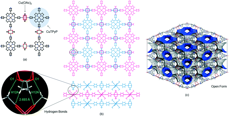
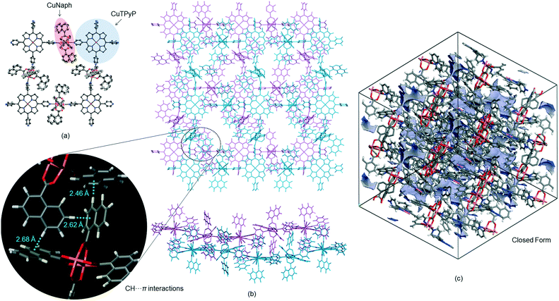
The reaction of H2TPyP and Cu(OAc)2 produced reddish-brown crystals of 1 with a 2-D lattice structure (Fig. 1a). The 2-D sheets were interconnected through hydrogen bonds (2.693 Å) between H atoms on the methyl groups of one 2-D sheet and O atoms on the carboxylate moieties of an adjacent 2-D sheet (Fig. 1b). This value is shorter than the hydrogen bonds (2.828–2.954 Å) in [MeC(O)N(H)PEt3]2[Cu2(O2C–Me)4Cl2].9 Because the 2-D sheets in 1 do not interpenetrate, the channels that run through the structure can be used for gas absorption following evacuation of the P-MOF (Fig. 1c).3d In contrast, a combination of H2TPyP and CuNaph generated brown crystals of 2, also having a 2-D lattice structure (Fig. 2a). The CuNaph was synthesized from Cu(OAc)2 and Naph, producing green crystals consisting of molecules having paddlewheel structures, using a procedure similar to that described in the literature.10 Here, the 2-D sheets were interconnected through CH⋯π interactions (2.46–2.68 Å) between 1-naphthoate groups on the faces and edges of adjacent 2-D sheets (Fig. 2b). These value are shorter than the CH⋯π interactions (2.83–2.99 Å) in [Cu2(O2CC14H9)4(CH3OH)2].10 Although the 2-D sheets in 2 do not interpenetrate, the channels in this material cannot be used for gas absorption because the pores are blocked by bulky 1-naphthoate ligands (Fig. 2c).CHCl3 solvent molecules initially filled the lattice cavities in 1. The void fraction in the structure, estimated from the free volume to cell volume ratio after CHCl3 was released from the open form structure using the van der Waals surface method,11 was remarkably high at 0.67. This calculation assumes that the structure of the MOF skeleton did not change upon solvent removal due to the stabilizing effect of the hydrogen bonds between the 2-D sheets. The crystalline form of 2, despite the closed form, was found to have a relatively small void fraction of 0.27.
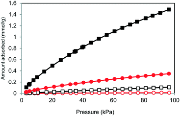
The BET surface areas obtained for 1 and 2 from N2 adsorption measurements at −196 °C were 812 and 1 m2 g−1, respectively, which correspond to essentially open and closed structural forms. However, 2 unexpectedly exhibited CO2 adsorption at 0 °C. To examine selective CO2 capture by 1 and 2, CO2 and N2 sorption isotherms were acquired up to 100 kPa at 0 °C (Fig. 3). The isotherms for both at 0 °C demonstrate no uptake in the low concentration region but slowly increasing adsorption at higher concentrations. The materials were not saturated under these conditions, and the amount of CO2 adsorbed by 2 was 0.349 mmol g−1 (15.3 mg g−1), which was lower than the 1.49 mmol g−1 (65.5 mg g−1) determined for 1. However, the selectivity for CO2/N2 obtained from 2 was far superior to that of 1 (2: 49.6, 1: 22.9). Here, the selectivity under adsorption conditions was calculated using the equation α12ads = (N1ads/N2ads)(y2/y1) described in the literature.4e,12 The value obtained for 2 is comparable to those reported for various MOFs and zeolites.4
 | ||
| Fig. 3 CO2 and N2 adsorption isotherms for 1 and 2 at 0 °C (black squares, CO2 for 1; open squares, N2 for 1; red circles, CO2 for 2; open circles, N2 for 2). | ||
The closed-open transition is a vital aspect of the gas adsorption of these materials because the trigger for the transformation of the interaction between the host and guest determines the degree of selectivity. The observation that 2 adsorbs CO2 but not N2 shows that the selectivity results from the quadrupole moment or polarizability of the guest molecules, since both factors greatly affect the dispersion force of the guest.13
Conclusions
We report 2-D P-MOFs constructed from Cu-based paddlewheel clusters and CuTPyP. Applications of these novel P-MOFs include the selective sorption of gas molecules. This study demonstrates that both P-MOFs and, in particular, compound 2 is a suitable candidate for selectivity for CO2/N2. We believe that this selective adsorption property can also be used for catalytic reaction. Furthermore, by using the limited reaction field of MOF, high selectivity can be expected. Further studies of catalytic activity for the conversion of CO2 into useful chemicals are now in progress.Acknowledgements
The synchrotron radiation experiments were performed on the BL22XU beamline at the SPring-8 facility with the approval of the Japan Synchrotron Radiation Research Institure (JASRI). The authors wish to thank Dr. Akihiko Machida for assistance with the experiments at Spring-8, Mr. Masami Yamamoto (Toyota Central R&D Laboratories, Inc.) for performing TD-MS analyses of 2, and Mr. Yoshinori Idota (Toyota Central R&D Laboratories, Inc.) for performing the CO2 adsorption measurements of 2.Notes and references
- (a) S. Matsunaga, N. Endo and W. Mori, Eur. J. Inorg. Chem., 2011, 4550 CrossRef CAS; (b) T. R. Cook, Y.-R. Zheng and P. J. Stang, Chem. Rev., 2013, 113, 734 CrossRef CAS PubMed , and references therein; (c) Q. Zha, C. Ding, X. Rui and Y. Xie, Cryst. Growth Des., 2013, 13, 4583 CrossRef CAS; (d) W.-Y. Gao, M. Chrzanowski and S. Ma, Chem. Soc. Rev., 2014, 43, 5841 RSC , and references therein; (e) Q. Zha, X. Rui, T. Wei and Y. Xie, CrystEngComm, 2014, 16, 7371 RSC , and references therein; (f) X. Rui, Q.-Z. Zha, T.-T. Wei and Y.-S. Xie, Inorg. Chem. Commun., 2014, 48, 111 CrossRef CAS; (g) S. Matsunaga, N. Endo and W. Mori, Chem. Lett., 2017, 46, 937 CrossRef CAS.
- (a) P. Guo, P. Chen and M. Liu, ACS Appl. Mater. Interfaces, 2013, 5, 5336 CrossRef CAS PubMed; (b) P. Guo, G. Zhao, P. Chen, B. Lei, L. Jiang, H. Zhang, W. Hu and M. Liu, ACS Nano, 2014, 8, 3402 CrossRef CAS PubMed; (c) C. Zhang, P. Chen, H. Dong, Y. Zhen, M. Liu and W. Hu, Adv. Mater., 2015, 27, 5379 CrossRef CAS PubMed; (d) G. Geng, P. Chen, B. Guan, L. Jiang, Z. Xu, D. Di, Z. Tu, W. Hao, Y. Yi, C. Chen, M. Liu and W. Hu, ACS Nano, 2017, 11, 4866 CrossRef CAS PubMed.
- (a) C. V. K. Sharma, G. A. Broker, J. G. Huddleston, J. W. Baldwin, R. M. Metzger and R. D. Rogers, J. Am. Chem. Soc., 1999, 121, 1137 CrossRef CAS; (b) L. Carlucci, G. Ciani, D. M. Proserpio and F. Porta, Angew. Chem., Int. Ed., 2003, 42, 317 CrossRef CAS PubMed; (c) L. Carlucci, G. Ciani, D. M. Proserpio and F. Porta, CrystEngComm, 2005, 7, 78 RSC; (d) T. Ohmura, A. Usuki, K. Fukumori, T. Ohta, M. Ito and K. Tatsumi, Inorg. Chem., 2006, 45, 7988 CrossRef CAS PubMed; (e) L. D. DeVries and W. Choe, J. Chem. Crystallogr., 2009, 39, 229 CrossRef CAS , and references therein; (f) R. W. Seidel and I. M. Oppel, Struct. Chem., 2009, 20, 121 CrossRef CAS; (g) R. W. Seidel and I. M. Oppel, CrystEngComm, 2010, 12, 1051 RSC; (h) R. W. Seidel and I. M. Oppel, Z. Anorg. Allg. Chem., 2010, 636, 446 CrossRef CAS; (i) M.-H. Xie, X.-L. Yang, C. Zou and C.-D. Wu, Inorg. Chem., 2011, 50, 5318 CrossRef CAS PubMed.
- (a) R. V. Siriwardane, M.-S. Shen, E. P. Fisher and J. A. Poston, Energy Fuels, 2001, 15, 279 CrossRef CAS; (b) B. Wang, A. P. Côté, H. Furukawa, M. O'Keeffe and O. M. Yaghi, Nature, 2008, 453, 207 CrossRef CAS PubMed; (c) S. R. Miller, P. A. Wright, T. Devic, C. Serre, G. Férey, P. L. Llewellyn, R. Denoyel, L. Gaberova and Y. Filinchuk, Langmuir, 2009, 25, 3618 CrossRef CAS PubMed; (d) D. M. D'Alessandro, B. Smit and J. R. Long, Angew. Chem., Int. Ed., 2010, 49, 6058 CrossRef PubMed; (e) Y.-S. Bae and R. Q. Snurr, Angew. Chem., Int. Ed., 2011, 50, 11586 CrossRef CAS PubMed; (f) S. Yang, X. Lin, W. Lewis, M. Suyetin, E. Bichoutskaia, J. E. Parker, C. C. Tang, D. R. Allan, P. J. Rizkallah, P. Hubberstey, N. R. Champness, K. M. Thomas, A. J. Blake and M. Schröder, Nat. Mater., 2012, 11, 710 CrossRef CAS PubMed; (g) T. Bataille, S. Bracco, A. Comotti, F. Costantino, A. Guerri, A. Ienco and F. Marmottini, CrystEngComm, 2012, 14, 7170 RSC; (h) G. E. Cmarik, M. Kim, S. M. Cohen and K. S. Walton, Langmuir, 2012, 28, 15606 CrossRef CAS PubMed; (i) T.-H. Bae, M. R. Hudson, J. A. Mason, W. L. Queen, J. J. Dutton, K. Sumida, K. J. Micklash, S. S. Kaye, C. M. Brown and J. R. Long, Energy Environ. Sci., 2013, 6, 128 RSC.
- M. C. Burla, R. Caliandro, B. Carrozzini, G. L. Cascarano, C. Cuocci, C. Giacovazzo, M. Mallamo, A. Mazzone and G. Polidori, J. Appl. Crystallogr., 2015, 48, 306 CrossRef CAS.
- G. M. Sheldrick, Acta Crystallogr., Sect. A: Found. Crystallogr., 2008, 64, 112 CrossRef CAS PubMed.
- A. Altomare, G. Cascarano, C. Giacovazzo, A. Guagliardi, M. C. Burla, G. Polidori and M. Camalli, J. Appl. Crystallogr., 1994, 27, 435 Search PubMed.
- A. L. Spek, J. Appl. Crystallogr., 2003, 36, 7 CrossRef CAS.
- H. Ackermann, B. Neumüller and K. Dehnicke, Z. Anorg. Allg. Chem., 2000, 626, 1712 CrossRef CAS.
- M. Kyuzou, A. Maeda, M. Wada, S. Watanabe, T. Takei, T. Ohmura, Y. Kowaguchi, W. Mori and J. Tanaka, Bull. Chem. Soc. Jpn., 2011, 84, 491 CrossRef CAS.
- (a) D. Sun, F. S. Tham, C. A. Reed and P. D. W. Boyd, Proc. Natl. Acad. Sci. U. S. A., 2002, 99, 5088 CrossRef CAS PubMed; (b) T. Ohmura, A. Usuki, Y. Mukae, H. Motegi, S. Kajiya, M. Yamamoto, S. Senda, T. Matsumoto and K. Tatsumi, Chem. – Asian J., 2016, 11, 700 CrossRef CAS PubMed.
- N is the adsorbed amount and y is the molar fraction in the gas phase. Subscripts 1 and 2 indicate the strongly adsorbed component (CO2) and the weakly adsorbed component (N2), respectively. The ads superscripts mean adsorption conditions.
- S. Shimomura, M. Higuchi, R. Matsuda, K. Yoneda, Y. Hijikata, Y. Kubota, Y. Mita, J. Kim, M. Takata and S. Kitagawa, Nat. Chem., 2010, 2, 633 CrossRef CAS PubMed.
Footnote |
| † Electronic supplementary information (ESI) available: Single-crystal X-ray diffraction (XRD), thermal desorption mass spectrometry (TD-MS), and synchrotron powder XRD (PXRD) data. The CCDC numbers for the as-synthesized 1, 2 and CuNaph are 1556754, 1556756 and 1556755. For ESI and crystallographic data in CIF or other electronic format see DOI: 10.1039/c7ce01138e |
| This journal is © The Royal Society of Chemistry 2017 |


