Smart supercapacitors with deformable and healable functions
Kai
Guo
,
Neng
Yu
,
Zhiqiang
Hou
,
Lintong
Hu
,
Ying
Ma
,
Huiqiao
Li
* and
Tianyou
Zhai
*
State Key Laboratory of Material Processing and Die & Mould Technology, School of Materials Science and Engineering, Huazhong University of Science and Technology, Wuhan 430074, P. R. China. E-mail: hqli@hust.edu.cn; zhaity@hust.edu.cn
First published on 10th November 2016
Abstract
Rapid development of wearable electronic devices stimulates the demand for matched energy storage devices. Such a complex application requires electronic devices and their power units to possess mechanically deformable ability and even healing capability to accommodate large scale mechanical deformation and self-heal cracks or fractures. Supercapacitors (SCs) are regarded as promising power units for wearable electronic devices due to the advantages of high power density, rapid charge rate, ultra-long life, great stability and safety. But conventional rigid SCs or primarily flexible SCs (bendable or twistable) are far from the requirements of practical applications of wearable electronic devices. SMART SCs with intensively deformable or healable abilities have been developed to satisfy these rigorous demands and have become a hot topic recently. In this article, we introduce the recent progress in this booming research area of compressible, self-healable, and shape memory SCs. For each type of these SMART SCs, the device or electrode structure design, the functional materials and their working mechanism, and the employed electrolyte are discussed in detail. Moreover, we also outline the challenges and perspective for the development of advanced SMART SCs. Both the mechanical and electrochemical performance of the SMART SCs require improvement. Meanwhile, it will be a fascinating trend to integrate multiple mechanical and non-mechanical functions into SMART SCs to make them novel self-powered multi-functional units in the near future.
1. Introduction
The rapid development of wearable electronic devices not only enriches our daily lives, but also challenges us in the pursuit of matched power units or devices at the same time.1–4 Because of such a complex application, wearable electronic devices usually need to be integrated into non-planar substrates with complex shapes or confined to a limited space, so they are probably deformed: bent, twisted, stretched or compressed, statically or dynamically.5,6 Consequently the electronic devices and their power units can inevitably short-circuit under large compression, and be fractured by accumulated or excessive strains, or injured by cutting. Moreover, replacing the power units in a highly integrated electronic device may be impossible or both expensive and time-consuming. Thus, durable power units with various deformable functions and maintenance-free are urgently demanded.Supercapacitors (SCs) are promising energy storage devices to power wearable electronic devices because of their outstanding features, such as high power density, rapid charge rate, ultra-long life, easy maintenance, great stability and safety compared with lithium ion batteries.7–11 However, conventional SCs are rigid with a planar or cylinder shape (Fig. 1) and can hardly fulfil the critical flexibility of wearable electronic devices In order to gain flexibility, primary flexible SCs based on flexible substrates or self-standing films that can be bent to different curvatures or twisted (Fig. 1) have been developed in the past decade.12–15 But simple bendability or twist ability is far from meeting the actual requirements of stretchability or compressibility, which are necessary for wearable devices.
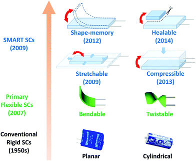 | ||
| Fig. 1 The development history of SCs: conventional rigid SCs, such as the commercial Maxwell® planar and cylindrical electrochemical double-layer SCs. The first patent about electrochemical double-layer SCs appears in the 1950s. Then, the first flexible SCs (bendable and twistable) appeared in a research paper in 2007.25 The report of mechanically SMART SCs, including stretchable, compressible, healable and shape-memory SCs appears in 2009, 2013, 2014 and 2012, respectively. | ||
The appearance of advanced SCs with stretchable and compressible functions paves the way for practical applications of SCs in wearable devices. Early stretchable SCs based on a pre-stressed stretchable substrate can merely be stretched up to tens of percent of their initial sizes and in only one direction. Recently, stretchable SCs have to be extended to hundreds of percent of the initial scale and in any direction.16–18 As a reverse of the tensile force, the pressure is also inevitable in practical applications for wearable devices. Research results indicate that the pressure can obviously affect the microstructure and electrochemical performance of SCs and large compression can lead to short-circuit of SCs.19,20 It is of fundamental importance and practical necessity to study the compression effect on the SCs for performance optimization and structure design. Therefore, compressible SCs with high compression tolerant ability are supposed to be important power devices and have aroused a lot of interest.21–23
Excessive strains or cuts will cause invisible cracks or even fracture of the SC devices, which also leads to the failure of electrochemical functions of SCs. A healable SC that can repair itself and restore its function automatically or with an external stimulus is an ideal solution. The healing ability will be an indispensable function of SCs and also other wearable electronic devices, such as electrically conducting wires,24 electric skin26 and sensors.27 In addition, the accumulation of deformations (e.g. bending, twisting and stretching) over time during the service life of wearable SCs can lead to structural fatigue and fracture in SCs and will cause degradation of their performance or even malfunction. Shape-memory materials which can recover the initial shape have been applied in various devices and have potential for reducing the accumulated strain.28,29 Shape-memory SCs based on shape-memory materials with the capability of recovering from plastic deformations are supposed to avoid the accumulation of deformations and extend the lifetime of SCs.30 The combination of shape-memory materials and SCs will stimulate many new applications.
Stretchable, compressible, shape-memory and healable SCs are much more resistant to the deformation or fracture than primary flexible SCs, hence they are named as SMART SCs in this review. The SMART SCs integrating deformable and healable functions are a booming research area and attract more and more attention. In this review, we introduce the recent progress in SMART SCs. A brief introduction to stretchable SCs is first given. Then the development of compressible, healable and shape-memory SCs is discussed, especially focusing on the device or electrode structure design, functional materials and their working mechanism, and the employed electrolyte. Finally, the challenges and opportunities for SMART SCs are also discussed. Both the mechanical and electrochemical performance of the SMART SCs require improvement. At the same time, the integration of multi mechanical and non-mechanical functions into SMART SCs will be a fascinating research trend.
2. Stretchable SCs
In practical applications, SCs inevitably encounter stretching and elongation of devices. The elongation can be uniaxial, biaxial or omnidirectional. In order to accommodate the deformation and make SCs stretchable, some novel strategies have been developed to design stretchable electrodes or devices for SCs in the past several years, such as the wave structure, textile structure and interconnect-island structure.The wave-structured stretchable SC electrodes are assembled by attaching conductive and capacitive films on pre-strained polymer substrates and releasing. Two stretchable electrodes are separated by an electrolyte soaked separator or gel electrolyte to fabricate a stretchable SC. This wave structural configuration can accommodate large tensile strains by changing the wave amplitudes and wavelengths to avoid the fracture of the capacitive films, and has become one of the most successful strategies for stretchable SCs.31 Based on the wave configuration, highly stretchable electrodes with a stretchability of >140% were realized, and the SCs made with the electrodes showed a stable electrochemical performance even up to 120% strain.16 In addition, it is facile to fabricate SCs which can be stretched biaxially32,33 or omnidirectionally17,34 by modifying the pre-strain shapes of the polymer substrates.
Another effective strategy to fabricate stretchable SCs is based on the textile structural configuration. The stretchable electrodes were synthesized by coating conductive and capacitive materials on the fabric textiles, such as single wall carbon nanotubes (SWCNTs) or conducting polymer polypyrrole (PPy).35,36 The SCs based on the textile structure can be reversibly stretched to a strain of 100–120%.
The stretchable SCs based on the interconnect-island configuration were assembled by patterning rigid SC arrays on or into a stretchable polymer substrate. And the isolated SCs were connected with stretchable metal strips.37 The resulting SCs demonstrated stable electrochemical performance up to 100% uniaxial and 50% biaxial stretching. A similar stretchable micro SC array was realized by designing a honeycomb device structure and the SC can be stretched up to 275%.38
Other than the paper-like stretchable SCs, the recently emerged fibre-shaped stretchable SCs have attracted more and more attention. The fiber-shaped SCs are typically fabricated with elastic backbones, which are integrated as the backbones of non-elastic fibre-shaped SCs or cores of coaxial electrodes. The fibre-shaped stretchable SCs demonstrated a maximum stretchability of 100% and 350% for the former and latter strategies, respectively.18,39–41 Special substrate-free configurations for fibre-shaped stretchable SCs were also developed with spring-like or coiled carbon nanotube (CNT) yarn.42,43 Actually, the fiber-shaped stretchable SCs can be readily woven into omnidirectionally stretchable fabrics, rendering more convenience for applications.18,44
The stretchability of SCs can be improved by optimizing the device configuration. In order to improve the specific capacitance of the stretchable SCs, pseudocapacitive materials were introduced to form composites with carbon materials,41,45 and more and more research has been focused on the asymmetric SCs to enhance the energy densities recently.39,46–48
More information on the materials and performances of stretchable SCs has already been summarized by Yan and Xie et al.49,50 Thus, we provide a brief introduction to the stretchable SCs here.
3. Compressible SCs
Highly compressible SCs can remain electrochemically stable under large compressive deformation and recover their initial shape upon unloading. The whole device should be elastic to avoid structural collapse under compression and maintain a stable interface between the electrode and electrolyte to output a stable power. The compressibility of a SC arises from at least one of its components, the self-standing electrode, substrate or electrolyte. The device structure design, compressible materials and the electrolyte are especially of concern.3.1 The design strategy of compressible SCs
According to the compressible component and configuration, there are three types of structure design strategies for compressible SCs. (1) Compressible electrode structure, in which two compressible electrodes are separated by a separator, as shown in Fig. 2a.51 The compressible electrode can be self-standing or made by coating active materials on a compressible substrate. In this type of SC, the compression ability comes from the compressible electrodes. (2) All-in-one structure. In the all-in-one structure SC, the positive electrode, separator and negative electrode are coated on only one compressible foam-like substrate successively to form an interdigitated layer-by-layer film structure within 5 steps, as shown in Fig. 2b.22 (3) Compressible electrolyte based structure. A compressible electrolyte film, as shown in Fig. 2c, is sandwiched with two common electrodes to form a compressible SC (Fig. 2d).52 This gel electrolyte acts as the compressible component, the separator and the electrolyte at the same time.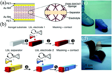 | ||
| Fig. 2 (a) Schematic of a solid-state SC constructed with two compressible sponge@SWCNT@PANI electrodes, a filter paper between electrodes as the separator, PVA/H2SO4 gel electrolyte, and two PET/Au flakes as current collectors.51 Copyright 2015, Wiley-VCH. (b) Schematic fabrication process of the all in one structured compressible SC through layer-by-layer infiltration of electrodes and separator dispersion in a porous aerogel substrate.22 Copyright 2015, Nature Publishing Group. (c) Demo of a compressible EMIMCl hydrogel electrolyte, and (d) a photograph of a symmetric compressible SC constructed with two carbon electrodes sandwiching the EMIMCl hydrogel film.52 Copyright 2014, Wiley-VCH. | ||
Among the above mentioned three types of compressible SCs, the electrolyte-based type is the most facile structure, since most gels are elastic and compressible, the common electrodes without special compressible design can be used in this system. However, the thickness of the compressible electrolyte film must be restricted within several millimeters to obtain a low ionic diffusion impedance. Thus, the compression scale is mostly limited to several millimeters in a compressible electrolyte type SC. On the contrary, the compression scale of an all-in-one structure SC is dependent on the compressible foam-like substrate and can reach one centimeter or more. And with all components integrated into one foam, the device can get rid of possible displacement of components during compression. But the assembly process of the device is relatively complex. And the inactive substrate would reduce the specific capacitance of the whole device to a large degree. The compressible electrode based type is a straight thought with advantages of both a facile assembly process and a large compression scale (centimeter scale). Thus it is the most frequently used structure in compressible SCs now. The development details of compressible electrodes are further discussed in the next section.
3.2 Compressible electrodes for compressible SCs
Compressible electrodes are the critical components in compressible electrode structured SCs, and high mechanical strength, porosity, good conductivity and large capacitance are required. Their structures are usually in the form of foam or sponge and can be divided into two types: substrate-based and self-standing electrodes.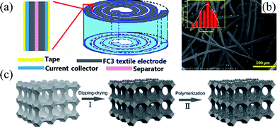 | ||
| Fig. 3 (a) A compressible SC made of carbon felt and spirally wound, and (b) the microstructure of the carbon fiber felt.53 Copyright 2015, Royal Society of Chemistry. (c) Schematic fabrication process of the sponge based compressible electrode fabricated by dip-coating SWCNTs and polymerization of PANI.51 Copyright 2015, Wiley-VCH. | ||
A compressible SC electrode can also be fabricated by simply coating a compressible foam with conductive SWCNT and polyaniline (PANI) capacitive layers, as shown in Fig. 3c.51 Solid-state SCs assembled with the symmetric hybrid sponge@SWCNT@PANI electrode demonstrated only 3% capacitance loss when the device was compressed to 60% Strain, and 13% loss in the capacitance was observed at a compression strain of 70%. Furthermore, the capacitance remained stable even up to 1000 compression release cycles. In addition to excellent compressibility, the synthesis of compressible sponge@SWCNT electrodes is on a large scale and of low cost. However, the non-active sponge substrate occupies a tremendous ratio of weight and volume in the SC electrode and device, and unavoidably limits both the gravimetric and volumetric capacitance of SCs.
Self-standing graphene aerogel foams have high porosity, good conductivity, and can be compressed. However, conventionally solution processed graphene aerogels easily collapse under compression because the two dimensional graphene sheets tend to stack together and lose surface area due to strong inter-sheet van der Waals interactions.54–56 The unstable structure upon compression hinders their applications as compression-tolerant electrodes in SCs. Recent results show that graphene foams can be elastic through modifications such as adjusting the microstructure of graphene sheets, compositing with other materials, or being cross-linked.57–62 For example, a biomimetic cellular structured graphene aerogel (Fig. 4a) can sustain structural integrity under a load of more than 5000 times of its own weight and can rapidly recover from more than 80% compression (Fig. 4b). After 1000 compression–release cycle of 80% strain, this graphene aerogel only experienced 7% reduction in thickness and retained more than 76% of maximum compression stress.57 The significant elasticity was attributed to the special microstructure, which is also found in a closed-cell cellular macroporous structured graphene foam.58
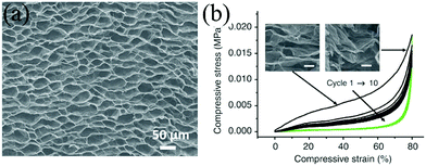 | ||
| Fig. 4 (a) SEM of graphene with a cellular structure and (b) its 10 cycles of stress–strain curves with a maximum compressive strain of 80%.57 Copyright 2012, Nature Publishing Group. | ||
Graphene nanoribbons (GNRs) uniformly attached or embedded within the graphene aerogel walls through π–π interactions can greatly reinforce the strength of graphene aerogels.61 The composite aerogel showed a max strain of 80% and recovered 97% of strain, while the graphene oxide (GO) aerogel recovered only 50% of the strain. After 1000 compression–release cycles at a strain of 50%, the GO–GNR aerogel retained the maximum stress with only 10% plastic deformation. Similarly, the PPy layer adhering on the surface of the graphene aerogel also remarkably enhanced the elasticity by avoiding the stacking of GO nanosheets during hydrothermal reactions, thinning out the wall and enlarging the pore size of the GO aerogel.59 The PPy loading also enhanced the specific capacitance of the graphene aerogel at the same time. PPy nanotubes were also introduced into rGO aerogels to prevent self-stacking of graphene, and enhance the compressibility and capacitance.60
Besides tuning the microstructure or introducing reinforced materials through physical interactions, Hong et al. developed a novel molecular scale modification method by covalently cross-linking polyvinyl alcohol (PVA) with rGO to enhance the elasticity of graphene foam.62 Under a compression strain of 60%, the stress for the composite x-rGO aerogel was 8.6 times greater than that of the bare rGO aerogel. Both macroscopic cracking and microscopic fracturing were observed for the rGO aerogel sheets, while the x-rGO aerogel remained with an almost unchanged microstructure, as shown in Fig. 5a. The existence of PVA was believed to play multifunctional roles in enhancing the elasticity. First, the functional groups of PVA facilitate good dispersion and full exfoliation of the rGO nanosheets. As a result, the thickness of the walls between pores is reduced in the hybrid aerogel. Second, the PVA is covalently cross-linked with GO (Fig. 5b), this is helpful in transferring the applied stresses to the covalently interconnected structures as shown in the schematic explanation of Fig. 5c.
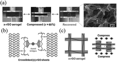 | ||
| Fig. 5 (a) The rGO sheets cross-linked with PVA (x-rGO) completely recovers from the compression test of 60% strain, without microscopic fracture. (b) Schematic cross-linking of PVA and rGO sheets and (c) the schematic mechanical load transfer process under compression.62 Copyright 2015, Wiley-VCH. | ||
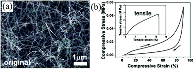 | ||
| Fig. 6 (a) SEM of CVD synthesized CNT sponge in its original (uncompressed) state and (d) its compressive stress–strain curves with a maximum compressive strain of 90%.63 Copyright 2013, Royal Society of Chemistry. | ||
Pseudocapacitive materials (such as metal oxides and conducting polymers) can be introduced into the CNT aerogel to enhance the capacitance without sacrificing the mechanical compressibility. Cheng et al. reported a three-dimensional porous CNT@α-Fe2O3 sponge, which showed an enhanced specific capacitance of 296.3 F g−1, remarkably higher than bare CNT sponge (80.2 F g−1).68 The mechanical and electrochemical performance of the CNT aerogel can be enhanced at the same time by coating with conducting polymers. Li et al. coated the CVD synthesized CNT sponge with conducting polymer PPy uniformly, as shown in Fig. 7a.67 The inter-contact joints of the CNT are welded by PPy (Fig. 7b), which could prevent slippage of CNTs during deformation. Mechanical testing shows that CNT@PPy composite sponges are more rigid and resistant to compression than bare CNT sponges, as presented in Fig. 7c. The specific capacitance of CNT@PPy is nearly not altered after 1000 compression cycles (Fig. 7d). Coating MnO2 on the surface of the PPy layer can further increase the capacitance of the sponge.69
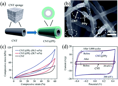 | ||
| Fig. 7 (a) Schematic of CNT@PPy synthesized through absorbing pyrrole and following electrochemical deposition. (b) The SEM image of CNT@PPy. (c) Compression testing results of the CNT and CNT@Ppy sponge. The composite sponge shows enhanced strength compared with the CNT sponge. (d) The cyclic voltammetry curves of CNT (scan rate of 20 mV s−1) and CNT@PPy sponges (scan rate of 200 mV s−1) before and after 1000 compression–release cycles show nearly no changes, and the CNT@PPy sponge demonstrates much larger current density compared with CNT sponge.67 Copyright 2013, Springer. | ||
In summary, most compressible electrodes are fabricated from self-standing carbon material foams or carbon material coated compressible substrates. The substrate-based electrodes have advantages of simple fabrication, large-scale production and good compressibility. Although the self-standing electrodes are complex in fabrication and have difficulty in maintaining reversible compressibility, their capacitance is absolutely higher than the substrate-based electrodes due to the absence of an inactive substrate. Besides the above-mentioned compressible electrodes, nitrogen-doped carbon fiber foams were fabricated by using one-step annealing industrial melamine foams. The compressible SCs based on carbon foam electrodes could be reversibly compressed under a max strain of 80% and endure 1000 compression cycles without obvious capacitance degradation. Inspired by this work, many other polymer foams may also be potential precursors for compressible carbon foams with large-scale production and low cost. The electrochemical performance under uncompressed and compressed states and the mechanical compression testing results of reported compressible electrodes are summarized in Table 1.
| Electrode | Electrolyte | Max capacitancea | Max compressive strain | Compression–release cycle | Ref. | ||
|---|---|---|---|---|---|---|---|
| Uncompressed | Compressed (strain) | Strain & cycles | Capacitance retention | ||||
| a The letter F in the brackets refers to the capacitance obtained with symmetric full cells, otherwise the capacitance is obtained with a 3-electrode system. | |||||||
| CNT@G | 1 M Na2SO4 | 100 F g−1 (F), 1 F cm−3 (F) | 100 F g−1 (F), 18 F cm−3 (F) (90%) | 90% | 60%, 2000 | 66 | |
| CNT (CVD) | 2 M KCl | 1.12 F g−1, 36 mF cm−3 | 0.8 F g−1, 128 mF cm−3 (80%) | 90% | 50%, 1000 | 96.4% | 63 |
| CNT@Fe2O3 | 2 M KCl | 296.3 F g−1 | 266.7 F g−1 (70%) | 70% | 50%, 1000 | 100% | 68 |
| CNT@PPy | 2 M KCl | 376 F g−1 (F) | >338.4 F g−1 (F) (50%) | 60% | 50%, 1000 | 98% | 67 |
| CNT/Graphene/PPy | 2 M KCl | 225 F g−1 | 206.1 F g−1 (50%) | 50% | 70 | ||
| CNT@PPy@MnO2 | 2 M KCl | 305.9 F g−1, 96 F cm−3 | 275.3 F g−1, 16.1 F cm−3 (50%) | 50% | 69 | ||
| Ppy-graphene | 3 M NaClO4 | 350 F g−1, 14 F cm−3 | 350 F g−1, 28 F cm−3 (50%) | 80% | 50%, 1000 | 100% | 59 |
| GO/GNR | 2 M KCl | 256 F g−1 | 80% | 50%, 1000 | 61 | ||
| x-rGO (PVA crosslinked rGO) | 1 M H2SO4 | 295 F g−1, 90 F g−1 (F), 0.94 F cm−3 (F) | 130 F g−1 (F), 13.6 F cm−3 (F) (90%) | 90% | 50%, 1000 | 100% | 62 |
| GO/PPy nanotubes | 1 M H2SO4 | 253 F g−1 | 70% | 60 | |||
| Sponge/SWCNTs/PANI | H2SO4/PVA | 216 F g−1 (F), 3.4 F cm−3 (F) | 187.9 F g−1 (F) (70%) | 70% | 60%, 200 | 100% | 51 |
| 3D cellulose nanofibril aerogel/CNT | 1 M Na2SO4 | 25 F g−1 | 75% | 75%, 400 | 100% | 22 | |
| Carbon nanofibril foam | 5 M LiCl | 332 mF cm−2, 52 F g−1 | 80% | 55%, 1000 | 100% | 21 | |
| Carbon nanofibril foam | LiCl/PVA | 132 F cm−3 (F), 10.3 F g−1 (F) | 60% | 21 | |||
3.3 Electrolytes for compressible SCs
In a previous study, the electrochemical performances of compressible SCs were observed in liquid electrolytes.63 Liquid electrolytes can easily impregnate to the porous foam electrodes and help exploiting the performance of compressible electrodes. However, the compression/release process of a SC is always accompanied with the absorption and desorption of liquid electrolytes, which increases the leakage risk. The utilization of a large amount of excessive electrolytes would decrease the total capacitance of the device. Besides, the gravimetric specific capacitance often degrades under compression, due to the reduced effective surface area by the contact of neighboring active materials in compression.21 Recently, gel electrolytes have been applied in compressible SCs.21,51 Fresh gel electrolytes can easily infiltrate and wet the porous framework of a compressible electrode. During compression–release, there is no leakage of electrolytes. Thus, packaging is not necessary with the gel electrolyte. In addition, the gel electrolyte can serve as a separator and avoid contact of neighboring parts in the electrode.21 As a result, the specific capacitance can remain stable even when the device was compressed with a large strain of 60%.514. Self-healable SCs
Wearable electronic devices are susceptible to structure fracture or cutting in practical applications, resulting in breakdown of whole devices, time consumption, being expensive, and electronic waste. By integration of self-healing ability into electronic devices and their power sources such as SCs, the electronic devices can recover their mechanical integrity and also electronic functions automatically or with the aid of external pressure or other short-time stimulus. As a result, the lifetime and durability of the electronic devices can be greatly increased and the maintenance cost can also be largely reduced. Actually, the self-healing of SCs includes two critical aspects: healing of mechanical integrity and healing of electric conductivity. The self-healing polymers serving as substrates, coating shells or electrolytes is the base of healable mechanical integrity, while the healing of conductivity is based on the recovery of mechanical integrity.4.1 Healing of mechanical integrity
In order to obtain recoverable self-healing capability, reversible healing polymers are required. Self-healing polymers can be classified into non-autonomous and autonomous systems which depend on whether an external stimulus is required. External triggers are required for non-autonomous self-healing polymers such as light, temperature and pH, whereas no triggers are needed for autonomous self-healing polymers.72,73 Self-healing polymers can also be divided into extrinsic and intrinsic strategies.26,72 Extrinsic self-healing polymers are embedded with encapsulated external healing agents which are released to initiate the self-repairing process of the polymers in case the polymers are damaged. Extrinsic self-healing can only occur once at one point, whereas the intrinsic self-healing polymers can heal itself at one point for many times. The intrinsic self-healing polymers repair themselves by highly reversible crosslinks, such as dynamic covalent chemical bonds and physical bonds. Self-healing polymers have been applied in various self-healing devices, such as lithium ion batteries,74,75 sensors76,77 and conductors.78,79The most commonly used self-healing polymers in SCs are based on reversible hydrogen bonding interactions, such as a self-healing polymer fabricated by a modified Leibler's method and carboxylated polyurethane (PU).80,81 For example, the tension strength of self-healing wires (synthesized with modified Leibler's method) was recovered to be typically about 79.1 and 72.5% after self-healing for one and five cycles. Flower-like TiO2 nanoparticles were introduced into the polymer to serve as additional hydrogen bond acceptors and donors. Consequently, the tensile strength and glass transition temperature were both increased.82 With more TiO2, the tensile strength became larger and the glass transition temperature was higher. After being cut, the composite was restored by a gentle pressure at a healing temperature of 50 °C for 5 min. This strategy is also very effective in the polyacrylic acid (PAA) hydrogel.71 Vinyl hybrid silica nanoparticles (VSNPs) were introduced into polyacrylic acid (PAA) and covalent crosslinks with the PAA chains were formed, as shown in Fig. 8a. The synergistic effects of covalent crosslinking and hydrogen bonding endowed the composite polymer with a highly efficient self-healing effect and great mechanical strength.
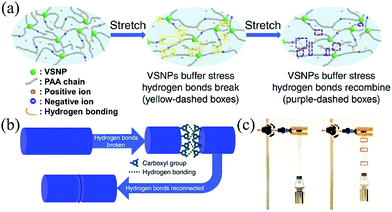 | ||
| Fig. 8 (a) Schematic of the origin of the super stretchability in the VSNP–PAA electrolyte. (b) Schematic of self-healing arising from interfacial hydrogen bonding in the electrolyte. (c) Demonstration of the self-healed electrolyte.71 Copyright 2015, Nature Publishing Group. | ||
With the VSNP–PAA hydrogel as a sample, the healing process of the polymer is as follows. When breakage occurs in the contact region of the polymer, plenty of broken hydrogen bonds expose on the surface of the fracture. Within a short time after the fracture, pressing the fresh fracture surfaces together can reconnect through the reconstruction of the hydrogen bonds at the broken interface of the PAA polymer main chains, leading to healing of the polymer as illustrated in Fig. 8b. After a polymer belt is healed, the belt can still be extensively stretched without breaking (Fig. 8c), indicating good efficiency of mechanical healing. Besides, gentle pressing, a little water or elevated temperature can effectively enhance the mechanical healing effect.80–82
4.2 Healing of conductivity
Typically, a conducting layer is coated on the surface of the self-healable polymer substrate and the process of conductivity healing is illustrated in Fig. 9a.82 When the broken parts are pressed together, the broken conducting layers contact and reconnect. The healing of conductivity determines the restoration efficiency of the electrochemical performance. However, it is very difficult to exactly align and ensure good reconnection of the broken electrodes, which is proved by increased resistance after healing. Different conducting materials affect the conductivity healing efficiency. Sun et al. compared the healing efficiency of aligned CNT sheet, silver nanowires and random CNT networks.80 The Ag nanowire based conducting layer had lowest resistance, and the highest resistance belonged to the CNT network. The resistance changed a lot after first healing with an increase of 8.5, 191.6 and 176.5% for aligned CNT sheet, Ag nanowire networks and CNT networks, respectively. The results indicated that the aligned CNT possessed the best healing efficiency.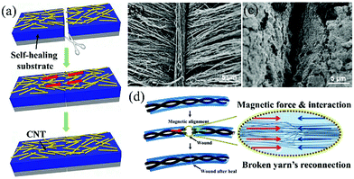 | ||
| Fig. 9 (a) Schematic self-healing process of the CNT film based electrode.82 Copyright 2014, Wiley-VCH. (b) A CNT automatically forms above the wound of the aligned CNT sheet after healing. (c) The wound of the CNT network sheet after healing.80 Copyright 2014, Wiley-VCH. (d) Schematic of the magnetic force assistant self-healing process of a fiber SC.81 Copyright 2015, American Chemistry Society. | ||
CNT films were also utilized in other reported studies for self-healing electrodes.71,80,82 The reason may be the one-dimensional morphology, intrinsic excellent conductivity, flexibility and the strong van der Waals force between CNTs. The nano-sized one-dimensional morphology increases the contact area of CNTs across the fracture and the strong attraction force between the CNTs can help reconnect the broken CNT film during the self-healing process. It needs to be mentioned that Sun's work also reveals that the distribution of CNTs (aligned and random) impact the healing efficiency of conductivity largely.80 There are some differences between randomly distributed CNTs and aligned CNT sheets. First, the aligned CNT sheet possesses higher conductivity because of the unobstructed conducting path between aligned CNTs. Second, a CNT strand could automatically be formed above the wound of the aligned CNT sheet, which is not present in the CNT network, as presented in Fig. 9b and c. This CNT strand is supposed to be critical in restoration of the conductivity of the CNT sheet. The reconnection of the conducting film is still not good with CNTs, because of the misalignment of the CNT sheet with visual inspection. In order to improve the conductivity healing efficiency, additional patches were applied over the wound, which remarkably enhanced the self-healing efficiency of conductivity.71 Although the tensile strength degraded with cut-healing times, the healing efficiency of electrochemical performance was ∼100% during all 20 breaking/healing cycles, which is the best result so far, suggesting the very high healing efficiency of conductivity. However, this patch assistant method could not be easily realized in a packaged device.
Other than carbon materials, metal fibers have also been used in fiber-shaped SCs as current collectors because they are highly conductive and flexible. After fracture, the metal fibers cannot reconnect or be healable by themselves like the healable polymers. A novel strategy was developed to reconnect broken metal based electrodes by introducing an external force, as illustrated in Fig. 9d.81 A stainless yarn, comprising of a bundle of microfibers, was deposited with a magnetic Fe3O4 layer, and then became magnetic. When the broken yarns were pushed together, the large number of microfibers made more chances for the microfibers across the two broken parts to contact each other. The attractive magnetic force further aligned the microfibers and made their contact tightly, resulting in good conductivity healing efficiency.
In conclusion, the healing of integrity is premise of the healing of conductivity, but the latter is more difficult for SCs, because of two main reasons. Firstly, the sizes of electrodes and self-healing components (substrates, shells or electrolytes) are different. The thickness of electrodes is typically restricted to less than 100 μm because the specific capacitance decreases quickly with thickness.80,83 It is difficult to precisely align the broken thin electrode layer with visual inspection especially when the electrodes are covered by self-healing substrates or shells. On the contrary, the self-healing components are often with a thickness71,82 or diameter80,81 of several hundred micrometers to millimeters in order to make sure good mechanical strength of SCs after being healed. Thus, it is easier for self-healing components to align with a larger size. Secondly, the intrinsic properties of electrode materials and self-healing polymers are different. The self-healing components are adhering because of reversible interactions inside, such as hydrogen bonds. For electrode materials, there are usually van der Waals interactions which are relatively weak compared with hydrogen bonds.71,80 So, an external force or patch is usually required for better conductivity healing efficiency.
4.3 Electrolytes for self-healing SCs
The leakage of liquid electrolytes is inevitable when the self-healing SC is damaged, which radically excludes the application of liquid electrolytes in self-healing SCs. Solid electrolytes can provide highly mobile ions without a liquid and can also serve as separators in the self-healing SCs. Among various solid electrolytes, glasses, crystals and ceramics are not a good choice for self-healing SCs, because they are rigid and against the trend of flexible electronics. On the contrary, gel electrolytes are soft, adhering, and can infiltrate into the electrodes to increase the contact area with active materials before solidification. Thus, gel electrolytes are the best choice for self-healing SCs. Gel electrolytes comprising polymer frameworks and solvated salts can be divided into hydrogels, organic gels and ionic liquid gels according to the solvents.84 Hydrogel electrolytes are the most common electrolytes for self-healing SCs because of high ionic conductivity (10−4 to 10−3 S cm−1), mechanical strength, good stability, low cost and toxicity. For example, PVP–H2SO4 hydrogels,82 PVA–H2SO4 hydrogels80 and PVA–H3PO4 hydrogels81 were coated on the surface of electrodes as both the electrolyte and separator of self-healing SCs. Gel electrolytes can be self-healed by using a self-healing polymer or introducing a self-healing agent. A novel hydrogen bonds and vinyl hybrid silica nanoparticles dual cross-linked polyacrylic acid electrolyte was synthesized by Huang et al.71 This electrolyte possesses a high self-healability, stretchability and tunable ionic conductivity. It can self-heal the wound at room temperature and recover most of its original ionic conductivity after multiple breaking/healing cycles. Even when being stretched to 3700%, no cracks were observed in the electrolyte.4.4 Self-healing SCs
So far, paper-like and fiber-shaped self-healing SCs have been reported. Due to the different device dimensions, the structures for paper-like and fiber-shaped self-healing SCs should be discussed separately. The device structure of paper-like self-healing SCs is divided into self-healing substrate based structure (Fig. 10a)82 and self-healing gel electrolyte based structure (Fig. 10b),71 according to different self-healing components.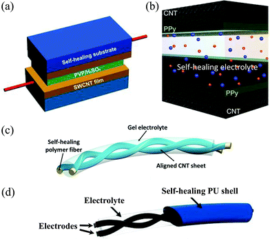 | ||
| Fig. 10 (a) Schematic device configuration of a paper-like healable SC with self-healing substrates covering a supercapacitor. The supercapacitor is assembled with two SWCNT films sandwiching a gel electrolyte (PVP/H2SO4).82 Copyright 2014, Wiley-VCH. (b) Schematic device configuration of a healable SC fabricated with gel electrolyte and CNT@PPy film electrodes.71 Copyright 2015, Nature Publishing Group. (c) Schematic of a fiber-shaped SC based on self-healing polymer cores80 (Copyright 2014, Wiley-VCH) or (d) a self-healing polymer shell81 (Copyright 2015, American Chemistry Society). | ||
In the substrate based structure, self-healing materials are attached to the electrodes as substrates, and do not participate in electrochemical reactions. They can also serve in packaging of SCs.82 The acid-treated SWCNT film was spread on the surface of the healable polymer/TiO2 nanoparticle composite film to form a healable conducting electrode. A solid-state SC was constructed with two such electrodes sandwiching a PVA/H2SO4 gel film, showing a capacitance of 35 F g−1 at 1 A g−1. After the first, third and fifth healing, the SC maintained a capacitance of 34, 32 and 30 F g−1 respectively, indicating a high efficient restoration of capacitance. The degradation of capacitance was along with increasing equivalent series resistance respect to cut-healing times, indicating the partly reconnected CNT film at the fracture.
Huang et al. reported an electrolyte based structure healable SC, which was constructed by sandwiching a special VSNP–PAA gel electrolyte (as described in the above part) with two PPy coated CNT films.71 The calculated capacitance with this VSNPs–PAA electrolyte was comparable or even higher than some results tested in a liquid electrolyte, and completely overlaid those values using PVA based gel electrolytes. In order to overcome the well-known misalignment of electrodes in self-healable devices, small patches of CNT paper were applied on the cutting wounds of the SC to assist the restoration of conductivity. Compared with the substrate based structure, there is no need for inactive healable substrates, so the total mass and volume of the self-healing SC can be reduced.
Fiber shaped self-healing SCs that can be woven into fabrics with advanced fatigue-resistant properties are promising for practical applications, especially in wearable electronic devices. There are also two typical structures for fiber shaped self-healable SCs based on the position of the self-healing polymer: the self-healing core (Fig. 10c)80 and the self-healing shell (Fig. 10d).81 For the former structure, self-healing polymers serve as the core of conducting fiber electrodes, and two fiber electrodes are twisted to construct a self-healing SC. Peng et al. developed a self-healing wire-shaped SC based on twisted conducting wire-shaped electrodes, which were made of aligned CNT sheets wrapping on a self-healing polymer wire.80 The SC demonstrated a maximum capacitance of 11.1 F g−1, and maintained 82.6% of capacitance after fifth cutting/healing cycle. After introducing a second active phase PANI, the specific capacitance reached 140 F g−1 (1.34 mF cm−1) and recovered to 92% after self-healing.
The shell based SC was constructed by encapsulating a fiber-shaped SC with a self-healing polymer shell.81 A stainless steel yarn consisting of a bunch of microfibers was coated with magnetic Fe3O4 nanoparticles successively. Polyurethane (PU) was selected as the outmost layer of the SC because it is self-healable, mechanically strong and compatible with the textile industry. The tensile strength of the device after healing arose from the PU shell. After fourth healing, the specific capacitance retained 71.8% with great maintenance of the whole device's mechanical strength. This work inspires the design and fabrication of other self-healable and wearable electronic devices, especially based on metal current collectors.
5. Shape-memory SCs
Shape-memory SCs can recover an initial shape with a certain external stimulus. Under irreversible deformations in practical applications, long-term accumulation of local stress may lead to fracture and then malfunction of wearable electronic devices. Incorporation of shape-memory function into an electronic device can recover the device back to its initial shape or size and eliminate local stress at the same time, so as to extend the lifetime of the device.5.1 Shape-memory materials
Shape-memory materials (SMMs) mainly include two categories: shape-memory alloys (SMAs) and polymers (SMPs).28,85 The stimulus of shape-memory for SMAs can be heating or a magnetic field. The shape-memory effect (SME) of SMAs arises from a reversible crystalline phase change between martensite and austenite, as presented in Fig. 11a.28,86 When the SMA is placed in the ambient temperature ranging between the transition temperature of martensite start (Ms) and finish (Mf), the austenite in the SMA will transform into martensite automatically. Martensite is soft and can be easily deformed to a user-desired shape. When the ambient temperature is increased to a temperature between the transition temperature of austenite start (As) and finish (Af), the plastically deformed martensite in the SMA will transform into austenite automatically, leading to the restoration of the original shape. SMAs have been used in actuators, in biomedical, fashion, automotive and aerospace fields, etc. The SMAs include iron-based, copper-based, NiTi-based, etc. NiTi-based SMAs with good flexibility are more preferable for most applications because of their stability, practicability, good thermo-mechanic performance and bio-compatibility.28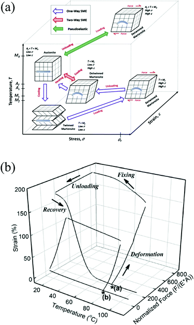 | ||
| Fig. 11 (a) Schematic of the shape-memory process of SMAs.28 Copyright 2014, Elsevier. (b) Schematic of the shape-memory process of SMPs.29 Copyright 2007, Royal Society of Chemistry. | ||
SMPs are a collection of pure polymers, polymer blends, polymer composites and polymer networks. The SME of the SMPs can be illustrated with a 3-D plot of strain vs. temperature and force, as shown in Fig. 11b.29 Beginning at the star (*), SMPs are deformed at an elevated temperature in the presence of an external force or loading. The deformed shape is fixed on cooling. The fixed shape can remain stable for a long time without loading until heated to a temperature above the transition temperature (glass transition temperature Tg for amorphous polymers, melting temperature Tm for crystalline polymers). Compared with SMAs, SMPs are soft (above Tg or Tm), light-weight, cheap, and can be extended to several hundreds of percent. SMPs can memorize more than one shape and recover its original form when subjected to various stimuli, such as vapor, temperature, light, magnetic field, electric current, etc. But the recovery speed of SMPs (from <1 s to several minutes) is longer than that of SMAs (<1 s), and the deformation stress of SMPs is 100-fold lower than that of SMAs.29,86,87
Both SMAs and SMPs have been applied in SCs to introduce the shape-memory function into SCs. The shape-memory materials in a SC usually serve as the substrate or core, with a conducting layer and an active layer attached successively to the surface of the shape-memory substrate or core to make a shape memory electrode. According to different shape-memory materials, the shape-memory SCs are divided into alloy and polymer based devices.
5.2 Shape-memory alloy based SCs
The NiTi SMAs were used in a watchband-like SC.88 The SC was realized with a graphene coated NiTi alloy flake as the negative electrode, an ultrathin MnO2/Ni film as the positive electrode, and a gel electrolyte as the separator. The SCs showed excellent electrochemical stability under both static and dynamic bending tests. The solid-state SC fully recovered the planar shape when heated to the ambient temperature of 25 °C within 550 s. Further, the NiTi based SCs were assembled into a watchband, which could powere a real electronic watch and automatically wrap the human wrist when touching the human body, suggesting potential applications of shape-memory SCs in wearable electronic devices. However, the recovery speed of the shape-memory SC is low, probably because of the stress from the other parts of the SC, such as the positive electrode.Compared with the band-like shape-memory SCs, wire or fiber-shaped SCs possess more design versatility and potential in wearable electronic devices because of the 1D structure and the possibility of bending to any shape.89 NiTi SMA wires were applied as current collectors in a twisted wire shaped shape-memory SC (SMSC), as depicted in Fig. 12a.30 The SC showed a capacitance of 198.2 F g−1 or 75.8 mF cm−2 at a current density of 1 A g−1, which is higher than the values of recently wire-shaped SCs. In addition, the shape recovery process of SMSC was completed within 25 s, while retaining 96% of initial capacitance. After 15 deformation–restoration cycles, the SC recovered 85% of original shape and 86% of initial capacitance. The SCs were readily woven into traditional fabrics to make a smart sleeve, which can memorize its pre-designed shape and automatically curl for cooling when the human body is too hot, as shown in Fig. 12b.
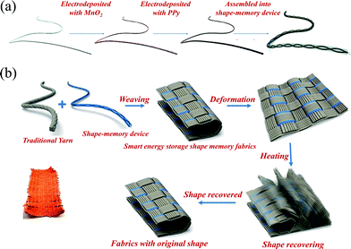 | ||
| Fig. 12 (a) Schematic fabrication process a shape-memory fiber-shaped SC through electrochemical deposition of MnO2 and PPy successively on NiTi fibers and assembly of two fiber electrodes. (b) The schematic process of weaving shape-memory SCs into fabrics and the shape recovery process of the smart fabrics upon heating.30 Copyright 2016, Royal Society of Chemistry. | ||
5.3 Shape-memory polymer based SCs
Compared with SMAs, SMPs are lighter and can endow SCs with reversible deformation of stretching or elongation besides bending. A SWCNT layer and a PANI layer were coated layer-by-layer onto the surface of a wet-spin PVA/CNT composite shape-memory fiber to construct a SC electrode, which can be stretched to a strain of more than 400% and recover most of the original strain (70%) and conductivity after being heated for several minutes.90 Two symmetric composite electrodes were coated with the PVA electrolyte to form a solid state SC, showing a specific capacitance of 427 F cm−3 or 318 F g−1. The shape-memory process recovered the SC to its original length with 30% residual strain and the specific capacitance to 279 F cm−3. The capacitance degradation was due to the cracks of PANI during stretching and the gel electrolyte deterioration under a recovery temperature of 120 °C. Peng et al. made a fiber-shape SC by layer-by-layer assembling of aligned CNT sheets and the PVA based gel electrolyte coaxially onto a PU fiber and comprehensively studied their mechanical and electrochemical performance.91 The SC was able to deform and maintain elongated (max 100%), curvature or complex states combining both elongation and curvature, as shown in Fig. 13a. After heating the SC to above the glass transition temperature, the elongated or bent SC recovered its initial shape with nearly unchanged capacitance during the bending and recovery process. The device can work steadily under a dynamically shape-recovering process (Fig. 13b). Long-term elongation and recovery at a strain of 50% for 500 times also did not obviously harm the electrochemical performance and with only 10% residual strain (Fig. 13c), indicating the excellent stability of the device structure. The fiber-shaped SCs can also be woven into a textile, and the resulting textile could be deformed into any desired shape and size, and can recover its original state reversibly. The specific capacitance of the SC is only 24 F g−1, which can be enhanced by introducing pseudocapacitive materials.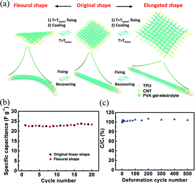 | ||
| Fig. 13 (a) Schematic of the shape-memory fabrics made of shape-memory fiber SCs and the shape fixing and recovering process of the textile from bending and stretching deformation. The capacitance retention during (b) 20 cycles of bending/shape-recovery and (c) 500 cycles of elongation/shape-recovery.91 Copyright 2015, Wiley-VCH. | ||
6. Challenges
Mechanically durable properties including multiple deformable properties and self-healing capability will certainly push forward practical applications of SCs in wearable electronic devices, although there are several challenges in developing high performance durable SCs.Firstly, the evaluation standards of these SCs need to be constructed. In order to rationally and precisely evaluate the electrochemical performance of a SC, it is necessary to include all relevant details: physical, electric and electrochemical parameters of an electrode or SC device. Comprehensive mechanical testing, static and real-time dynamic electrochemical performances should be tested to demonstrate the real performance in a simulative environment.
Secondly, electrochemical performance requires improvement. Most of the mechanical durable and self-healable SCs developed so far do not have satisfactory electrochemical performance, such as capacitance, working voltage, energy density or power density. Incorporation of pseudocapacitive materials, utilization of non-aqueous and gel electrolytes, and free-standing electrodes, etc. are the possible strategies for performance improvement.
Thirdly, the mechanical properties need further improvement. Most compressible SCs encounter capacitance degradation and only endure a volume reduction of 50–60% in compression tests, which is far away from satisfaction. Obvious size shrinkage and mechanical stress decay can be observed after long compression–release cycles. Stronger compressible electrodes are required, which can be realized by optimizing the material compositions and microstructures of electrodes. Recently emerging 3D printing technique makes it possible to design a micrometer-scale periodic structure, which is a totally novel route of fabricating compressible materials, such as graphene aerogel microlattices.92 The healing efficiency and cyclability of self-healable SCs are still low. In particular, the autonomous restoration of conductivity in the electrode is still a bottle neck for the recovery of electrochemical performance. New conductive materials and healing strategies are required. More efforts should be paid to improve the shape-recovery speed and the cyclability of shape-memory SCs through the use of appropriate materials and device structure.
7. Perspective
Besides durability and maintenance-free, wearable electronic devices require high integration to miniaturize the device size and reduce weight. Apart from an energy storage unit, deformable and healable SCs can also serve as a platform for the incorporation of multiple functions to fully take advantage of their special properties.93 There are only some prospects we can imagine, leaving unlimited potential to the future research.Firstly, it is the integration of multiple mechanical properties. Although SCs with one specific mechanical property such as stretchability or compressibility can meet the requirements of many applications, integration of multiple mechanical properties (including healability and shape-memory) into one SC can result in a more adaptable and durable energy storage device. The integration of mechanical properties in SCs can be realized through two strategies: using a multifunctional component in the SC or incorporation with an additional mechanical component. The mechanical properties of those durable SCs can come from three different parts: substrates, electrodes and electrolytes. It is attractive to design novel electrodes, substrates or electrolytes with more than one mechanical property. For example, a self-healing as well as stretchable hydrogel electrolyte was applied to construct a self-healing SC with excellent stretchability at the same time.71 The other strategy is introducing an additional component with more than one mechanical property. PU has been utilized in both a self-healing and shape-memory SC as substrates as discussed above.81,91 With appropriate design and electrode materials, one SC can have self-healing and shape-memory capabilities by using a PU substrate or a shell. For example, integration of three different functions, self-healing, stretchability and compressibility, has been achieved by Huang et al. in the electrolyte based self-healing SC.71 The final goal of mechanical integration may be a superior tough device which is tolerant to all kinds of deformations and self-heals itself when damages occur.
Secondly, it is the incorporation of non-mechanical functions at the level of materials. This can be designed through incorporation with a multifunctional component to integrate non-mechanical functions, such as stimulus alert, fracture alert, transparency, electrochromism, self-powered actuator, etc. So the electrode or electrolyte should be with another function besides electrochemical activity. For example, WO3 and PANI are two typical electrochromic materials and have been utilized in both paper-like and fiber-shaped stretchable and wearable SCs, which can change color through charging/discharging.94–96 Highly integrated supercapacitor-sensor systems are fabricated via material and geometry design, demonstrating sensitivity to both light and strain besides electrochemical storage capability.97 The self-healing and shape memory process are triggered by an external stimulus, self-healable and shape-memory SCs based on those polymers can be light or gas responsive.98,99 The incorporation of capsules containing a color agent can indicate the emergency of cracks or fracture, and mark the accurate injured location in the device.
Thirdly, it is the incorporation of non-mechanical functions at the level of devices. The most straightforward idea is to use the shape-deformable electrodes or SCs as strain sensors.100 Deformation could result in the deformation of the electrode and the gel electrolyte, which is accompanied with changes in the electric conductivity of the electrode and ionic conductivity of the gel electrolyte. Thus, the strain sensor can be realized by connecting the external circuit with the deformable electrode or the whole device. In addition, connecting wearable SCs with light, thermal or mechanical energy conversion devices can expand their applications in wearable electronics.101 Especially, mechanical energy conversion devices such as triboelectric generators or piezoelectric generators can be highly integrated with a stretchable or compressible SC by sharing electrodes, as shown in Fig. 14.102,103 The integrated triboelectric nanogenerator–supercapacitor system can convert the mechanical energy from various types of deformations and store the electric energy into the integrated supercapacitor. A highly integrated piezoelectric nanogenerator–supercapacitor system can harvest and store the electric energy from compression deformation simultaneously.
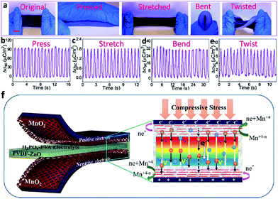 | ||
| Fig. 14 (a) Photographs of a soft and stretchable self-charging power system combining a stretchable SC with a stretchable triboelectric nanogenerator at different deformation states, including original, pressed, stretched, bent and twisted states. (b–e) The short-circuit transferred charge density of the triboelectric nanogenerator part when the device is under pressing, stretching, bending and twisting.102 Copyright 2016, American Chemistry Society. (f) Schema of an integrated self-charging power system combining a compressible SC and a piezoelectric nanogenerator by sharing electrodes.103 Copyright 2015, American Chemistry Society. | ||
8. Conclusion
SMART SCs with strong mechanical durability and self-healing ability have emerged to meet the practical applications of wearable electronic devices. In this review, we give a brief introduction to stretchable SCs, and then introduce the recent progress in compressible, self-healing and shape-memory SCs, respectively, with focus on the device or electrode structure design, functional materials and their working mechanism, and the employed electrolyte. Challenges in front of the deformable and healable SCs are summarized. Both electrochemical and mechanical performance of SMART SCs require improvement. At the same time, SMART SCs with advanced mechanical properties will lead to even more durable and broad-spectrum applications in wearable electronics. Incorporation of multiple functions into mechanically durable SCs will open the door to novel self-powered multi-function devices.Acknowledgements
We acknowledge the support from the National Basic Research Program of China (2015CB932600), National Key Research and Development Program of “Strategic Advanced Electronic Materials” (2016YFB0401100), the National Natural Science Foundation of China (21571073, 51302099, 21673090, 51551205), the Program for New Century Excellent Talents in University (NCET-13-0227), the Program for HUST Interdisplinary Innovation Team (2015ZDTD038) and the Fundamental Research Funds for the Central University. The authors also thank the Analytical and Testing Center of HUST for the measurements.References
- M. F. El-Kady, V. Strong, S. Dubin and R. B. Kaner, Science, 2012, 335, 1326 CrossRef CAS PubMed.
- L. Liu, Y. Yu, C. Yan, K. Li and Z. Zheng, Nat. Commun., 2015, 6, 7260 CrossRef CAS PubMed.
- S. J. Kim, J. H. We and B. J. Cho, Energy Environ. Sci., 2014, 7, 1959 CAS.
- Y. H. Lee, J. S. Kim, J. Noh, I. Lee, H. J. Kim, S. Choi, J. Seo, S. Jeon, T. S. Kim, J. Y. Lee and J. W. Choi, Nano Lett., 2013, 13, 5753 CrossRef CAS PubMed.
- J. Ren, Y. Zhang, W. Bai, X. Chen, Z. Zhang, X. Fang, W. Weng, Y. Wang and H. Peng, Angew. Chem., Int. Ed., 2014, 53, 7864 CrossRef CAS PubMed.
- X. Wang, X. Lu, B. Liu, D. Chen, Y. Tong and G. Shen, Adv. Mater., 2014, 26, 4763 CrossRef CAS PubMed.
- P. Simon, Y. Gogotsi and B. Dunn, Science, 2014, 343, 1210 CrossRef CAS PubMed.
- L. Dong, C. Xu, Y. Li, Z.-H. Huang, F. Kang, Q.-H. Yang and X. Zhao, J. Mater. Chem. A, 2016, 4, 4659 CAS.
- X. Cai, M. Peng, X. Yu, Y. Fu and D. Zou, J. Mater. Chem. C, 2014, 2, 1184 RSC.
- S. L. Candelaria and G. Cao, Sci. Bull., 2015, 60, 1587 CrossRef CAS.
- S. Zhou, J. Chen, L. Gan, Q. Zhang, Z. Zheng, H. Li and T. Zhai, Sci. Bull., 2016, 61, 227 CrossRef CAS.
- J. Bae, M. K. Song, Y. J. Park, J. M. Kim, M. Liu and Z. L. Wang, Angew. Chem., Int. Ed., 2011, 50, 1683 CrossRef CAS PubMed.
- L. Nyholm, G. Nystrom, A. Mihranyan and M. Stromme, Adv. Mater., 2011, 23, 3751 CAS.
- Y. J. Kang, S. J. Chun, S. S. Lee, B. Y. Kim, J. H. Kim, H. Chung, S. Y. Lee and W. Kim, ACS Nano, 2012, 6, 6400 CrossRef CAS PubMed.
- H. Cheng, Z. Dong, C. Hu, Y. Zhao, Y. Hu, L. Qu, N. Chen and L. Dai, Nanoscale, 2013, 5, 3428 RSC.
- Z. Niu, H. Dong, B. Zhu, J. Li, H. H. Hng, W. Zhou, X. Chen and S. Xie, Adv. Mater., 2013, 25, 1058 CrossRef CAS PubMed.
- J. Yu, W. Lu, S. Pei, K. Gong, L. Wang, L. Meng, Y. Huang, J. P. Smith, K. S. Booksh, Q. Li, J. H. Byun, Y. Oh, Y. Yan and T. W. Chou, ACS Nano, 2016, 10, 5204 CrossRef CAS PubMed.
- Z. Zhang, J. Deng, X. Li, Z. Yang, S. He, X. Chen, G. Guan, J. Ren and H. Peng, Adv. Mater., 2015, 27, 356 CrossRef CAS PubMed.
- C. Masarapu, L.-P. Wang, X. Li and B. Wei, Adv. Energy Mater., 2012, 2, 546 CrossRef CAS.
- X. Li, J. Rong and B. Wei, ACS Nano, 2010, 4, 6039 CrossRef CAS PubMed.
- K. Xiao, L. X. Ding, G. Liu, H. Chen, S. Wang and H. Wang, Adv. Mater., 2016, 28, 5997 CrossRef CAS PubMed.
- G. Nystrom, A. Marais, E. Karabulut, L. Wagberg, Y. Cui and M. M. Hamedi, Nat. Commun., 2015, 6, 7259 CrossRef PubMed.
- Y. Yu, C. Yan and Z. Zheng, Adv. Mater., 2014, 26, 5508 CrossRef CAS PubMed.
- H. Sun, X. You, Y. Jiang, G. Guan, X. Fang, J. Deng, P. Chen, Y. Luo and H. Peng, Angew. Chem., Int. Ed., 2014, 53, 9526 CrossRef CAS PubMed.
- V. L. Pushparaj, M. M. Shaijumon, A. Kumar, S. Murugesan, L. Ci, R. Vajtai, R. J. Linhardt, O. Nalamasu and P. M. Ajayan, Proc. Natl. Acad. Sci. U. S. A., 2007, 104, 13574 CrossRef CAS PubMed.
- S. J. Benight, C. Wang, J. B. H. Tok and Z. Bao, Prog. Polym. Sci., 2013, 38, 1961 CrossRef CAS.
- J. Li, J. Liang, L. Li, F. Ren, W. Hu, J. Li, S. Qi and Q. Pei, ACS Nano, 2014, 8, 12874 CrossRef CAS PubMed.
- J. Mohd Jani, M. Leary, A. Subic and M. A. Gibson, Mater. Des., 2014, 56, 1078 CrossRef CAS.
- C. Liu, H. Qin and P. T. Mather, J. Mater. Chem., 2007, 17, 1543 RSC.
- Y. Huang, M. Zhu, Z. Pei, Q. Xue, Y. Huang and C. Zhi, J. Mater. Chem. A, 2016, 4, 1290 CAS.
- C. Yu, C. Masarapu, J. Rong, B. Wei and H. Jiang, Adv. Mater., 2009, 21, 4793 CrossRef CAS PubMed.
- J. Zang, C. Cao, Y. Feng, J. Liu and X. Zhao, Sci. Rep., 2014, 4, 6492 CrossRef CAS PubMed.
- T. Chen, H. Peng, M. Durstock and L. Dai, Sci. Rep., 2014, 4, 3612 Search PubMed.
- I. Nam, S. Bae, S. Park, Y. G. Yoo, J. M. Lee, J. W. Han and J. Yi, Nano Energy, 2015, 15, 33 CrossRef CAS.
- L. Hu, M. Pasta, F. L. Mantia, L. Cui, S. Jeong, H. D. Deshazer, J. W. Choi, S. M. Han and Y. Cui, Nano Lett., 2010, 10, 708 CrossRef CAS PubMed.
- B. Yue, C. Wang, X. Ding and G. G. Wallace, Electrochim. Acta, 2012, 68, 18 CrossRef CAS.
- Y. Lim, J. Yoon, J. Yun, D. Kim, S. Y. Hong, S. J. Lee, G. Zi and J. S. Ha, ACS Nano, 2014, 8, 11639 CrossRef CAS PubMed.
- J. Pu, X. Wang, R. Xu and K. Komvopoulos, ACS Nano, 2016, 10, 9306 CrossRef CAS PubMed.
- P. Xu, B. Wei, Z. Cao, J. Zheng, K. Gong, F. Li, J. Yu, Q. Li, W. Lu, J. H. Byun, B. S. Kim, Y. Yan and T. W. Chou, ACS Nano, 2015, 9, 6088 CrossRef CAS PubMed.
- P. Xu, T. Gu, Z. Cao, B. Wei, J. Yu, F. Li, J.-H. Byun, W. Lu, Q. Li and T.-W. Chou, Adv. Energy Mater., 2014, 4, 1300759 CrossRef.
- J. Sun, Y. Huang, C. Fu, Z. Wang, Y. Huang, M. Zhu, C. Zhi and H. Hu, Nano Energy, 2016, 27, 230 CrossRef CAS.
- C. Choi, H. J. Sim, G. M. Spinks, X. Lepró, R. H. Baughman and S. J. Kim, Adv. Energy Mater., 2016, 6, 1502119 CrossRef.
- Y. Shang, C. Wang, X. He, J. Li, Q. Peng, E. Shi, R. Wang, S. Du, A. Cao and Y. Li, Nano Energy, 2015, 12, 401 CrossRef CAS.
- R. Ma, J. Lee, D. Choi, H. Moon and S. Baik, Nano Lett., 2014, 14, 1944 CrossRef CAS PubMed.
- C. Choi, S. H. Kim, H. J. Sim, J. A. Lee, A. Y. Choi, Y. T. Kim, X. Lepro, G. M. Spinks, R. H. Baughman and S. J. Kim, Sci. Rep., 2015, 5, 9387 CrossRef CAS PubMed.
- H. Jin, L. Zhou, C. L. Mak, H. Huang, W. M. Tang and H. L. W. Chan, Nano Energy, 2015, 11, 662 CrossRef CAS.
- Q. Tang, M. Chen, C. Yang, W. Wang, H. Bao and G. Wang, ACS Appl. Mater. Interfaces, 2015, 7, 15303 CAS.
- J. Yu, W. Lu, J. P. Smith, K. S. Booksh, L. Meng, Y. Huang, Q. Li, J.-H. Byun, Y. Oh, Y. Yan and T.-W. Chou, Adv. Energy Mater., 2016, 1600976 CrossRef.
- C. Yan and P. S. Lee, Small, 2014, 10, 3443 CrossRef CAS PubMed.
- K. Xie and B. Wei, Adv. Mater., 2014, 26, 3592 CrossRef CAS PubMed.
- Z. Niu, W. Zhou, X. Chen, J. Chen and S. Xie, Adv. Mater., 2015, 27, 6002 CrossRef CAS PubMed.
- X. Liu, D. Wu, H. Wang and Q. Wang, Adv. Mater., 2014, 26, 4370 CrossRef CAS PubMed.
- L. Dong, C. Xu, Q. Yang, J. Fang, Y. Li and F. Kang, J. Mater. Chem. A, 2015, 3, 4729 CAS.
- H. Hu, Z. Zhao, W. Wan, Y. Gogotsi and J. Qiu, Adv. Mater., 2013, 25, 2219 CrossRef CAS PubMed.
- H. Sun, Z. Xu and C. Gao, Adv. Mater., 2013, 25, 2554 CrossRef CAS PubMed.
- Y. Xu, K. Sheng, C. Li and G. Shi, ACS Nano, 2010, 4, 4324 CrossRef CAS PubMed.
- L. Qiu, J. Z. Liu, S. L. Y. Chang, Y. Wu and D. Li, Nat. Commun., 2012, 3, 1241 CrossRef PubMed.
- Y. Li, J. Chen, L. Huang, C. Li, J. D. Hong and G. Shi, Adv. Mater., 2014, 26, 4789 CrossRef CAS PubMed.
- Y. Zhao, J. Liu, Y. Hu, H. Cheng, C. Hu, C. Jiang, L. Jiang, A. Cao and L. Qu, Adv. Mater., 2013, 25, 591 CrossRef CAS PubMed.
- S. Ye and J. Feng, ACS Appl. Mater. Interfaces, 2014, 6, 9671 CAS.
- C. Wang, X. He, Y. Shang, Q. Peng, Y. Qin, E. Shi, Y. Yang, S. Wu, W. Xu, S. Du, A. Cao and Y. Li, J. Mater. Chem. A, 2014, 2, 14994 CAS.
- J.-Y. Hong, B. M. Bak, J. J. Wie, J. Kong and H. S. Park, Adv. Funct. Mater., 2015, 25, 1053 CrossRef CAS.
- P. Li, C. Kong, Y. Shang, E. Shi, Y. Yu, W. Qian, F. Wei, J. Wei, K. Wang, H. Zhu, A. Cao and D. Wu, Nanoscale, 2013, 5, 8472 RSC.
- M. B. Bryning, D. E. Milkie, M. F. Islam, L. A. Hough, J. M. Kikkawa and A. G. Yodh, Adv. Mater., 2007, 19, 661 CrossRef CAS.
- K. H. Kim, Y. Oh and M. F. Islam, Nat. Nanotechnol., 2012, 7, 562 CrossRef CAS PubMed.
- E. Wilson and M. F. Islam, ACS Appl. Mater. Interfaces, 2015, 7, 5612 CAS.
- P. Li, E. Shi, Y. Yang, Y. Shang, Q. Peng, S. Wu, J. Wei, K. Wang, H. Zhu, Q. Yuan, A. Cao and D. Wu, Nano Res., 2013, 7, 209 CrossRef.
- X. Cheng, X. Gui, Z. Lin, Y. Zheng, M. Liu, R. Zhan, Y. Zhu and Z. Tang, J. Mater. Chem. A, 2015, 3, 20927 CAS.
- P. Li, Y. Yang, E. Shi, Q. Shen, Y. Shang, S. Wu, J. Wei, K. Wang, H. Zhu, Q. Yuan, A. Cao and D. Wu, ACS Appl. Mater. Interfaces, 2014, 6, 5228 CAS.
- Y. Zhang, Z. Zhen, Z. Zhang, J. Lao, J. Wei, K. Wang, F. Kang and H. Zhu, Electrochim. Acta, 2015, 157, 134 CrossRef CAS.
- Y. Huang, M. Zhong, Y. Huang, M. Zhu, Z. Pei, Z. Wang, Q. Xue, X. Xie and C. Zhi, Nat. Commun., 2015, 6, 10310 CrossRef CAS PubMed.
- S. Y. An, D. Arunbabu, S. M. Noh, Y. K. Song and J. K. Oh, Chem. Commun., 2015, 51, 13058 RSC.
- J. Ahner, S. Bode, M. Micheel, B. Dietzek and M. D. Hager, Adv. Polym. Sci., 2015, 273, 247 CrossRef.
- Y. Sun, J. Lopez, H. W. Lee, N. Liu, G. Zheng, C. L. Wu, J. Sun, W. Liu, J. W. Chung, Z. Bao and Y. Cui, Adv. Mater., 2016, 28, 2455 CrossRef CAS PubMed.
- C. Wang, H. Wu, Z. Chen, M. T. McDowell, Y. Cui and Z. Bao, Nat. Chem., 2013, 5, 1042 CrossRef CAS PubMed.
- S. Bai, C. Sun, H. Yan, X. Sun, H. Zhang, L. Luo, X. Lei, P. Wan and X. Chen, Small, 2015, 11, 5807 CrossRef CAS PubMed.
- T. P. Huynh and H. Haick, Adv. Mater., 2016, 28, 138 CrossRef CAS PubMed.
- K. Guo, D. L. Zhang, X. M. Zhang, J. Zhang, L. S. Ding, B. J. Li and S. Zhang, Angew. Chem., Int. Ed., 2015, 54, 12127 CrossRef CAS PubMed.
- Y. Li, S. Chen, M. Wu and J. Sun, Adv. Mater., 2012, 24, 4578 CrossRef CAS PubMed.
- H. Sun, X. You, Y. Jiang, G. Guan, X. Fang, J. Deng, P. Chen, Y. Luo and H. Peng, Angew. Chem., Int. Ed., 2014, 53, 9526 CrossRef CAS PubMed.
- Y. Huang, Y. Huang, M. Zhu, W. Meng, Z. Pei, C. Liu, H. Hu and C. Zhi, ACS Nano, 2015, 9, 6242 CrossRef CAS PubMed.
- H. Wang, B. Zhu, W. Jiang, Y. Yang, W. R. Leow, H. Wang and X. Chen, Adv. Mater., 2014, 26, 3638 CrossRef CAS PubMed.
- Q. Wang, J. Yan and Z. Fan, Energy Environ. Sci., 2016, 9, 729 CAS.
- C. Zhong, Y. Deng, W. Hu, J. Qiao, L. Zhang and J. Zhang, Chem. Soc. Rev., 2015, 44, 7484 RSC.
- B. Q. Chan, Z. W. Low, S. J. Heng, S. Y. Chan, C. Owh and X. J. Loh, ACS Appl. Mater. Interfaces, 2016, 8, 10070 CAS.
- L. Sun, W. M. Huang, Z. Ding, Y. Zhao, C. C. Wang, H. Purnawali and C. Tang, Mater. Des., 2012, 33, 577 CrossRef CAS.
- T. Xie, Nature, 2010, 464, 267 CrossRef CAS PubMed.
- L. Liu, B. Shen, D. Jiang, R. Guo, L. Kong and X. Yan, Adv. Energy Mater., 2016, 6, 1600763 CrossRef.
- D. Yu, Q. Qian, L. Wei, W. Jiang, K. Goh, J. Wei, J. Zhang and Y. Chen, Chem. Soc. Rev., 2015, 44, 647 RSC.
- J. Zhong, J. Meng, Z. Yang, P. Poulin and N. Koratkar, Nano Energy, 2015, 17, 330 CrossRef CAS.
- J. Deng, Y. Zhang, Y. Zhao, P. Chen, X. Cheng and H. Peng, Angew. Chem., Int. Ed., 2015, 54, 15419 CrossRef CAS PubMed.
- C. Zhu, T. Y. Han, E. B. Duoss, A. M. Golobic, J. D. Kuntz, C. M. Spadaccini and M. A. Worsley, Nat. Commun., 2015, 6, 6962 CrossRef CAS PubMed.
- Y. Huang, M. Zhu, Y. Huang, Z. Pei, H. Li, Z. Wang, Q. Xue and C. Zhi, Adv. Mater., 2016, 28, 8344 CrossRef CAS PubMed.
- C. Yan, W. Kang, J. Wang, M. Cui, X. Wang, C. Y. Foo, K. J. Chee and P. S. Lee, ACS Nano, 2014, 8, 316 CrossRef CAS PubMed.
- X. Chen, H. Lin, P. Chen, G. Guan, J. Deng and H. Peng, Adv. Mater., 2014, 26, 4444 CrossRef CAS PubMed.
- X. Chen, H. Lin, J. Deng, Y. Zhang, X. Sun, P. Chen, X. Fang, Z. Zhang, G. Guan and H. Peng, Adv. Mater., 2014, 26, 8126 CrossRef CAS PubMed.
- Y. Huang, S. V. Kershaw, Z. Wang, Z. Pei, J. Liu, Y. Huang, H. Li, M. Zhu, A. L. Rogach and C. Zhi, Small, 2016, 12, 3393 CrossRef CAS PubMed.
- M. Burnworth, L. Tang, J. R. Kumpfer, A. J. Duncan, F. L. Beyer, G. L. Fiore, S. J. Rowan and C. Weder, Nature, 2011, 472, 334 CrossRef CAS PubMed.
- A. Rose, Z. Zhu, C. F. Madigan, T. M. Swager and V. Bulovic, Nature, 2005, 434, 876 CrossRef CAS PubMed.
- X. Gui, A. Cao, J. Wei, H. Li, Y. Jia, Z. Li, L. Fan, K. Wang, H. Zhu and D. Wu, ACS Nano, 2010, 4, 2320 CrossRef CAS PubMed.
- W. Weng, P. Chen, S. He, X. Sun and H. Peng, Angew. Chem., Int. Ed., 2016, 55, 6140 CrossRef CAS PubMed.
- F. Yi, J. Wang, X. Wang, S. Niu, S. Li, Q. Liao, Y. Xu, Z. You, Y. Zhang and Z. L. Wang, ACS Nano, 2016, 10, 6519 CrossRef CAS PubMed.
- A. Ramadoss, B. Saravanakumar, S. W. Lee, Y. S. Kim, S. J. Kim and Z. L. Wang, ACS Nano, 2015, 9, 4337 CrossRef CAS PubMed.
| This journal is © The Royal Society of Chemistry 2017 |


