Carbon-encapsulated tungsten oxide nanowires as a stable and high-rate anode material for flexible asymmetric supercapacitors†
Chenzhong
Yao
*,
Bohui
Wei
,
Hui
Li
,
Gaofeng
Wang
,
Qiuping
Han
,
Huixuan
Ma
and
Qiaojuan
Gong
*
Department of Applied Chemistry, Yuncheng University, Yuncheng 044000, PR China. E-mail: yaochzh1999@126.com; gqjuan@163.com
First published on 1st November 2016
Abstract
Herein, we report an effective carbon encapsulation strategy to boost the capacitive performance of WO3−x nanowires as a high-energy and stable anode material for flexible asymmetric supercapacitors (ASCs). The carbon-encapsulated WO3−x nanowires exhibited a remarkable areal capacitance of 786.8 mF cm−2 and excellent durability. Furthermore, an ASC device with high energy and power density was also fabricated from the as-prepared carbon encapsulated WO3−x nanowire anode.
To meet the demands and needs of specific environments, the developing trend in electronics is moving towards tiny, lightweight and portable concepts.1–3 In particular, flexible electronics are essential for the advancement in personalized electronics due to their interesting application potentials in highly integrated on-body equipment.4–6 As indispensable parts to power personalized electronics in wearable systems, recently, there has been a rapid increase in the research of flexible energy devices because they are lightweight and can be easily woven into textiles or other structures.1,7–10 Amongst all the energy storage devices, flexible asymmetric supercapacitors (ASCs) have drawn considerable attention for their impressive features of having high energy and power densities, fast charge/discharge capability as well as excellent cycling stability.11–17 However, due to low capacitance of the developed negative electrodes, the energy density of the most current flexible ASCs is yet insufficient.2,18,19 To increase the energy-density limit of ASCs, a state-of-the art anode material with large capacitance and long cycling lifetime is highly desired.
As a typical metal oxide with multiple oxidation states, tungsten oxide (WO3−x) has attracted considerable interest as an electrode material for SCs due to its significant advantages of having high theoretical capacitance and good conductivity, as well as being low-cost and environmentally friendly.20–26 For example, W18O49 nanowires with an areal capacitance of 20 mF cm−2 were obtained via a facile hydrothermal method.25 Park et al. reported a 3D urchin-like W18O49 nanostructured electrode via a simple solvothermal approach and delivered a high specific capacitance of ∼235 F g−1 at 20 A g−1.6 Mai and coworkers also developed a nanoflower-like WO3 electrode with a good electrochemical performance through a facile and effective electrodeposition method, which could achieve an areal capacitance of 458 mF cm−2 at a current density of 14 mA cm−2.27 However, the capacitive performances of these WO3−x electrodes are yet unsatisfactory, especially their cycling stabilities. It is still a great challenge to fabricate high-performance stable WO3−x electrodes.
Herein, we present a smart and effective approach to markedly enhance the electrochemical performance and durability of WO3−x nanowires by encapsulating them in an amorphous carbon shell. Carbon-encapsulated WO3−x (denoted as C@WO3−x) nanowires were obtained by a facile hydrothermal growth and thermal treatment. Their unique structure not only allows for fast charge transport and ion diffusion, but also readily prevents structural pulverization, thus resulting in an excellent electrochemical behavior and cycling performance. The C@WO3−x nanowires exhibited a remarkable areal capacitance of 786.8 mF cm−2 at a high current density of 20 mA cm−2. More importantly, when compared to the cycling stability of pristine WO3 nanowires, the cycling stability of the C@WO3−x nanowires was substantially improved. The former showed a capacitance retention of 7.4% after 10![[thin space (1/6-em)]](https://www.rsc.org/images/entities/char_2009.gif) 000 cycles, whereas the latter showed 87.7%. Additionally, when using the C@WO3−x nanowires as anode, a flexible high-performance ASC device with a remarkable energy density of 1.9 mW h cm−3 and a remarkable power density of 4.1 W cm−3 was demonstrated.
000 cycles, whereas the latter showed 87.7%. Additionally, when using the C@WO3−x nanowires as anode, a flexible high-performance ASC device with a remarkable energy density of 1.9 mW h cm−3 and a remarkable power density of 4.1 W cm−3 was demonstrated.
The schematic of carbon-encapsulated WO3−x nanowires preparation is illustrated in Fig. 1a, and involves two main steps. First, free-standing WO3 nanowires were directly grown on a conductive carbon cloth substrate via a simple hydrothermal process. As shown in Fig. 1b, numerous smooth WO3 nanowires with a diameter of 50–80 nm and a length of up to several micrometers were uniformly coated onto each carbon fiber. The X-ray diffraction (XRD) patterns of the as-prepared WO3 nanowires, as shown in Fig. 1d (lower), suggest that they possess a hexagonal structure (JCPDS = #33-1387) with good crystallinity. Second, these WO3 nanowires were coated with a carbon shell via a hydrothermal method, and then further annealed at 800 °C in a N2 atmosphere for 1 h to obtain the C@WO3−x nanowires. During the calcination process, the hydrothermally derived carbon was pyrolyzed into an amorphous carbon shell of the nanowires, and the WO3 was reduced to WO3−x, which is confirmed by the XRD pattern of the annealed sample, as shown in Fig. 1d (upper). Obviously, all the diffraction peaks are well indexed to monoclinic W18O49 (JCPDF #05-0392), indicating that the WO3 nanowires have been successfully converted into W18O49 nanowires. Scanning electron microscopy (SEM) images, as shown in Fig. 1c, demonstrate that the nanowire-like morphology and smooth surface of these WO3 nanowires are preserved after encapsulating them in a carbon shell.
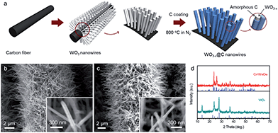 | ||
| Fig. 1 (a) Schematic of the preparation process of the C@WO3−x nanowires. SEM images of the as-prepared (b) WO3 and (c) C@WO3−x nanowires. (d) XRD patterns of the WO3 and C@WO3−x nanowires. | ||
Transmission electron microscopy (TEM) was carried out to study the detailed structure of the as-prepared samples. The representative TEM image of the WO3 nanowire is depicted in Fig. 2a, which shows that the smooth WO3 nanowire has a diameter of about 50 nm. Moreover, the bright and ordered diffraction spots in the selected-area electron diffraction (SAED) pattern confirm the single-crystalline nature of the WO3 nanowires. Fig. 1b is a high-resolution TEM (HRTEM) image of the WO3 nanowire. Clear lattice fringes with d-spacings of 0.36 and 0.39 nm are observed, which agree best with the (110) and (001) planes of hexagonal WO3 (JCPDS = #33-1387). Fig. 1c displays a typical TEM image for a C@WO3−x nanowire. It can be seen that a carbon shell was uniformly coated over the whole nanowire. The SAED pattern inserted in Fig. 2c confirms that the WO3−x nanowire is also highly crystalline. Fig. 2d displays the HRTEM image of a C@WO3−x nanowire. An amorphous carbon layer of ca. 6.7 nm in thickness is uniformly developed on the surface of WO3−x nanowires. The lattice fringes with d-spacings of 0.33 nm and 0.38 nm are well indexed to WO3−x after calcination. Energy dispersive X-ray spectroscopy (EDS) mapping was also conducted, and is shown in Fig. 2e–g. Obviously, W and C are equally distributed on the nanowire, and the distribution of C is mainly located at the outer part of the nanowire, which again demonstrates that the C@WO3−x nanowire has a core–shell structure.
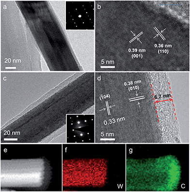 | ||
| Fig. 2 (a) TEM image and (b) HRTEM image of the WO3 nanowire. (c) TEM image, (d) HRTEM image, (e) HAADF-STEM image, (f) W elemental mapping and (g) C elemental mapping of the C@WO3−x nanowire. | ||
X-ray photoelectron spectroscopy (XPS) analysis was performed to study the composition and surface state of the C@WO3−x nanowires. Fig. 3a compares the XPS survey spectra of the WO3 and C@WO3−x samples. In comparison to the pristine WO3 sample, the C single of the C@WO3−x sample is substantially enhanced whereas the W and O singles are weaker, confirming that the carbon shell is successfully deposited onto the WO3−x nanowires. Fig. 3b presents the high-resolution W 4f XPS spectra of the WO3 and C@WO3−x samples. For WO3 nanowires, two well-defined peaks located at about 35.8 and 37.9 eV, corresponding to W 4f7/2 and W 4f5/2, respectively, are observed. These values are consistent with those of the W6+ state in oxides,25,28 and agree well with the XRD results. After coating with the carbon shell, two different peaks at the low binding energies of 34.1 eV (W 4f7/2) and 36.1 eV (W 4f5/2) are detected, which is associated with the lower oxidation states of W.28–30 Moreover, as shown in Fig. 3c, the substantially decreased intensity of the O1s peak for the C@WO3−x nanowires again reveals that the carbon shell was uniformly coated onto the WO3−x nanowires.
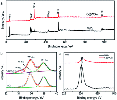 | ||
| Fig. 3 (a) XPS survey spectra, (b) W 4f core level XPS spectra and (c) O1s core level XPS spectra of the WO3 and C@WO3−x nanowires. | ||
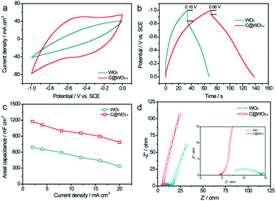
To investigate the capacitive performance of our samples, we first conducted the electrochemical measurements in a three-electrode cell with a Pt electrode as the counter electrode and a saturated calomel electrode (SCE) as the reference electrode in 5 M LiCl aqueous electrolyte. Cyclic voltammograms (CV) of the WO3 and C@WO3−x nanowire electrodes at a scan rate of 100 mV s−1 were obtained, as shown in Fig. 4a. Remarkably, the C@WO3−x electrode exhibited a substantially larger current density and a more rectangular shape than the pristine WO3 electrode, demonstrating the dramatically improved capacitive performance of the C@WO3−x nanowires. Fig. S1† shows the CV curves for the C@WO3−x electrode obtained at different scan rates. The unchanged shapes of these CV curves, even at 100 mV s−1, indicates the good capacitive reversibility and rate capability of the C@WO3−x electrode. Fig. 4b displays the galvanostatic charge and discharge (GCD) curves of the WO3 and C@WO3−x electrodes, obtained at a current density of 12 mA cm−2. The longer discharge time of the C@WO3−x electrode compared to that of the WO3 electrode again confirmed its superior capacitive performance. Furthermore, the IR drop for the C@WO3−x electrode was only 0.06 V, which is much smaller than that of the WO3 electrode (0.16 V), shows the improved conductivity of the C@WO3−x electrode. In Fig. 4c the areal capacitances of the WO3 and C@WO3−x electrodes are plotted against different discharge current densities. The areal capacitances of the C@WO3−x electrode are considerably larger than those of the WO3 electrode. For example, the areal capacitance of the C@WO3−x electrode at a current density of 20 mA cm−2 was 786.8 mF cm−2, whereas that for the WO3 electrode was only 336.2 mF cm−2. The presented values of areal capacitance for the C@WO3−x electrode are substantially higher than the values for recently obtained tungsten-based electrodes23–25,27,31,32 such as WO3−x/MoO3−x core shell nanowires (∼203 mF cm−2 at 20 mA cm−2),33 porous WON nanowires (∼134 mF cm−2 at 20 mA cm−2)34 and other carbon-coated electrodes.33,34 More importantly, the C@WO3−x electrode also exhibited an outstanding rate capability. When the current density increases from 2 to 20 mA cm−2, the C@WO3−x electrode was able to retain more than 66.8% of its initial capacitance, which is significantly higher to that of the WO3 electrode (50.1%) and other recent electrodes. Considering that the thick carbon layer can restrain the ions in the electrolyte to penetrate through it and react with the active materials,35,36 we also studied the influence of the shell thickness on the capacitance of the C@WO3−x electrode. By prolonging the hydrothermal time to 9 h, we were able to obtain a type of C@WO3−x nanowires with a carbon shell thickness of about 14.5 nm (Fig. S2a–2c). We found that the capacitance of these C@WO3−x nanowires obviously decreased when the thickness of carbon shell increased to 14.5 nm (Fig. S2d†). Thus, a carbon shell with the appropriate thickness is important for improving its capacitive performance.
To better understand the effect of phase transformation and carbon coating on the electrochemical properties of the C@WO3−x electrode, electrochemical impedance spectroscopy (EIS) analyses were performed. Fig. 4d compares the Nyquist plots of WO3 and C@WO3−x electrodes. Both electrodes exhibited a semicircle in the high frequency region and a straight line in the low-frequency region, which correspond to the electron-transfer-limited processes and diffusion-limited electron transfer processes, respectively. Compared with the WO3 electrode, the C@WO3−x electrode exhibited a much smaller charge transfer resistance (the diameter of the semicircle in the impedance spectrum), which indicates the enhanced conductivity of the C@WO3−x electrode. Moreover, the larger slope on the Nyquist plot of C@WO3−x electrode, when compared to that of the WO3 electrode, also reveals its superior ion transport.
The long-term stability of the WO3 and C@WO3−x nanowire electrodes were evaluated at 100 mV s−1 for 10![[thin space (1/6-em)]](https://www.rsc.org/images/entities/char_2009.gif) 000 cycles. As shown in Fig. 5a, the WO3 electrode suffered from fast and drastic capacitance decay, which agrees well with the electrochemical behavior of the previous WO3 electrodes. After 10
000 cycles. As shown in Fig. 5a, the WO3 electrode suffered from fast and drastic capacitance decay, which agrees well with the electrochemical behavior of the previous WO3 electrodes. After 10![[thin space (1/6-em)]](https://www.rsc.org/images/entities/char_2009.gif) 000 cycles, only 7.4% of the initial capacitance remained. This markedly decreased capacitance is primarily due to the structural breakdown of the WO3 nanowires during the charge/discharge cycling process, which is further confirmed by the SEM image (Fig. 5b). The WO3 nanowires basically disappeared and only some nanoparticles were anchored onto the carbon fibers after 10
000 cycles, only 7.4% of the initial capacitance remained. This markedly decreased capacitance is primarily due to the structural breakdown of the WO3 nanowires during the charge/discharge cycling process, which is further confirmed by the SEM image (Fig. 5b). The WO3 nanowires basically disappeared and only some nanoparticles were anchored onto the carbon fibers after 10![[thin space (1/6-em)]](https://www.rsc.org/images/entities/char_2009.gif) 000 cycles. In contrast, the C@WO3−x electrode delivered a prominent long-term cycling durability, with more than 87.7% capacitance retention after 10
000 cycles. In contrast, the C@WO3−x electrode delivered a prominent long-term cycling durability, with more than 87.7% capacitance retention after 10![[thin space (1/6-em)]](https://www.rsc.org/images/entities/char_2009.gif) 000 cycles. This value is also comparable to the values of other WO3−x-based electrodes.6,27,31 SEM images in Fig. 5 and TEM images in Fig. S3† show that the nanowire-like morphology of the C@WO3−x electrode is mostly retained after long-term cycling, clearly demonstrating that this thin carbon layer can significantly protect the nanowires from the structural pulverization. Such remarkably enhanced capacitive performance and durability of the C@WO3−x nanowires in a neutral electrolyte is attributed to the synergistic effect of the thin amorphous carbon shell and the fact that WO3−x is more conductive than WO3.
000 cycles. This value is also comparable to the values of other WO3−x-based electrodes.6,27,31 SEM images in Fig. 5 and TEM images in Fig. S3† show that the nanowire-like morphology of the C@WO3−x electrode is mostly retained after long-term cycling, clearly demonstrating that this thin carbon layer can significantly protect the nanowires from the structural pulverization. Such remarkably enhanced capacitive performance and durability of the C@WO3−x nanowires in a neutral electrolyte is attributed to the synergistic effect of the thin amorphous carbon shell and the fact that WO3−x is more conductive than WO3.
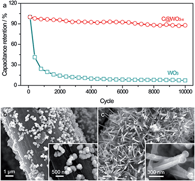 | ||
Fig. 5 (a) Cycling performance of the WO3 and C@WO3−x nanowires at 100 mV s−1 as a function of cycle number. SEM images of the (b) WO3 and (c) C@WO3−x nanowires after 10![[thin space (1/6-em)]](https://www.rsc.org/images/entities/char_2009.gif) 000 cycles. 000 cycles. | ||
To test the potential application of the C@WO3−x nanowires as a negative electrode in a ASC device, a simple ASC device was designed by using TiN/MnO2 nanorods as the positive electrode, the as-prepared C@WO3−x nanowires as the negative electrode and PVA/LiCl gel as the electrolyte (denoted as TiN/MnO2//C@WO3−x). TiN/MnO2 core–shell nanorods were prepared by electrodepositing amorphous MnO2 onto the surface of TiN nanowires (ESI†). Representative SEM and TEM images of the TiN/MnO2 nanorods are shown in Fig. S4,† which confirms the core–shell structure of the TiN/MnO2 nanorods. Moreover, an XPS analysis was also performed to confirm that these nanorods are made of TiN and MnO2 (Fig. S4d†). Before the fabrication of the ASC device, the charge between the C@WO3−x electrode and the TiN/MnO2 electrode had to be adjusted. From Fig. 6a, the C@WO3−x electrode area to TiN/MnO2 electrode area ratio was determined to be 1![[thin space (1/6-em)]](https://www.rsc.org/images/entities/char_2009.gif) :
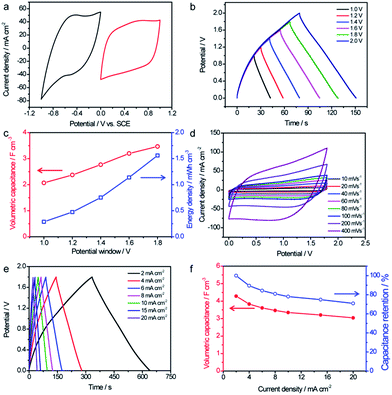
:![[thin space (1/6-em)]](https://www.rsc.org/images/entities/char_2009.gif) 1. Since C@WO3−x and TiN/MnO2 possess stable voltage windows from 0 to 0.8 V and from 0 to −1 V, respectively, it was expected that the operating cell voltage could be extended to 1.8 V if assembled into an ASCs. Fig. 6b shows the GCD curves for our optimized TiN/MnO2//C@WO3−x ASC, obtained at 8 mA cm−2 with different voltage windows. Indeed, this device was not stable when the voltage exceeded 1.8 V (Fig. S5†), and its maximum stable electrochemical voltage was 1.8 V. In addition, as the voltage increased from 1.0 V to 1.8 V, the volumetric capacitance considerably increased from 2.1 F cm−3 to 3.47 F cm−3 (Fig. 6c), whereas the energy density was remarkably enhanced from 0.28 mW h cm−3 to 1.56 mW h cm−3 (both based on the volume of the entire device).
1. Since C@WO3−x and TiN/MnO2 possess stable voltage windows from 0 to 0.8 V and from 0 to −1 V, respectively, it was expected that the operating cell voltage could be extended to 1.8 V if assembled into an ASCs. Fig. 6b shows the GCD curves for our optimized TiN/MnO2//C@WO3−x ASC, obtained at 8 mA cm−2 with different voltage windows. Indeed, this device was not stable when the voltage exceeded 1.8 V (Fig. S5†), and its maximum stable electrochemical voltage was 1.8 V. In addition, as the voltage increased from 1.0 V to 1.8 V, the volumetric capacitance considerably increased from 2.1 F cm−3 to 3.47 F cm−3 (Fig. 6c), whereas the energy density was remarkably enhanced from 0.28 mW h cm−3 to 1.56 mW h cm−3 (both based on the volume of the entire device).
CV and GCD curves with a range of potential windows between 0 and 1.8 V at various scan rates and current densities were obtained to thoroughly assess the electrochemical performance of the TiN/MnO2//C@WO3−x ASC device. All CV curves, shown in Fig. 6d, presented rectangle-like shapes, revealing their perfect capacitive performance and excellent charge/discharge capability. Furthermore, as displayed in Fig. 6e, the GCD curves collected at various current densities showed symmetrical triangular shapes, again confirming the outstanding electrochemical properties of the as-fabricated ASC device. The volumetric capacitances calculated based on the discharge current densities and rate performances of the TiN/MnO2//C@WO3−x ASC device are shown in Fig. 6d. Significantly, our ASC device reached a remarkable volumetric capacitance of 4.28 F cm−3 at 2 mA cm−2, which is substantially higher than the volumetric capacitance achieved by most of the recently reported ASCs at the same current density25,27,34,37,38 such as TiO2@C@PPy//WO3 (1.47 F cm−3),27 MnO2//Ti–Fe2O3 PEDOT-ASCs (∼2.0 F cm−3),37 RGO@MnO2//VOS-ASCs (1.62 F cm−3),25 MnO2//WON-ASCs (2.2 F cm−3 at 2 mA cm−2),34etc. Additionally, a volumetric capacitance of more than 3.04 F cm−3, which is about 71% of its initial capacitance, was still retained when the current density increased to 20 mA cm−2, demonstrating the superior rate capability of this ASC.
Ragone plots of the TiN/MnO2//C@WO3−x-ASC device along with those of some latest ASC devices are shown in Fig. 7a, to comprehensively compare the energies and power densities. Note that our TiN/MnO2//C@WO3−x-ASC device was able to deliver a maximum volumetric energy density of up to 1.9 mW h cm−3 at a power density of 3.33 W cm−3 (with a current density of 2 mA cm−2). This value is comparable or higher than the values obtained for recently reported ASC devices25,33,34,37,39–45 such as ZnO@MnO2//RGO-ASCs (0.24 mW h cm−3),39 MnO2−x//RGO-ASCs (0.25 mW h cm−3),41 MnO2//N–Fe2O3-ASCs (0.41 mW h cm−3),42 TiO2@C@PPy//WO3-ASCs (0.53 mW h cm−3),27 MnO2@Ti–Fe2O3@PEDOT-ASCs (0.89 mW h cm−3),37 VOx//VN-ASCs (0.61 mW h cm−3),43 Fe3O4@MnO2//Fe3O4@Fe2O3-ASC (0.83 mW h cm−3),44 RGO@MnO2//VOS-ASCs (0.87 mW h cm−3),25 TiN@MnO2//electrochemically-activated carbon cloth (EACC)-ASCs (1.5 mW h cm−3),45 MnO2/WNO-ASCs (1.06 mW h cm−3)34 and PANI//WO3−x/MoO3−x (1.9 mW h cm−3).33 In addition, our fabricated ASC device achieved a maximum volumetric power density of 4.1 W cm−3 at a high energy density of 1.24 mW h cm−3, which is considerably higher than that of other ASCs.25,33,34,37,39–45 The long term cycling performance test for the TiN/MnO2//C@WO3−x-ASC device was conducted at 100 mV s−1 for 10![[thin space (1/6-em)]](https://www.rsc.org/images/entities/char_2009.gif) 000 cycles. As shown in Fig. S5,† the ASCs exhibited a remarkable stability with a 89.4% retention of the initial capacitance. Finally, to illustrate the advantages of our ASC device as a flexible energy-storage device, CV curves of the TiN/MnO2//C@WO3−x-ASC device under different bent conditions were obtained, and are shown in Fig. 7b. There is no obvious variation among these CV curves; thus, the as prepared ASC holds great promise in flexible electronics.
000 cycles. As shown in Fig. S5,† the ASCs exhibited a remarkable stability with a 89.4% retention of the initial capacitance. Finally, to illustrate the advantages of our ASC device as a flexible energy-storage device, CV curves of the TiN/MnO2//C@WO3−x-ASC device under different bent conditions were obtained, and are shown in Fig. 7b. There is no obvious variation among these CV curves; thus, the as prepared ASC holds great promise in flexible electronics.
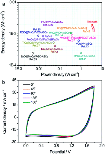 | ||
| Fig. 7 (a) Ragone plots of the TiN/MnO2//C@WO3−x-ASC. The values reported for other ASC devices are added for comparison.25,28,33,34,37,39,41–45 (b) CV curves of the TiN/MnO2//C@WO3−x-ASC device under different bent conditions at 100 mV s−1. | ||
Conclusion
In summary, we have demonstrated that the capacitive performance and cycling stability of the WO3−xnanowires could be significantly increased by carbon encapsulation and their great potential as a high-performance anode for flexible ASCs. The areal capacitance of the C@WO3−xnanowires was achieved (786.8 mF cm−2) at a high current density of 20 mA cm−2, which is much higher than that of the pristine WO3 nanowires. Furthermore, the C@WO3−xnanowires exhibited an extraordinary high rate capability and long-term durability, with more than 87.7% retention after 10![[thin space (1/6-em)]](https://www.rsc.org/images/entities/char_2009.gif) 000 cycles. In addition, a flexible ASC device with an excellent electrochemical performance was successfully fabricated, based on the as-obtained C@WO3−xnanowires (as the anode) and a TiN/MnO2 cathode. The TiN/MnO2//C@WO3−x-ASC device was able to deliver a remarkable volumetric energy density of 1.9 mW h cm−3 and a prominent charge/discharge capability. Such findings offer new opportunities to design other high-performance and stable electrode materials for energy storage applications.
000 cycles. In addition, a flexible ASC device with an excellent electrochemical performance was successfully fabricated, based on the as-obtained C@WO3−xnanowires (as the anode) and a TiN/MnO2 cathode. The TiN/MnO2//C@WO3−x-ASC device was able to deliver a remarkable volumetric energy density of 1.9 mW h cm−3 and a prominent charge/discharge capability. Such findings offer new opportunities to design other high-performance and stable electrode materials for energy storage applications.
Acknowledgements
We thank the Natural Science Foundation of China (Grant No. 21576230) for the financial support.Notes and references
- X. Xia, Y. Zhang, D. Chao, Q. Xiong, Z. Fan, X. Tong, J. Tu, H. Zhang and H. J. Fan, Energy Environ. Sci., 2015, 8, 1559–1568 CAS.
- M. Yu, X. Cheng, Y. Zeng, Z. Wang, Y. Tong, X. Lu and S. Yang, Angew. Chem., Int. Ed., 2016, 55, 6762–6766 CrossRef CAS PubMed.
- Z. Wang, Y. Han, Y. Zeng, Y. Qie, Y. Wang, D. Zheng, X. Lu and Y. Tong, J. Mater. Chem. A, 2016, 4, 5828–5833 CAS.
- X. Xia, Y. Zhang, Z. Fan, D. Chao, Q. Xiong, J. Tu, H. Zhang and H. J. Fan, Adv. Energy Mater., 2015, 5, 1401709 CrossRef.
- G. Shen, S.-H. Yu, Y. Xia and X. W. D. Lou, J. Mater. Chem. A, 2014, 2, 10710–10711 CAS.
- J. W. Park, W. Na and J. Jang, J. Mater. Chem. A, 2016, 4, 8263–8271 CAS.
- L. Shen, Q. Che, H. Li and X. Zhang, Adv. Funct. Mater., 2014, 24, 2630–2637 CrossRef CAS.
- R. Li, Z. Lin, X. Ba, Y. Li, R. Ding and J. Liu, Nanoscale Horiz., 2016, 1, 150–155 RSC.
- L. Shen, L. Yu, X.-Y. Yu, X. Zhang and X. W. Lou, Angew. Chem., Int. Ed., 2015, 54, 1868–1872 CrossRef CAS PubMed.
- P. Yang, Y. Li, Z. Lin, Y. Ding, S. Yue, C. P. Wong, X. Cai, S. Tan and W. Mai, J. Mater. Chem. A, 2014, 2, 595–599 CAS.
- L. Li, S. Peng, H. B. Wu, L. Yu, S. Madhavi and X. W. D. Lou, Adv. Energy Mater., 2015, 5, 1500753 CrossRef.
- J. Liu, M. Zheng, X. Shi, H. Zeng and H. Xia, Adv. Funct. Mater., 2016, 26, 919–930 CrossRef CAS.
- S. Peng, L. Li, H. B. Wu, S. Madhavi and X. W. Lou, Adv. Energy Mater., 2015, 5, 1401172 CrossRef.
- W. Zuo, C. Wang, Y. Li and J. Liu, Sci. Rep., 2015, 5, 7780 CrossRef CAS PubMed.
- X. Yang, H. Niu, H. Jiang, Q. Wang and F. Qu, J. Mater. Chem. A, 2016, 4, 11264–11275 CAS.
- G.-F. Chen, Y.-Z. Su, P.-Y. Kuang, Z.-Q. Liu, D.-Y. Chen, X. Wu, N. Li and S.-Z. Qiao, Chem.–Eur. J., 2015, 21, 4614–4621 CrossRef CAS PubMed.
- Z. Su, C. Yang, C. Xu, H. Wu, Z. Zhang, T. Liu, C. Zhang, Q. Yang, B. Li and F. Kang, J. Mater. Chem. A, 2013, 1, 12432–12440 CAS.
- W. Xu, J. Chen, M. Yu, Y. Zeng, Y. Long, X. Lu and Y. Tong, J. Mater. Chem. A, 2016, 4, 10779–10785 CAS.
- X. Xia, C. Zhu, J. Luo, Z. Zeng, C. Guan, C. F. Ng, H. Zhang and H. J. Fan, Small, 2014, 10, 766–773 CrossRef CAS PubMed.
- L. Shen, L. Du, S. Tan, Z. Zang, C. Zhao and W. Mai, Chem. Commun., 2016, 52, 6296–6299 RSC.
- C. Jo, J. Hwang, H. Song, A. H. Dao, Y.-T. Kim, S. H. Lee, S. W. Hong, S. Yoon and J. Lee, Adv. Funct. Mater., 2013, 23, 3747–3754 CrossRef CAS.
- X. Lu, T. Zhai, X. Zhang, Y. Shen, L. Yuan, B. Hu, L. Gong, J. Chen, Y. Gao and J. Zhou, Adv. Mater., 2012, 24, 938–944 CrossRef CAS PubMed.
- S. Cong, Y. Tian, Q. Li, Z. Zhao and F. Geng, Adv. Mater., 2014, 26, 4260–4267 CrossRef CAS PubMed.
- X. Huang, H. Liu, X. Zhang and H. Jiang, ACS Appl. Mater. Interfaces, 2015, 7, 27845–27852 CAS.
- T. Zhai, X. Lu, Y. Ling, M. Yu, G. Wang, T. Liu, C. Liang, Y. Tong and Y. Li, Adv. Mater., 2014, 26, 5869–5875 CrossRef CAS PubMed.
- B. Zou, S. Gong, Y. Wang and X. Liu, J. Nanomater., 2014, 2014, 3 Search PubMed.
- M. Qiu, P. Sun, L. Shen, K. Wang, S. Song, X. Yu, S. Tan, C. Zhao and W. Mai, J. Mater. Chem. A, 2016, 4, 7266–7273 CAS.
- Y. M. Zhao, W. B. Hu, Y. D. Xia, E. F. Smith, Y. Q. Zhu, C. W. Dunnill and D. H. Gregory, J. Mater. Chem., 2007, 17, 4436–4440 RSC.
- T. Nakajima, K. Watanabe and N. Watanabe, J. Electrochem. Soc., 1987, 134, 3175–3178 CrossRef CAS.
- H.-T. Chiu and S.-H. Chuang, J. Mater. Res., 1993, 8, 1353–1360 CrossRef CAS.
- S. Yoon, E. Kang, J. K. Kim, C. W. Lee and J. Lee, Chem. Commun., 2011, 47, 1021–1023 RSC.
- M. Zhu, W. Meng, Y. Huang, Y. Huang and C. Zhi, ACS Appl. Mater. Interfaces, 2014, 6, 18901–18910 CAS.
- X. Xiao, T. Ding, L. Yuan, Y. Shen, Q. Zhong, X. Zhang, Y. Cao, B. Hu, T. Zhai, L. Gong, J. Chen, Y. Tong, J. Zhou and Z. L. Wang, Adv. Energy Mater., 2012, 2, 1328–1332 CrossRef CAS.
- M. Yu, Y. Han, X. Cheng, L. Hu, Y. Zeng, M. Chen, F. Cheng, X. Lu and Y. Tong, Adv. Mater., 2015, 27, 3085–3091 CrossRef CAS PubMed.
- G. Wang, L. Zhang and J. Zhang, Chem. Soc. Rev., 2012, 41, 797–828 RSC.
- R. Zou, M. F. Yuen, L. Yu, J. Hu, C.-S. Lee and W. Zhang, Sci. Rep., 2016, 6, 20264 CrossRef CAS PubMed.
- Y. X. Zeng, Y. Han, Y. T. Zhao, Y. Zeng, M. H. Yu, Y. J. Liu, H. L. Tang, Y. X. Tong and X. H. Lu, Adv. Energy Mater., 2015, 5, 1402176 CrossRef.
- C. Yang, J. Shen, C. Wang, H. Fei, H. Bao and G. Wang, J. Mater. Chem. A, 2014, 2, 1458–1464 CAS.
- W. Zilong, Z. Zhu, J. Qiu and S. Yang, J. Mater. Chem. C, 2014, 2, 1331–1336 RSC.
- X.-F. Lu, X.-Y. Chen, W. Zhou, Y.-X. Tong and G.-R. Li, ACS Appl. Mater. Interfaces, 2015, 7, 14843–14850 CAS.
- T. Zhai, S. Xie, M. Yu, P. Fang, C. Liang, X. Lu and Y. Tong, Nano Energy, 2014, 8, 255–263 CrossRef CAS.
- X. Lu, Y. Zeng, M. Yu, T. Zhai, C. Liang, S. Xie, M. S. Balogun and Y. Tong, Adv. Mater., 2014, 26, 3148–3155 CrossRef CAS PubMed.
- X. Lu, M. Yu, T. Zhai, G. Wang, S. Xie, T. Liu, C. Liang, Y. Tong and Y. Li, Nano Lett., 2013, 13, 2628–2633 CrossRef CAS PubMed.
- X. Tang, R. Jia, T. Zhai and H. Xia, ACS Appl. Mater. Interfaces, 2015, 7, 27518–27525 CAS.
- W. Wang, W. Y. Liu, Y. X. Zeng, Y. Han, M. H. Yu, X. H. Lu and Y. X. Tong, Adv. Mater., 2015, 27, 3572–3578 CrossRef CAS PubMed.
Footnote |
| † Electronic supplementary information (ESI) available. See DOI: 10.1039/c6ta08274b |
| This journal is © The Royal Society of Chemistry 2017 |

