 Open Access Article
Thermal optimisation of metal hydride reactors for thermal energy storage applications
D.
Dong
a,
T. D.
Humphries
 *a,
D. A.
Sheppard
a,
B.
Stansby
a,
M.
Paskevicius
 a,
M. V.
Sofianos
a,
A.-L.
Chaudhary
a,
M. V.
Sofianos
a,
A.-L.
Chaudhary
 b,
M.
Dornheim
b and
C. E.
Buckley
 a
a
aDepartment of Physics and Astronomy, Fuels and Energy Technology Institute, Curtin University, GPO Box U1987, Perth, WA 6845, Australia. E-mail: terry_humphries81@hotmail.com
bDepartment of Nanotechnology, Institute of Materials Research, Helmholtz-Zentrum Geesthacht, Max-Planck Strasse 1, D-21502 Geesthacht, Germany
First published on 31st August 2017
Abstract
Metal hydrides (MHs) are promising candidates as thermal energy storage (TES) materials for concentrated solar thermal applications. A key requirement for this technology is a high temperature heat transfer fluid (HTF) that can deliver heat to the MHs for storage during the day, and remove heat at night time to produce electricity. In this study, supercritical water was used as a HTF to heat a prototype thermochemical heat storage reactor filled with MgH2 powder during H2 sorption, rather than electrical heating of the MH reactor. This is beneficial as the HTF flows through a coil of tubing embedded within the MH bed and is hence in better contact with the MgH2 powder. This internal heating mode produces a more uniform temperature distribution within the reactor by increasing the heat exchange surface area and reducing the characteristic heat exchange distances. Moreover, supercritical water can be implemented as a heat carrier for the entire thermal energy system within a concentrating solar thermal plant, from the receiver, through the heat storage system, and also within a conventional turbine-driven electric power generation system. Thus, the total system energy efficiency can be improved by minimising HTF heat exchangers.
1. Introduction
Solar energy is one of the cleanest and most abundant energy sources on Earth. Harnessing this resource in a cost effective and efficient manner has been under development for many years with solar photovoltaic (PV) cells and concentrating solar thermal power (CSP) being the foremost methods.1 PV cells are widely implemented in households and businesses around the world as they are cost and space effective and many households have been financially compensated for contributing electricity to the grid. On a global scale, traditional silicon PV cells are realistically unable to become the dominant energy supply in the long-term as each solar cell uses about 0.17 g cm−2 of arsenic during manufacture.1 As the world reserve base of arsenic lies at as little as 3 million tonnes, fixed-lifetime solar panels are not currently sustainable, even without considering the other chemicals required to manufacture solar cells, each of which are essential to fabricate many other devices.CSP plants use a more low-tech method of harnessing solar power and have been developed and deployed over the last two decades. As of February 2016, the CSP market had a total capacity of 7.4 GW worldwide, where 5 GW is operational and 2.4 GW is under construction.2,3 This process uses mirror arrays to focus sunlight and concentrate heat onto a fluid or a gas within a receiver that is then used to either drive a Stirling engine or run a steam turbine to produce electricity.4 The largest CSP plant currently in operation is the Ivanpah Solar Power Facility (California, USA), costing US $2.2 bn to construct, and has a maximum electrical output of 392 MW.5 Two problems exist within the Ivanpah setup, one being that natural gas is required to be burned to start the plant each morning and that, two, energy is not produced 24 hours per day due to solar intermittency. To bypass this situation thermal energy storage (TES) has and continues to be implemented at a number of CSP plants including the Crescent Dunes Solar Energy Project, which has 10 h of TES power production at full load with a maximum electrical output of 110 MW.6 In a typical industrial scale solar array with heat storage capabilities, the thermal energy is stored via the specific heat capacity of molten salt mixtures (40% NaNO3; 60% KNO3). In Crescent Dunes, this thermal storage is supplied by 32![[thin space (1/6-em)]](https://www.rsc.org/images/entities/char_2009.gif) 000 tons of molten nitrate salts that are heated up to 565 °C as it is pumped through the central receiver. The Crescent Dunes project allows Solar Reserve to sell electricity for US $0.135 per kW hel: a price that, without subsidies, makes it competitive with conventional fossil fuel power generation.7 The Commonwealth Scientific and Industrial Research Organisation (CSIRO) in Australia also demonstrated that CSP could be used to generate supercritical steam/water directly from the solar receiver, which is compatible with conventional supercritical steam turbines.8,9
000 tons of molten nitrate salts that are heated up to 565 °C as it is pumped through the central receiver. The Crescent Dunes project allows Solar Reserve to sell electricity for US $0.135 per kW hel: a price that, without subsidies, makes it competitive with conventional fossil fuel power generation.7 The Commonwealth Scientific and Industrial Research Organisation (CSIRO) in Australia also demonstrated that CSP could be used to generate supercritical steam/water directly from the solar receiver, which is compatible with conventional supercritical steam turbines.8,9
Molten salts are currently the first generation of heat storage materials (60 wt% NaNO3, 40 wt% KNO3), but their low heat storage capacity (∼167 kJ kg−1 for parabolic trough configurations operating between 290 and 400 °C and ∼414 kJ kg−1 for a power tower operating between 290 and 565 °C) translates to large volumes of material required at a large cost.6,10 For instance, the 32![[thin space (1/6-em)]](https://www.rsc.org/images/entities/char_2009.gif) 000 tonnes of molten salts implemented at Crescent Dunes is estimated to cost between 10 and 15% of the US $1 bn project cost.11 In addition, the salt mixtures are corrosive and freeze below 200 °C and, most importantly, have a maximum operating temperature of 565 °C that inhibits improvements in efficiency that could be gained by operating at higher temperatures.
000 tonnes of molten salts implemented at Crescent Dunes is estimated to cost between 10 and 15% of the US $1 bn project cost.11 In addition, the salt mixtures are corrosive and freeze below 200 °C and, most importantly, have a maximum operating temperature of 565 °C that inhibits improvements in efficiency that could be gained by operating at higher temperatures.
More recently, metal hydride (MH) systems have been investigated as a class of TES materials as they can reversibly form over a wide range of temperatures including those compatible with CSP.10,12–15 During day operation, the MH (i.e. MgH2 in this study) is heated using the excess energy produced by the heliostat promoting the endothermic desorption of hydrogen gas. At night, when the system cools, the hydrogen is reabsorbed by the TES material (i.e. Mg in this study) in an exothermic reaction. As such, the thermochemical energy released at night can be used to heat a HTF and run a steam turbine to produce electricity. Engineering concepts for these materials have already been considered, including reactor design, heat management and heat transfer limitations.16–18
Technological and cost analyses have been undertaken to determine the feasibility of MH TES materials compared to current molten salt technology. The optimum economic target set by the US Department of Energy for electric production cost is 0.06 $ per kW h.19 A recent screening analysis study has shown that MH TES are highly competitive with molten salt systems, with specific installed costs in the range of 25–40 $ per kW hth.20 Materials including CaH2, NaH1−xFx and NaH3−xFx have been shown to operate at temperatures significantly greater than molten salts (i.e. >565 °C), with greater heat storage capacities and therefore greater efficiencies when applied to a CSP system.12,13,20–22 To operate at these temperatures an adequate HTF system will also be required.
Many HTF's have been considered for use with MHs, such as eutectic salt mixtures, supercritical water, supercritical CO2 and air, with their implementation depending on the operating temperature of the MH.21,23 Eutectic organics such as the biphenyl/diphenyl oxide system have been implemented as HTFs in multiple CSP plants in Spain with operating temperatures up to 393 °C.24 Supercritical water (sc. H2O) has also been shown to be a viable HTF operating and can operate at 570 °C and 235 bar of pressure.8,9 The thermal conductivity of sc. H2O at these conditions is 99.3 mW m−1 K−1, where it has a specific heat capacity of 3.0 kJ kg−1 K−1.25 As the next generation of CSP plants are targeted to operate above 600 °C,6 other classes of HTF must be considered. A recent review indicated that there are three classes of non-nitrate based HTF for materials operating at above 600 °C: molten salts, liquid metals, or ambient/compressed gases.21 Current opinion states that gases such as air or supercritical CO2 (sc. CO2) are considered the most promising candidates for HTF because they are readily available and have better flow characteristics compared to molten salts or liquid metals, despite their lower thermal conductivities.21
To date, MHs have not been implemented in CSP plants, although many large-scale MH reactors have been developed.26 For instance, a reactor containing 10 tons of AB2 material (Ti0.98V0.43Fe0.09Cr0.05Mn1.5) was built by Mannesmann who make units for stationary and vehicular storage. Another 400 kg unit containing Ti(Fe, Mn) was made by Brookhaven National Laboratory for an electric peak shaving experiment.
In addition, a few laboratory prototype MH reactors have been developed, although thermal management has proven to be a problematic area, either through parasitic heat loss from the reactor or heat removal from the MH bed during absorption of hydrogen. In a few instances, the design of MH-TES systems has included the implementation of HTF systems within reactors to store or release heat energy during H2 sorption.27,28 In one report, a water coil was embedded within 14.5 kg of Mg powder, that during exothermic hydrogen absorption, generated superheated steam.29 This TES was for the storage of high grade industrial waste heat. For this design, the outer wall of the storage reactor was covered with a thin layer of heat conducting cement that was embedded with electrical wiring to supply the reaction heat needed for hydrogen desorption from the MgH2 powder. A more recent study used sc. H2O as a HTF for the reversible hydrogenation of Mg as part of a prototype for a TES system in a CSP plant.30 The heat of reaction required for hydrogen desorption was supplied by external heating of the reactor, while the heat produced during hydrogenation was removed from the reactor using the sc. H2O.
Some studies have focussed on the transfer of heat during H2 desorption.17,18 Although a HTF has been used to remove the heat produced during H2 absorption, the reactors reported in the literature have generally been heated externally by an electricity-powered heating tape or an external HTF, such as synthetic oil.30,31 In practical application, such as CSP, the endothermic desorption reaction will be powered by the heat produced by the sun using an integrated HTF. An external heating model has the following problems:
• There is a significant amount of parasitic heat lost to the environment through radiation. As such, significant insulation is required to reduce the heat loss, but does not totally eradicate the issue.
• External heating can produce an inhomogeneous temperature distribution within the reactor. Temperature gradients will extend from the surface of the reactor to the centre of the MH bed32 and/or from the top to the bottom of the reactor due to the large characteristic heat exchange distances. The temperature gradients can prevent complete H2 absorption and desorption, as both processes are sensitive to both pressure and temperature variations. The reversible hydrogenation of some hydrides only occurs within a particular pressure-temperature window. For example, the H2 absorption/desorption of MgH2 is conducted between 350 and 450 °C above 6 and 42 bar respectively.21 Above 450 °C, Mg sintering occurs which hinders kinetics, reduces capacity, and prevents long term cycling. NaMgH3 is another compound that is temperature limited as extreme temperatures above 500 °C (ref. 10) (or low pressures) will cause the decomposition of NaH to occur, which in turn causes Na to evaporate and/or coalesce, preventing rehydrogenation.22 Thus, a controlled and evenly distributed bed temperature is vital for optimising the cycling capacity of the heat storage system.
• Inside a powder bed reactor, H2 is often distributed/collected through a sintered stainless steel tube located in the middle of the reactor, and therefore H2 diffuses into the powder from the centre towards the outside.30 However, if the reactor is heated from its surface then the mismatch between temperature and H2 concentration can cause slow H2 desorption/absorption processes. Ideally an internal HTF would be used to extract heat from the reactor during H2 absorption. As such, the HTF should also be preheated before entering the reactor to minimise the thermal gradient across the reactor bed.
A demonstration of a TES employing molten salts as a HTF for the reversible hydrogenation of Mg2FeH6 has recently been reported.23 The HTF was preheated to 550 °C before entering the reactor in order to initiate hydrogen desorption. A decrease in the HTFs outlet temperature to 505–515 °C was observed due to the endothermic nature of the hydrogen desorption reaction. Once hydrogen release was complete, the temperature of the HTF entering the system was reduced to 300 °C and hydrogenation of the 2Mg + Fe mixture became thermodynamically favourable, increasing the HTF outlet temperature to 495 °C. Overall, 1.6 kW h of heat could be released and 1.5 kW h of heat could be stored during the first experimental tests in this 5 kg Mg2FeH6 reactor. Although the efficiency of the system was not optimal, this was the first time that molten salts have been used as an HTF for a TES using MHs.
Rather than using molten salts, in this study an internal sc. H2O HTF has been implemented inside a reactor containing MgH2 to avoid the possibility of HTF solidification and keep the HTF system less complex and more cost effective (at this scale). This system is directly compared to a system using a conventional external heating system to contrast the temperature distribution across the reactor bed. The optimisation of the internal HTF flow parameters are discussed, along with the additional advantages of the internal heating model.
2. Experimental
2.1 Synthesis of magnesium hydride and exfoliated natural graphite powder mixture
All chemical handling was conducted in an argon glovebox (mBraun, Germany) at less than 1 ppm of both H2O and O2. MgH2 powder was prepared by the hydrogenation of Mg powder (>99%, Aldrich) under a H2 pressure of 30 bar and a temperature of 400 °C for 18 h, resulting in partial hydrogenation. TiB2 (0.02 mol%, <10 μm, Sigma-Aldrich) was then ball milled into the MgH2/Mg mixture as a particle refinement additive (Turbula T2C shaker-mixer, stainless steel vial and balls) for 3 h with a ball to powder mass ratio of 10![[thin space (1/6-em)]](https://www.rsc.org/images/entities/char_2009.gif) :
:![[thin space (1/6-em)]](https://www.rsc.org/images/entities/char_2009.gif) 1. The material was then annealed under a H2 pressure of 30 bar and a temperature of 400 °C for 18 h to ensure full hydrogenation. In order to improve heat transfer within the reactor,33 20 wt% of expanded natural graphite (ENG, 2.5–10 μm, SGL carbon) was mixed with the MgH2/TiB2 mixture by ball milling (5
1. The material was then annealed under a H2 pressure of 30 bar and a temperature of 400 °C for 18 h to ensure full hydrogenation. In order to improve heat transfer within the reactor,33 20 wt% of expanded natural graphite (ENG, 2.5–10 μm, SGL carbon) was mixed with the MgH2/TiB2 mixture by ball milling (5![[thin space (1/6-em)]](https://www.rsc.org/images/entities/char_2009.gif) :
:![[thin space (1/6-em)]](https://www.rsc.org/images/entities/char_2009.gif) 1 ball to powder mass ratio) for 4 h. The ENG was first outgassed under dynamic vacuum at 500 °C for 12 h.
1 ball to powder mass ratio) for 4 h. The ENG was first outgassed under dynamic vacuum at 500 °C for 12 h.
2.2 Thermal conductivity
The thermal conductivity of the MgH2/TiB2/ENG powder along with a pellet of the mixture, pressed to 223 MPa for 5 min, was measured using the transient plane source technique employing a Hot Disk TPS 1500 (Gothenburg, Sweden). The samples were measured inside an Ar filled glovebox at a temperature of 20 °C. Both samples were measured on one side backed with polystyrene using a 3.189 mm diameter Kapton coated sensor by averaging 5 measurements. Thus, the pellet was measured in axial mode. A steel reference (SIS2343, mild steel serial no. 5.18) was used as a standard.2.3 Design of the MH reactor
A 25.4 mm outer diameter (OD) 316 stainless steel tube, with an internal diameter (ID) of 20.6 mm and a length of 275 mm, was used to construct a reactor. Stainless steel tube-fittings (Swagelok) were used to construct the reactor and HTF coil (1.6 mm OD, 0.6 mm ID, 5 mm coil pitch, rated to 630 bar at 537 °C). Custom-made aluminium components (18 mm long) were installed at either end of the reactor to act as a guide for the HTF tube, the H2 supply via a sintered stainless steel porous tube (OD = 6 mm, ID = 3 mm, pore size = 1 μm (SIKA-R IS, GKN Sinter Metals Filters GmbH)), and the thermocouples. The K-type thermocouples used within the reactor were sheathed in stainless steel and had an OD of 0.254 mm. The coil configuration for the HTF tubing embedded within the hydride bed greatly increases the heat exchange surface area, while also reducing the characteristic heat exchange distances.17 This means that the heat delivery/extraction is closer to where the hydriding/dehydriding reaction takes place, while the coil design also increases the residence time of the HTF within the reactor compared to a straight-through design. Furthermore, the curved shape of the coil means that the flowing HTF experiences a centrifugal force that generates secondary flows that significantly enhance the heat transfer rate.34Four thermocouples (TC1–TC4) were located from the top to bottom of the reactor (Fig. 1) to determine the axial temperature gradient throughout the reactor. TC1 was located about 50 mm from the top connection with the remaining thermocouples placed at intervals of 45 mm down the reactor bed. Each of the thermocouples were placed away from the side wall, either between the sintered tube and the HTF coil, or between the coil and the side wall. An additional thermocouple (TC0) was also placed before the reactor to measure the inlet water temperature.
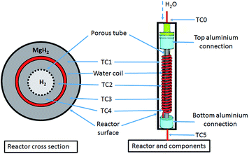 | ||
| Fig. 1 MH reactor with a stainless-steel coil embedded inside the MgH2 powder bed to transport a sc. H2O HTF. | ||
2.4 Optimisation of H2 desorption/absorption
36 g of the powder mixture (MgH2/TiB2/ENG) was manually compacted with a stainless steel rod at approximately 100 MPa of pressure whilst inside an argon glovebox (mBraun, Germany). Manual compaction was necessary due to the geometry of the internal water coil and sintered metal tube for H2 distribution. It was therefore impossible to manufacture pellets to conform to this specific geometry. The reactor was then attached to a prototype system, reported in a previous study,30 which consists of a 2 l volumetric gas store, after which the whole system was purged with H2 and left under 4 bar H2 pressure.To pump the HTF (H2O), the HTF coil was connected to a Gilson 305 piston pump that provides control over a wide range of flow rates (0.01 to 5.0 ml min−1) and pressures (1 bar to 600 bar). The water (MilliQ) was pressurised by the pump to 220 bar by using a back-pressure regulator, before being pre-heated to the desired inlet temperature by electrical heating tape before entering the reactor.
In addition, to compare the internal heating mode with the external heating mode, heating tape was also wrapped around the reactor to apply external heating when desired. In this case, the reactor's temperature was controlled by an Omron E5CN-H controller coupled with a K-type thermocouple placed on reactor's surface. Both the H2 pressure and temperatures within the reactor were recorded through a data acquisition device (OMB-DAQ-55, Omega) during H2 desorption/absorption.
2.5 Characterisation
After ∼20 thermally controlled hydrogen sorption cycles, the reactor was decommissioned, taken into the glovebox and cut open to investigate the sample's morphology within the reactor bed. Powder samples were collected from areas near the four thermocouples for analysis by using both powder X-ray diffraction (XRD) and scanning electron microscopy (SEM). XRD was performed using a Bruker D8 Advance diffractometer (CuKα radiation) utilising XRD sample holders covered with a poly(methylmethacrylate) (PMMA) airtight bubble to prevent oxygen/moisture contamination during data collection. The PMMA airtight bubble results in a broad hump in the XRD patterns centred at ∼20° 2θ. Data was acquired over a 2θ range of 20–80°, with a step size of 0.02° and count time of 1 s per step. The microstructure of the MH mixture, before and after cycling, was observed by SEM (Zeiss Neon 40EsB FE-SEM) using a custom-made sample holder in order to ensure that the samples were transported from the glove box to the SEM vacuum chamber under an Ar atmosphere.3. Results and discussion
3.1 Thermal conductivity
The thermal conductivity of a MgH2/TiB2/ENG pellet pressed at 223 MPa for 5 min and measured in the axial mode under 1 bar Ar was determined to be 1.77(5) W m−1 K−1. This value agrees well with the value obtained by Chaise et al. who measured a value of ∼1.6 W m−1 K−1 for a sample containing 10 wt% ENG pressed at 100 MPa and measured under 0.4 MPa H2.35 Although there is twice the quantity of ENG in the sample measured in this study (20 wt%), the ENG capacity does not significantly alter the thermal conductivity in the axial direction.36 On the other hand, for pellets pressed at 100 MPa in air and measured under 1 bar H2, the thermal conductivity was established to be 1.9 and 9 W m−1 K−1 for 10 wt% and 20 wt% ENG, respectively, measured in the radial direction.33 Thus a 20 wt% addition of ENG to MgH2 was deemed as optimal for this study. The thermal conductivity measured under 1 bar Ar is also expected to improve when measured in a hydrogen atmosphere especially under increased gas pressure (as expected during H2 desorption). At room temperature and 1 bar, Ar has a thermal conductivity of 0.018 W m−1 K−1,37 whereas H2 has a thermal conductivity of 0.182 W m−1 K−1 at 1 bar.38 It has been reported that an increase in H2 pressure from 1 to 20 bar results in an increase in pellet thermal conductivity from 9 to 13.4 W m−1 K−1, when measured in the radial direction (20 wt% ENG).33 This increase in conductivity at a higher pressure is largely attributed to the reduction of the mean free path between the H2 atoms (distance between the collision of two molecules), therefore the effective thermal conductivity of hydrogen is increased in the bed.39Although pellets have a higher thermal conductivity than powder, a previous study showed that MgH2/ENG pellets have very low mechanical strength for handling during assembly of the reactor and during cycling.30 To improve the interaction with the helical HTF tube the current study implements a powder bed. A hand pressed powder sample (MgH2/TiB2/ENG) was measured under an Ar atmosphere to have a thermal conductivity of 0.1337(6) W m−1 K−1. In general, it is understood that thermal conductivity increases with compaction40,41 and as such, the powder was manually compacted using approximately 100 MPa of pressure when loading the 36 g of powder into the reactor. Although the thermal conductivity of powder is lower than a pellet, the application of H2 pressure to the sample and the large contact area with the helical HTF coil should partially negate the adverse thermal properties due to a loss in thermal conductivity of the powder. In addition, in a highly compacted sample, the ENG becomes radially layered with thermal conductivity being preferential in that direction.35 As the powder sample is not compacted uniaxially inside the reactor, the orientation of the ENG will be more random, therefore enhancing heat transfer in an isotropic manner, rather than radially.
3.2 The effects of water flow rate on reactor temperatures
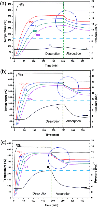
This study describes the optimisation of a prototype TES system that would be utilised in a concentrating solar thermal plant (CSP).12,14,30 The MH used in the reactor is MgH2, a material that is not only used in technological application as a hydrogen storage material, but has also been studied previously as a material for the TES.29,30,42–44 Due to the sintering of Mg at high temperature, the operating temperature of this material has been limited between 350 and 450 °C.29 In a previous study, the MgH2/TiB2/ENG mixture was loaded as pellets and the reactor was electrically heated externally using heating tape.30 Water was pumped at 350 bar through a straight stainless tube in the centre of the reactor in order to remove the thermal energy produced during hydrogen absorption. In the present study, the water HTF was preheated (450 °C for hydrogen desorption and 400 °C for absorption) and pumped at 220 bar as a supercritical (sc.) fluid prior to entering the reactor. In this manner, sc. H2O is being used as the HTF analogous to the molten salts that are used in current CSP plants.6 At the operating temperatures employed (372 °C, 220 bar) the density of the water is 465 kg m−3, thermal conductivity is 423 mW m−1 K−1 and specific heat capacity is 27.1 kJ kg−1 K−1.25 The heated water was passed through a stainless steel coil embedded in the powdered MH bed, as illustrated in Fig. 1, to achieve maximum contact with the MgH2 and promote homogeneous heating. This in turn provides a more consistent and uniform temperature to all of the material in the reactor compared to an external heating mode, benefiting reaction kinetics and increasing system efficiency.The flow rate of sc. H2O greatly affects the water temperature within the reactor, as well as prior and post reactor. If the flow is too slow, the water may cool too much before entering the reactor via thermal radiation loss through the stainless steel tubing. If the flow is too fast, the water does not have a long enough residence time and may not be heated or cooled enough before it exits the reactor. As such, the HTF flow rate was varied to optimise the operating conditions. Fig. 2 shows the temperature profiles of the reactor during the hydrogen desorption/absorption processes at HTF flow rates of 2, 3 and 4 ml min−1. During the first stage of the experiment, the inlet water temperature is set high (∼450 °C) so as to mimic the day cycle in a CSP plant. At this stage, the thermal energy (from the hypothetical sun) is being used to endothermically release hydrogen from MgH2 between 350 and 375 °C. As the water flow rate increases from 2 to 4 ml min−1, the water inlet temperature (position TC0 in Fig. 1) decreases from 460 °C to 425 °C, respectively, due to the reduced residence time inside the pre-heater. Although the HTF flow rate appears to be optimal at 2 ml min−1 in terms of a water temperature (TC0) of 461 °C, there is a large spread in temperatures throughout the reactor bed (over 100 °C between TC1–TC4). The temperature gradient is due to rapid HTF heat loss to the upper parts of the reactor, and to radiant heat loss, before the HTF can reach the lower parts of the reactor. This scenario means that H2 is only released from MgH2 near TC1 as the temperature dependent H2 equilibrium pressure associated with MgH2 at TC2, TC3 and TC4 is below the hydrogen pressure in the system and desorption does not proceed.
Obviously, the HTF flow rate greatly affects temperatures throughout the reactor. As the flow rate is increased, the average temperature of the reactor is increased as more heat is delivered than is lost radiantly. This means that the entire reactor requires less time to reach the desired operating temperature for hydrogen release. Effectively, this scenario is the result of an optimal heat flow rate to the reactor, based on its heat transfer characteristics. At a water flow rate of 4 ml min−1, there is a minimal temperature difference between TC1–TC4. The uniform temperature ensures that the MgH2 within the reactor is able to release hydrogen consistently across the reactor bed, so as to maximise the reactor's heat storage capacity. Therefore, the reactor can be uniformly heated by the HTF with the internal heating mode (IHM) under these conditions.
To mimic the night cycle in CSP applications, the inlet temperature of the system was decreased to 375 °C. This invoked a temperature decrease of the powder bed, lowering the equilibrium pressure, and promoting hydrogen absorption. It can be seen in Fig. 2 that the temperature at T0 decreases rapidly while the temperature at T1–T4 decreases slowly. This is the result of the exothermic absorption process taking place, triggering self-heating within the powder bed. The quantity of heat produced will not rise above that allowed by the thermodynamic properties of MgH2 (which govern the equilibrium pressure and thus determine when the material can absorb hydrogen) and so a temperature plateau is expected. Due to the large radiative heat loss of the system and relatively small quantity of sample, a rather small thermal plateau is observed. The radiative heat loss from T0 to T1 leads to the requirement of higher temperatures at T0 to reach the operating temperatures required by the powder.
The hydrogen capacity of the system is dependent on the water flow rate of the system as this directly affects the system temperature and, hence, the hydrogen equilibrium pressure that is generated. For this MgH2 system (29 g of MgH2 excluding ENG and TiB2 additives) desorbing hydrogen at an operating temperature of 375 °C into a ∼2.5 l system volume a maximum gas pressure of ∼13 bar is possible based on the quantity of hydrogen present. According to the thermodynamics of MgH2 (ΔHdes = 74.06 kJ mol−1; ΔSdes = 133.4 J K−1 mol−1 H2) the equilibrium pressure of desorption is 10 bar.44 Therefore, at a water flow rate of 4 ml min−1, full desorption is not achievable as the equilibrium pressure of the MgH2 (10 bar) has been reached before all hydrogen is released. To achieve full desorption, a higher temperature or a larger system volume is required. For lower water flow rates, full hydrogen desorption is also not achieved with only 8 bar and 4 bar of hydrogen system pressure being produced at 3 ml min−1 and 4 ml min−1 water flow rates; respectively. This is attributed to the inhomogeneity of heat through the reactor causing a large distribution of reacted fractions throughout the powder bed. However, it can be seen that full rehydrogenation is achieved at each water flow rate condition as the hydrogen pressure returns to the original pressure of ∼3 bar indicating no loss of capacity.
3.3 Comparison of the internal and external heating modes
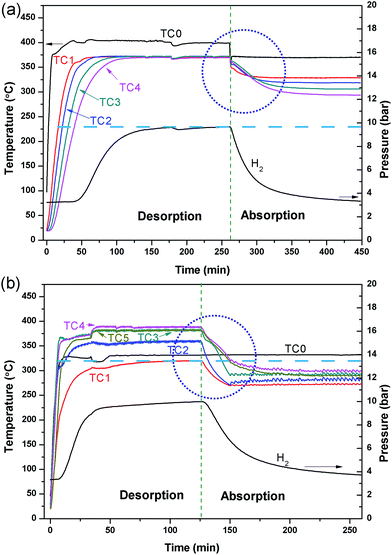
A comparative test was undertaken to compare the efficiency of hydrogen sorption processes initiated by the internal HTF heating mode (IHM) and the external HTF heating mode (EHM). For the EHM, heat was applied by a heating tape tightly wrapped around the reactor, set to 415 °C. At the same time, the internal HTF was preheated to 330 °C before entering the reactor to ensure that the temperatures required for desorption/absorption were achieved within the reactor. A HTF flow rate of 5 ml min−1 was used for both systems, which is the maximum flow rate of the pump. Fig. 3 illustrates the temperature profiles of the reactor operated with the IHM and EHM. The IHM produces a uniform temperature (372 °C) throughout the reactor with a minimal temperature gradient, while the EHM produces a large temperature gradient from the top (320 °C) to the bottom (390 °C) of the reactor due to the coupled contribution from the HTF and the external heating tape.The large temperature difference in the EHM can ultimately cause incomplete hydrogen desorption from colder regions of the reactor and therefore can reduce the total heat storage capacity of the system. As the equilibrium pressure of hydrogen desorption is strongly affected by temperature, desorption of H2 will be inhibited when the temperature of the MgH2 bed falls below the point where its thermodynamic equilibrium pressure falls below the system's gas pressure. For instance, at 390 °C the equilibrium pressure of desorption for MgH2 is 13.6 bar while at 320 °C the equilibrium pressure is 2.8 bar.44 If the hydrogen gas pressure in the system is above the equilibrium pressure (i.e. 2.8 bar), desorption will be halted at that part of the reactor and hydrogen absorption may even occur.
The large temperature difference within the reactor during the EHM is likely caused by two reasons: the internal HTF (330 °C) cools the reactor as it flows through the bed from top to bottom, resulting in a temperature gradient; and/or, as the reactor is heated externally, a thermal gradient could be caused by inhomogeneous heating or inhomogeneous radiant heat loss, especially axially to the reactor. To investigate the situation, the HTF was not initially applied while heating the exterior of the reactor (Fig. 4). A temperature gradient in the reactor was still observed with TC1 and TC4 (at either ends of the reactor), showing lower temperatures at the ends than at the centre of the reactor (TC2 and TC3). This may be attributed to the lower density of insulation at the ends of the reactor than in the middle. After 75 min, the HTF pump was started with pre-heating set to 375 °C. Initially, the HTF flowing through the reactor is colder than the EHM set point and colder than most of the reactor, thus a temperature decrease inside the top of the reactor (TC1 and TC2) is observed. On the contrary, the temperature at TC4 increased. Overall, by the time TC0 reaches the 375 °C set point the EHM set point is adjusted to 300 °C and hydrogen absorption occurs. There is an increase in the thermal gradient on HTF flow that confirms the HTF is principally responsible for preferentially cooling the top of the reactor and greatly contributes to the temperature difference observed during the EHM tests.
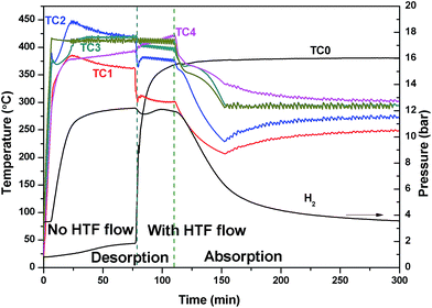 | ||
| Fig. 4 Reactor temperature and H2 pressure profile initially with no HTF flow, which is then pumped a flow rate of 2 ml min−1 after 75 min whilst using the external heating mode. | ||
The linear flow rate of water through the 1.59 mm tubing in the reactor bed is 32 cm s−1 at a flow rate of 5 ml min−1, and it only takes 5 s for the water to pass through the reactor. The rapid water flow does not allow the HTF to excessively cool/heat in the reactor bed when operating with the IHM, extracting/imparting thermal energy in a uniform fashion from top to bottom. Although, the heat transfer initially dominates at the top of the reactor, as shown in Fig. 3a, the heating rapidly becomes uniform throughout the reactor, resulting in a constant bed temperature without an axial thermal gradient.
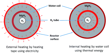
Disregarding the temperature homogeneity within the system, it appears that the IHM and EHM are comparable. Both IHM and EHM systems desorb hydrogen in equal quantities, to the equilibrium pressure of 10 bar (for an operating temperature of 375 °C). In fact, the EHM reaches equilibrium within 40 min, whereas the IHM requires 120 min. It is not correct to directly compare the systems in terms of their kinetic performance because the IHM and EHM do not apply the same heating power. The heating tape in EHM is able to provide 750 W of heating, while the only 50 W can be provided by the sc. H2O during IHM.30 The IHM uses a single heat source, mimicking a full-scale CSP heat storage system, resulting in a uniform temperature distribution within the reactor. For the EHM, the heating tape is on the outside of the reactor where considerable heat escapes to the environment, even though the reactor is heavily insulated. In addition, the water is being preheated to 325 °C. As shown in Fig. 5, there is a significant amount of heat loss to the environment when using the EHM. The water coil provides a closer contact with powder, resulting in a short heat transfer distance. This greatly improves heating efficiency compared with the external heating system.
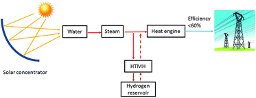
During the H2 sorption processes, H2 diffuses from/to the centre of the reactor, and therefore the sorption process occurs more effectively near the centre of the reactor where hydrogen can easily diffuse. The internal water coil can heat the central region more effectively compared to the EHM, which heats from the outside of the reactor first. In addition, the IHM effectively illustrates how the TES material would be heated in a practical application, such as in a CSP plant. The TES material could be directly heated via superheated steam generated by the solar thermal concentrator.24 As shown in Fig. 6, superheated steam may be used as the HTF to transfer solar thermal energy to the MH thermal energy store (which will endothermically release hydrogen gas). At night, or during intermittent periods of solar irradiance, the reactor cools until exothermic hydrogen absorption in the residual metal (i.e. Mg) generates heat, which would be directly transferred to the HTF, producing electricity at the heat engine.
Overall, the IHM requires a longer time to reach the desired hydrogen absorption temperature (∼372 °C) than the EHM.
Ultimately, the heating rate of the reactor (IHM) is essentially controlled by both the water flow rate and the temperature of the preheated water. The time required to heat the reactor could be reduced by increasing the flow rate of the water and/or the water temperature.
3.4 Post-cyclic analysis
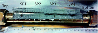
After thermal testing, the MgH2 reactor was disconnected from the gas system while in the hydrogenated state and opened to investigate the powder bed. In the glove box, slots were cut through the reactor's surface using a rotary tool, as shown in Fig. 7. There is no macroscopic agglomeration (sintered material) or noticeable void formation after ∼20 cycles,45 indicating that uniform sorption reactions occurred within the reactor. Powder samples were collected from various positions in the reactor (SP1, SP2, SP3 and SP4 labelled in Fig. 7) close to the thermocouple positions for XRD and SEM observation. XRD patterns for these samples are illustrated in Fig. 8. After hydrogen cycling diffraction peaks from Mg are also present in some regions of the reactor in addition to MgH2. The samples in the middle of the reactor (SP2 and SP3) show more Mg compared to the samples near the two ends (SP1 and SP4). This demonstrates that hydrogen absorption first occurs at the ends of the reactor due to preferential cooling to the environment which promotes the onset of hydrogenation to occur before the warmer areas.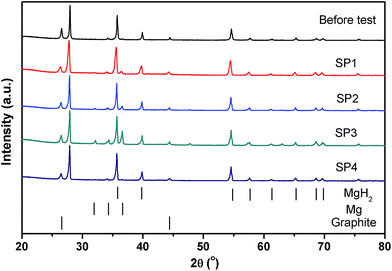 | ||
| Fig. 8 XRD patterns of powder samples before and after cycling at the different axial positions in the reactor. | ||
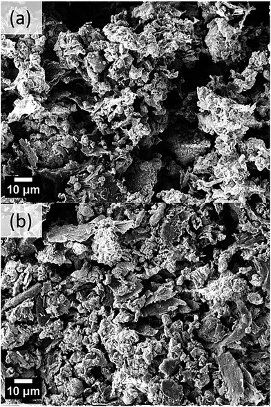
Fig. 9 shows SEM micrographs of the MgH2/TiB2/ENG mixture before and after thermal cycling. The samples after cycling (Fig. 9b) are more compact, which is likely due to the process of packing the sample within the reactor and hydrogen gas pressure during cycling. There is no obvious difference in packing the sample within the reactor and hydrogen gas pressure during cycling. There is no obvious difference in sample morphology from the top of the reactor to the bottom of the reactor, and no macroscopic particle agglomeration is observed.
4. Conclusions
Thermal energy storage materials are required to store excess energy to solve the intermittency problem of solar energy in CSP plants. In this study, a TES system based on MgH2 has been designed, constructed and optimised, improving on previously reported TES systems. The implementation of internal heating of the MH using a heat transfer fluid, in this case sc. H2O, allows for a uniform temperature distribution throughout the reactor compared to external heating of the reactor. A uniform temperature distribution allows for complete hydrogen sorption cycles, improving thermal efficiency of the system and preventing sample degradation.Powder X-ray diffraction and scanning electron microscopy of sampled after ∼20 cycles showed that no significant degradation of the sample occurred, which will allow for long term cycling of this material.
By optimising the design and operating conditions of this MH-TES system, an efficient energy storage system can be realised. The problem of heat transfer through the powder bed becomes more of an issue as the reactor is scaled up, but radiant heat losses are reduced.
Conflicts of interest
There are no conflicts to declare.Acknowledgements
CEB, DAS and MP acknowledge the financial support of the Australian Research Council (ARC) for ARC Linkage grants LP120101848 and LP150100730, and CEB acknowledges the financial support of the ARC LIEF grant LE0775551, which enabled the XRD measurements to be undertaken. DAS acknowledges the financial support of a Curtin University Postdoctoral Research Fellowship. The authors also thank the John De Laeter Centre for the SEM analysis and also the Australia-Germany Joint Research Cooperation Scheme (DAAD, project 57218310) for financial support.References
- D. Abbott, Proc. IEEE, 2009, 97, 1931–1934 CrossRef.
- I. Purohit and P. Purohit, Renewable Sustainable Energy Rev., 2017, 78, 648–667 CrossRef.
- REN21, Renewables 2016 Global Status Report, http://www.ren21.net/wp-content/uploads/2016/05/GSR_2016_Full_Report_lowres.pdf, accessed 16 June 2017 Search PubMed.
- D. N. Harries, M. Paskevicius, D. A. Sheppard, T. Price and C. E. Buckley, Proc. IEEE, 2012, 100, 539–549 CrossRef CAS.
- NREL, Ivanpah Solar Electric Generating System, https://www.nrel.gov/csp/solarpaces/project_detail.cfm/projectID=62, accessed 08/05/2017 Search PubMed.
- U. S. Department of Energy, Report – “Sunshot Vision Study”, 2012, http://energy.gov/eere/sunshot/downloads/sunshot-vision-study-february-2012-book-sunshot-energy-efficiency-renewable, accessed 08/05/2017 Search PubMed.
- NREL, Concentrating Solar Power Projects – Crescent Dunes Solar Energy Project, http://www.nrel.gov/csp/solarpaces/project_detail.cfm/projectID=60, accessed 08/05/2017 Search PubMed.
- W. Gardner, R. McNaughton, J. Kim and S. Barrett, Development of a solar thermal supercritical steam generator, in Proceedings of the 50th Annual Conference of the Australian Solar Energy Society, Melbourne, 2012 Search PubMed.
- CSIRO, Case study: Supercritical steam, https://www.csiro.au/en/Research/EF/Areas/Solar/Solar-thermal/Supercritical-steam, accessed 16 June 2017 Search PubMed.
- D. A. Sheppard, T. D. Humphries and C. E. Buckley, Appl. Phys. A, 2016, 122, 406 CrossRef.
- IRENA, Renewable Energy Technologies: Cost Analysis Series. Volume 1: Power Sector. Issue 2/5, https://www.irena.org/documentdownloads/publications/re_technologies_cost_analysis-csp.pdf, accessed 08/05/2017 Search PubMed.
- D. A. Sheppard, M. Paskevicius, T. D. Humphries, M. Felderhoff, G. Capurso, J. Bellosta von Colbe, M. Dornheim, T. Klassen, P. A. Ward, J. A. Teprovich, C. Corgnale, R. Zidan, D. M. Grant and C. E. Buckley, Appl. Phys. A, 2016, 122, 395 CrossRef.
- T. D. Humphries, D. A. Sheppard, M. R. Rowles, M. V. Sofianos and C. E. Buckley, J. Mater. Chem. A, 2016, 4, 12170–12178 CAS.
- D. A. Sheppard, T. D. Humphries and C. E. Buckley, Mater. Today, 2015, 18, 414–415 CrossRef.
- T. D. Humphries, D. A. Sheppard and C. E. Buckley, Coord. Chem. Rev., 2017, 342, 19–33 CrossRef CAS.
- C. N. Ranong, M. Hohne, J. Franzen, J. Hapke, G. Fieg, M. Dornheim, N. Eigen, J. M. B. von Colbe and O. Metz, Chem. Eng. Technol., 2009, 32, 1154–1163 CrossRef.
- M. V. Lototskyy, V. A. Yartys, B. G. Pollet and R. C. Bowman, Int. J. Hydrogen Energy, 2014, 39, 5818–5851 CrossRef CAS.
- A. Mazzucco, M. Dornheim, M. Sloth, T. R. Jensen, J. O. Jensen and M. Rokni, Int. J. Hydrogen Energy, 2014, 39, 17054–17074 CrossRef CAS.
- US Department of Energy, SunShot Vision Study, Chapter 5: Concentrating Solar Power: Technologies, Cost, and Performance, US Department of Energy, 2012 Search PubMed.
- C. Corgnale, B. Hardy, T. Motyka, R. Zidan, J. Teprovich and B. Peters, Renewable Sustainable Energy Rev., 2014, 38, 821–833 CrossRef CAS.
- P. A. Ward, C. Corgnale, J. A. Teprovich, T. Motyka, B. Hardy, D. Sheppard, C. Buckley and R. Zidan, Appl. Phys. A, 2016, 122, 462 CrossRef.
- D. A. Sheppard, C. Corgnale, B. Hardy, T. Motyka, R. Zidan, M. Paskevicius and C. E. Buckley, RSC Adv., 2014, 4, 26552–26562 RSC.
- R. Urbanczyk, K. Peinecke, S. Peil and M. Felderhoff, Int. J. Hydrogen Energy, 2017, 42, 13818–13826 CrossRef CAS.
- K. Vignarooban, X. Xu, A. Arvay, K. Hsu and A. M. Kannan, Appl. Energy, 2015, 146, 383–396 CrossRef CAS.
- E. W. Lemmon, M. O. McLinden and D. G. Friend, “Thermophysical Properties of Fluid Systems” in NIST Chemistry WebBook, NIST Standard Reference Database Number 69, http://webbook.nist.gov, accessed 04/08/2017 Search PubMed.
- G. Sandrock, S. Suda and L. Schlapbach, in Hydrogen in Intermetallic Compounds II, Surface and Dynamic Properties, Applications, ed. L. Schlapbach, Springer-Verlag, Berlin Heidelberg, 1992, vol. 67, ch. 5, pp. 197–258 Search PubMed.
- Z. W. Bao, Int. J. Hydrogen Energy, 2015, 40, 5664–5676 CrossRef CAS.
- A. Souahlia, H. Dhaou, F. Askri, M. Sofiene, A. Jemni and S. Ben Nasrallah, Int. J. Hydrogen Energy, 2011, 36, 12918–12922 CrossRef CAS.
- B. Bogdanović, A. Ritter, B. Spliethoff and K. Straβburger, Int. J. Hydrogen Energy, 1995, 20, 811–822 CrossRef.
- M. Paskevicius, D. A. Sheppard, K. Williamson and C. E. Buckley, Energy, 2015, 88, 469–477 CrossRef CAS.
- B. Delhomme, P. de Rango, P. Marty, M. Bacia, B. Zawilski, C. Raufast, S. Miraglia and D. Fruchart, Int. J. Hydrogen Energy, 2012, 37, 9103–9111 CrossRef CAS.
- M. Y. Yan, F. Sun, X. P. Liu, J. H. Ye, H. P. Yuan, S. M. Wang and L. J. Jiang, J. Alloys Compd., 2014, 603, 19–22 CrossRef CAS.
- J.-H. Shim, M. Park, Y. H. Lee, S. Kim, Y. H. Im, J.-Y. Suh and Y. W. Cho, Int. J. Hydrogen Energy, 2014, 39, 349–355 CrossRef CAS.
- S. Mellouli, F. Askri, H. Dhaou, A. Jemni and S. Ben Nasrallah, Int. J. Hydrogen Energy, 2007, 32, 3501–3507 CrossRef CAS.
- A. Chaise, P. de Rango, P. Marty, D. Fruchart, S. Miraglia, R. Olivès and S. Garrier, Int. J. Hydrogen Energy, 2009, 34, 8589–8596 CrossRef CAS.
- C. Pohlmann, L. Röntzsch, S. Kalinichenka, T. Hutsch and B. Kieback, Int. J. Hydrogen Energy, 2010, 35, 12829–12836 CrossRef CAS.
- B. S. Sheppard, W.-L. Shen, T. M. Davidson and J. A. Caruso, J. Anal. At. Spectrom., 1990, 5, 697–700 RSC.
- E. Suissa, I. Jacob and Z. Hadari, J. Less-Common Met., 1984, 104, 287–295 CrossRef CAS.
- J. Kapischke and J. Hapke, Exp. Therm. Fluid Sci., 1994, 9, 337–344 CrossRef CAS.
- A. Mills, M. Farid, J. R. Selman and S. Al-Hallaj, Appl. Therm. Eng., 2006, 26, 1652–1661 CrossRef CAS.
- G. A. Lozano, C. N. Ranong, J. M. Bellosta von Colbe, R. Bormann, J. Hapke, G. Fieg, T. Klassen and M. Dornheim, Int. J. Hydrogen Energy, 2012, 37, 2825–2834 CrossRef CAS.
- J.-C. Crivello, R. V. Denys, M. Dornheim, M. Felderhoff, D. M. Grant, J. Huot, T. R. Jensen, P. de Jongh, M. Latroche, G. S. Walker, C. J. Webb and V. A. Yartys, Appl. Phys. A, 2016, 122, 85 CrossRef.
- Q. Lai, M. Paskevicius, D. A. Sheppard, C. E. Buckley, A. W. Thornton, M. R. Hill, Q. Gu, J. Mao, Z. Huang, H. K. Liu, Z. Guo, A. Banerjee, S. Chakraborty, R. Ahuja and K.-F. Aguey-Zinsou, ChemSusChem, 2015, 8, 2789–2825 CrossRef CAS PubMed.
- M. Paskevicius, D. A. Sheppard and C. E. Buckley, J. Am. Chem. Soc., 2010, 132, 5077–5083 CrossRef CAS PubMed.
- R. Urbanczyk, M. Meggouh, R. Moury, K. Peinecke, S. Peil and M. Felderhoff, Appl. Phys. A: Mater. Sci. Process., 2016, 122, 315 CrossRef.
| This journal is © The Royal Society of Chemistry 2017 |

