 Open Access Article
Four-step iron(II) spin state cascade driven by antagonistic solid state interactions†
Natasha F.
Sciortino
a,
Katrina A.
Zenere
a,
Maggie E.
Corrigan
a,
Gregory J.
Halder
b,
Guillaume
Chastanet
c,
Jean-François
Létard
c,
Cameron J.
Kepert
*a and
Suzanne M.
Neville
*a
aSchool of Chemistry, The University of Sydney, NSW 2006, Australia. E-mail: suzanne.neville@sydney.edu.au; Tel: +61-2-9351-7791
bX-ray Science Division, Advanced Photon Source, Argonne National Laboratory, IL 60439, USA
cCNRS, Univ. Bordeaux, ICMCB, UPR 9048, F-33600, Pessac, France
First published on 12th September 2016
Abstract
A four-stepped cascade of Fe(II) high spin (HS) to low spin (LS) states is demonstrated in a family of 2-D Hofmann materials, [Fe3II(saltrz)6(MII(CN)4)3]·8(H2O) (MII = Pd (1Pd), Pt (1Pt); saltrz = (E)-2-(((4H-1,2,4-triazol-4-yl)imino)methyl)phenol). Alongside the fully HS and LS Fe(II) states, fractional spin state stabilization occurs at HS/LS values of 5/6, 2/3, and 1/6. This unconventional spin state periodicity is driven by the presence of multiple spin crossover (SCO) active Fe(II) sites which are in subtly distinct environments driven by a network of antagonistic host–host and host–guest interactions. Alternating long- and short-range magnetostructural ordering is achieved over the five distinct spin state ratios HS1.0LS0.0, HS0.833LS0.167, HS0.667LS0.333, HS0.167LS0.833, and HS0.0LS1.0 owing to the flexibility of this 2-D interdigitated lattice topology interconnected by intermolecular interactions. A distinct wave-like spin state patterning is structurally evidenced for each intermediate phase.
Introduction
An alluring aspect of the spin crossover (SCO) phenomenon is its representation of an electronic switch, whereby two distinct magnetic states (high spin (HS) and low spin (LS)) are accessed through variations in environmental factors such as temperature, pressure and light-irradiation.1–9 The dynamic conversion between these states provides a multitude of physical, chemical and electronic variations with which to target potential applications in the data storage and display device arenas.2,3,10An intriguing characteristic of the SCO effect is the cohort of short- and long-range lattice effects which enable solid state cooperativity, reflected by hysteretic and multi-stepped spin transitions.10,11 Multi-stepped spin transitions arise from competing “ferro- and “antiferro-elastic-like interactions and are pursued both fundamentally and with an interest in exploring their novel electronic functionalities for applications such as in ternary and higher-order information storage. In that sense, elastic frustration is of primordial importance to induce multi-stepped character.12
Among multi-stepped transitions, those of two-step character are the most prevalent in the literature and can be realised through the presence of numerous crystallographically distinct SCO-active sites (i.e. [HS–HS] ↔ [HS–LS] ↔ [LS–LS]), a single site with short-range or lower dimensional ordering (i.e. [HS] ↔ [HS/LS] ↔ [LS]),13–17 or long-range ordering, in which a mid-temperature phase transition leads to a distinction between previously equivalent sites (i.e. [HS] ↔ [HS–LS] ↔ [LS]).18–23 Spin transitions proceeding via three or more steps are extremely uncommon24–27 and many examples are poorly structurally characterised compared to two-step materials. The fractional changes in multi-stepped transitions intrinsically require that more complex arrangements of SCO centres establish structural ordering, with the mismatch in coordination bond distances for the LS and HS states imparting significant lattice strain. Notable multi-step examples include the 3-D Hofmann material [Fe(dpsme)Pt(CN)4]·(guest)25 (dpsme = 4,4′-di(pyridylthio)methane), which shows formal tristability at fixed temperatures due to overlapping thermal hysteresis of the multi-step transitions and, more recently, an incomplete Devil's staircase-like transition in a 2-D coordination polymer,26 and a four-step transition in a Hofmann-like phase.27 In this article, we present a rare four-stepped transition in a family of 2-D Hofmann-type materials which is enabled by a synergy between covalent lattice cooperativity and a network of antagonistic host–host and host–guest interactions. Using the elastic frustration present in the [FePt(CN)4] planes,12 combined with axial monodentate ligands able to generate weak interactions between each other or with inserted guest molecules, multiple symmetry breaking alongside spin crossover has been achieved.13,28,29 The flexibility of the 2-D lattice, combined with the array of interactions, allows the lattice to accommodate five distinct spin state profiles upon temperature variation. The fractional HS and LS states stabilised here are uniquely related to sixths and present an additional advance toward the theoretical Devil's staircase concept which was recently highlighted for SCO systems to describe the series of steps possible in multi-stepped transitions.26
Results and discussion
Overall structure
Single crystal diffraction data were collected on 1Pd and 1Pt at 240 K, representative of the HS Fe(II) state, and revealed isostructural materials; henceforth, the structure of 1Pt will be discussed (Tables S1 and S2†). Overall, the asymmetric unit consists of two unique Fe(II) sites (½Fe1![[thin space (1/6-em)]](https://www.rsc.org/images/entities/char_2009.gif) :
:![[thin space (1/6-em)]](https://www.rsc.org/images/entities/char_2009.gif) 1Fe2; the ½
1Fe2; the ½![[thin space (1/6-em)]](https://www.rsc.org/images/entities/char_2009.gif) :
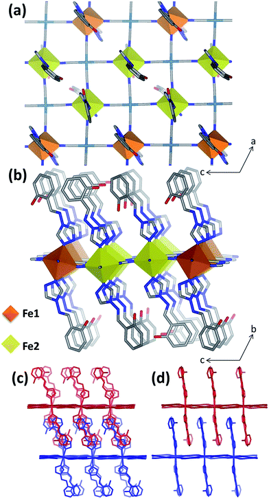
:![[thin space (1/6-em)]](https://www.rsc.org/images/entities/char_2009.gif) 1 ratio arises due to the former lying on an inversion centre whereas the latter is on a general position), one and a half [Pt(CN)4]2− groups, three unique saltrz ligands, and four water molecules (Fig. S4†), thus giving an overall formula of [Fe3II(saltrz)6(PtII(CN)4)3]·8(H2O). The distorted octahedral Fe(II) centres are each comprised of four equatorially coordinated [Pt(CN)4]2− metallo-ligands bound through the N-atoms and two axially coordinated N-donor terminal saltrz ligands; this is typical of Hofmann materials. Two-dimensional Hofmann layers of composition [FeIIPt(CN)4] are thus generated through the bridging of Fe(II) sites by four coordinating [Pt(CN)4]2− units (Fig. 1(a)), with the octahedral Fe(II) geometry completed axially by bound saltrz ligands (coordinated through N1 of the triazole ring), which protrude above and below the Hofmann layer (Fig. 1(b)). These 2-D layers pack efficiently through the inter-digitation of saltrz ligands from neighbouring layers. A 2-D network is produced with sufficient pore area in the interlayer spacing to accommodate solvent water molecules (Fig. 1(c and d) and 2).
1 ratio arises due to the former lying on an inversion centre whereas the latter is on a general position), one and a half [Pt(CN)4]2− groups, three unique saltrz ligands, and four water molecules (Fig. S4†), thus giving an overall formula of [Fe3II(saltrz)6(PtII(CN)4)3]·8(H2O). The distorted octahedral Fe(II) centres are each comprised of four equatorially coordinated [Pt(CN)4]2− metallo-ligands bound through the N-atoms and two axially coordinated N-donor terminal saltrz ligands; this is typical of Hofmann materials. Two-dimensional Hofmann layers of composition [FeIIPt(CN)4] are thus generated through the bridging of Fe(II) sites by four coordinating [Pt(CN)4]2− units (Fig. 1(a)), with the octahedral Fe(II) geometry completed axially by bound saltrz ligands (coordinated through N1 of the triazole ring), which protrude above and below the Hofmann layer (Fig. 1(b)). These 2-D layers pack efficiently through the inter-digitation of saltrz ligands from neighbouring layers. A 2-D network is produced with sufficient pore area in the interlayer spacing to accommodate solvent water molecules (Fig. 1(c and d) and 2).
A significant driving force for the distinction of Fe1 and Fe2 sites is an extensive network of host–host and host–guest hydrogen-bonding interactions facilitated by the saltrz hydroxyl groups. This array of interactions confers significant intra-Hofmann layer ([FeIIM(CN)4]) distortions and a variety of ligand orientations. In particular, the 2-D [FeIIM(CN)4] layers, which lie approximately in the ac-plane, show a wave-like undulation highlighted by the relative tilt angle of the Fe(II) octahedron out of the plane and the significant deviation of the Fe–N![[triple bond, length as m-dash]](https://www.rsc.org/images/entities/char_e002.gif) C angles from 180° (Table S3† and Fig. 1(b)). This quantification highlights a major distinction between Fe1 and Fe2 sites, whereby the Fe1 octahedra are more tilted than the Fe2 octahedra (i.e., Fe1–N
C angles from 180° (Table S3† and Fig. 1(b)). This quantification highlights a major distinction between Fe1 and Fe2 sites, whereby the Fe1 octahedra are more tilted than the Fe2 octahedra (i.e., Fe1–N![[triple bond, length as m-dash]](https://www.rsc.org/images/entities/char_e002.gif) C angles show substantially more deviation from linearity) with respect to a perfectly planar Hofmann layer. Notably, within each 2-D [FeIIM(CN)4] layer the Fe1 and Fe2 sites are distributed in stripes along the a-axis with double ribbons of Fe2 sites separated by single ribbons of Fe1 (Fig. 1(a and b)).
C angles show substantially more deviation from linearity) with respect to a perfectly planar Hofmann layer. Notably, within each 2-D [FeIIM(CN)4] layer the Fe1 and Fe2 sites are distributed in stripes along the a-axis with double ribbons of Fe2 sites separated by single ribbons of Fe1 (Fig. 1(a and b)).
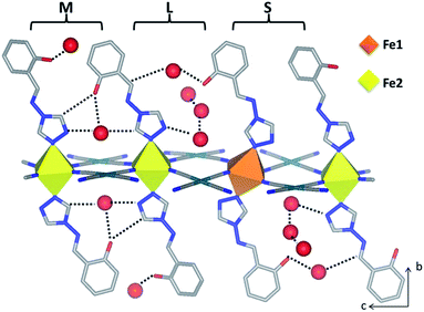
Of further structural note in distinguishing Fe1 and Fe2, the three crystallographically unique saltrz ligands differ significantly in their geometry and relative interlayer disposition. In particular, the two possible conformations of the appended hydroxyl groups of the saltrz ligands (cis- and trans- with respect to the bound 1,2,4-triazole nitrogen) are distinctly represented, such that Fe1 is bound to two cis-saltrz ligands and Fe2 is bound to one cis- and one trans-saltrz ligand (Fig. 2). Further distinguishing these ligands is a range of Fe–N–N(trz) ‘bite’ angles, driven by varying host–host and host–guest interactions (Fig. 2).
Overall, the combination of different octahedral tilt angles of Fe1 and Fe2, respective Fe–N–N(trz) ‘bite angles’ and cis/trans-conformations results in various ligand ‘tilting’ within the interlayer spacing (Table S3† and Fig. 2). The most significant consequence of this is the presence of three different spacings between adjacent ligands along the c-axis, labeled as small (S), medium (M) and large (L) in Fig. 2. Within these ligand pair spacings two, one or zero hydroxyl groups protrude. The smaller region (S), despite having ligands in close proximity, does not display any hydrogen-bonding interactions and, additionally, does not contain any guest water molecules. The medium region (M) contains both host–host and host–guest interactions. The largest region (L) shows numerous host–guest interactions and host–host interactions in the form of a 1-D chain of water molecules along the a-direction. This complex array of host–host, host–guest and guest–guest interactions is depicted in Fig. 2 and summarised in Table S5.†
Magnetic susceptibility
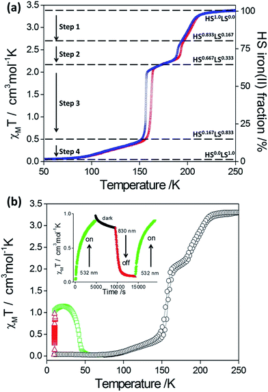
Both 1Pd and 1Pt show abrupt and hysteretic four-step SCO character (Fig. 3). Focusing firstly on 1Pt (Fig. 3(a)), with cooling from room temperature, the χMT values remain constant at ca. 3.38 cm3 mol−1 K, indicating that all Fe(II) sites are in the HS state. Over the range 215–190 K, a decrease in χMT values is observed followed by a more rapid decrease over the range 190 to 185 K. The step in this region corresponds to a conversion of one-sixth of the HS Fe(II) sites (i.e. a resultant 5/6 HS fraction). A plateau with a subtle slope exists over the range 185–160 K. The centre of this plateau region (χMT = 2.12 cm3 mol−1 K) represents a conversion of a further one-sixth of the Fe(II) HS sites to the LS state (i.e., overall a 2/3 HS fraction). Over the range 160–150 K the χMT values decrease very rapidly with the χMT values at 150 K corresponding to one half of the remaining HS Fe(II) sites converting to the LS state (i.e., 1/6 HS sites remaining). Below 150 K there is a gradual decrease in χMT values such that all of the Fe(II) sites are in the LS state at temperatures below 90 K (i.e., 0/6 HS fraction). The warming curve shows the same four-step SCO behaviour with hysteresis loops present in the second and third steps (Step 1: T½↓↑: 200, 202 K; Step 2: T½↓↑: 190, 194 K; Step 3: T½↓↑: 156, 162 K; Step 4: T½: 104 K).Complex 1Pd, which also displays four-step SCO behaviour, was assessed for photo-excitation properties by irradiating a thin layer of crystals at 10 K (λ = 510 nm, Fig. 3(b)). A degree of photo-excitation of the LS species to a metastable HS state was observed, with the χMT product reaching saturation at 1.2 cm3 mol−1 K. This indicates a photo-excitation efficiency of around 30%. The photoactivity process is readily cycled ‘on’ and ‘off’ at 10 K with alternating irradiation at wavelengths of 510 nm (LIESST effect) and 830 nm (reverse-LIESST effect) (Fig. 3b (inset)). The T(LIESST) value for 1Pd (42 K) is consistent with other 2-D framework materials containing flexible uni-dentate ligands (Fig. S7†).25,29–31 It would be of interest to investigate via structural methods if the non-quantitative photo-conversion is related to multi-stepped SCO behaviour, whereby a stoichiometric 2/6 HS fraction step, which was bypassed in the thermal SCO for the bulk sample, could be accessed by irradiation, or whether it is related to the strong competition between relaxation and excitation in this low temperature region.
Variable temperature synchrotron powder X-ray diffraction
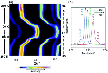
As an initial overview of the evolution of the bulk structure versus temperature, powder X-ray diffraction analysis was carried out on 1Pt using synchrotron radiation (280–100 K). The overall thermal dependence of the peak positions reflects a four-step SCO transition (Fig. 4(a)). Fine analysis of individual patterns reveals the emergence of additional Bragg peaks over the distinct temperature range 195–150 K, indicative of a phase transition. Fig. 4(b) highlights the region 2θ = 7–7.5° where additional reflections (e.g. (1 −1 −2)) are present at 250 and 100 K, but absent at intermediate temperatures (e.g. 170 K). Thus a different crystallographic phase exists over the temperature regions encompassing Steps 2 and 3 (Fig. 3(a)). This re-entrant behaviour occurs such that the high and low temperature regions display the same unit cell and symmetry separated by a unique ‘intermediate’ phase.18 Le Bail analysis of individual patterns (performed using the parent cell parameters) was carried out and maps the thermal dependence of the magnetic susceptibility precisely (Fig. S6†), thus confirming the bulk structure–function behaviour.Variable temperature single crystal data analysis
In order to correlate the rare four-step SCO behaviour with structural features and the unusual plateau points (i.e. at sixths instead of quarters), variable temperature single crystal data were collected at each plateau region in the magnetic data (Table S1†). The following structural analysis is focused on the 1Pt analogue.With cooling over the range 240 to 195 K, the same crystal symmetry and approximate cell parameters are observed representative of the ‘parent cell’. Complete structural analysis at 240 K reveals average Fe–N bond lengths consistent with both Fe(II) sites being in the HS state (Table S3†). At this temperature there are two Fe(II) sites, Fe1 and Fe2 present in a 1![[thin space (1/6-em)]](https://www.rsc.org/images/entities/char_2009.gif) :
:![[thin space (1/6-em)]](https://www.rsc.org/images/entities/char_2009.gif) 2 ratio (Fig. 5(a)). The main structural deviations distinguishing these two sites at this temperature are differing degrees of octahedral distortion, octahedral tilt out of the Hofmann layer plane and relative orientations of saltrz ligands (as discussed above). Importantly for the subsequent SCO properties, we note again that the Fe1 and Fe2 sites in this parent phase are distributed within each Hofmann layer in ribbons along the a-axis with pairs of Fe2 ribbons dispersed between single Fe1 ribbons (Fig. 6(a)).
2 ratio (Fig. 5(a)). The main structural deviations distinguishing these two sites at this temperature are differing degrees of octahedral distortion, octahedral tilt out of the Hofmann layer plane and relative orientations of saltrz ligands (as discussed above). Importantly for the subsequent SCO properties, we note again that the Fe1 and Fe2 sites in this parent phase are distributed within each Hofmann layer in ribbons along the a-axis with pairs of Fe2 ribbons dispersed between single Fe1 ribbons (Fig. 6(a)).
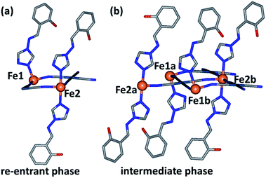 | ||
| Fig. 5 Asymmetric unit of 1Pt representative of (a) the parent cell (240, 120 and 90 K) and (b) the phase transition cell (192 and 170 K). | ||
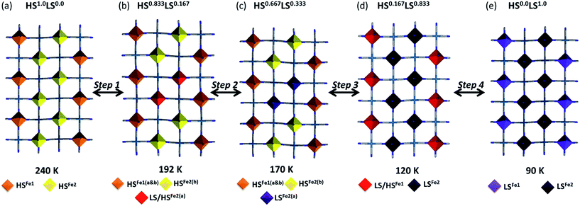
With further cooling, by 192 K, which represents the Step 1 plateau region, new reflections appear in each of the (½kl), (h½l) and (hk½) planes indicative of a three-dimensional unit cell transformation whereby the primitive triclinic symmetry is retained and the unit cell volume less than doubles (Tables S1 and S3†). Consequential to this phase transition, both the Fe1 and Fe2 sites split into two further unique sites, Fe1(a), Fe1(b), Fe2(a) and Fe2(b) such that there are now twice as many crystallographically distinct Fe(II) sites as in the parent cell (Fig. 5(b)). Of relevance to the magnetic properties, the relative ratio of these sites is 1Fe1(a)![[thin space (1/6-em)]](https://www.rsc.org/images/entities/char_2009.gif) :
:![[thin space (1/6-em)]](https://www.rsc.org/images/entities/char_2009.gif) 1Fe1(b)
1Fe1(b)![[thin space (1/6-em)]](https://www.rsc.org/images/entities/char_2009.gif) :
:![[thin space (1/6-em)]](https://www.rsc.org/images/entities/char_2009.gif) 2Fe2(a)
2Fe2(a)![[thin space (1/6-em)]](https://www.rsc.org/images/entities/char_2009.gif) :
:![[thin space (1/6-em)]](https://www.rsc.org/images/entities/char_2009.gif) 2Fe2(b). The Fe1(a), Fe1(b), Fe2(a) and Fe2(b) sites in this transformed phase are distributed within each Hofmann layer as depicted in Fig. 6(b), whereby there are complete stripes of Fe1(a) or Fe1(b) chains separated by pairs of Fe2(a) and Fe2(b) chains, where the two sites alternate along the a-axis.
2Fe2(b). The Fe1(a), Fe1(b), Fe2(a) and Fe2(b) sites in this transformed phase are distributed within each Hofmann layer as depicted in Fig. 6(b), whereby there are complete stripes of Fe1(a) or Fe1(b) chains separated by pairs of Fe2(a) and Fe2(b) chains, where the two sites alternate along the a-axis.
Careful assessment of diffraction images reveals that this new phase is present over the range 192–150 K, representative of Step 2, as observed using powder diffraction. Complete structural analysis at 192 K, representative of the 5/6 HS fraction plateau, indicates that the Fe1(a) and (b) sites retain an HS character along with the Fe2(b) site. The Fe2(a) sites show a 0.1 Å decrease in apparent Fe–N bond length indicating a 50![[thin space (1/6-em)]](https://www.rsc.org/images/entities/char_2009.gif) :
:![[thin space (1/6-em)]](https://www.rsc.org/images/entities/char_2009.gif) 50 mixed HS
50 mixed HS![[thin space (1/6-em)]](https://www.rsc.org/images/entities/char_2009.gif) :
:![[thin space (1/6-em)]](https://www.rsc.org/images/entities/char_2009.gif) LS state of short-ranged ordered Fe(II) spin states (Fig. 6(b)). Thus, in this phase there are 5HS and 1LS Fe(II) sites (1Fe1(a)HS
LS state of short-ranged ordered Fe(II) spin states (Fig. 6(b)). Thus, in this phase there are 5HS and 1LS Fe(II) sites (1Fe1(a)HS![[thin space (1/6-em)]](https://www.rsc.org/images/entities/char_2009.gif) :
:![[thin space (1/6-em)]](https://www.rsc.org/images/entities/char_2009.gif) 1Fe1(b)HS
1Fe1(b)HS![[thin space (1/6-em)]](https://www.rsc.org/images/entities/char_2009.gif) :
:![[thin space (1/6-em)]](https://www.rsc.org/images/entities/char_2009.gif) 1Fe2(a)HS
1Fe2(a)HS![[thin space (1/6-em)]](https://www.rsc.org/images/entities/char_2009.gif) :
:![[thin space (1/6-em)]](https://www.rsc.org/images/entities/char_2009.gif) 1Fe2(a)LS
1Fe2(a)LS![[thin space (1/6-em)]](https://www.rsc.org/images/entities/char_2009.gif) :
:![[thin space (1/6-em)]](https://www.rsc.org/images/entities/char_2009.gif) 2Fe2(b)HS), comprised of long- and short-range ordered spin states, consistent with magnetic measurements and a 5/6 HS fraction.
2Fe2(b)HS), comprised of long- and short-range ordered spin states, consistent with magnetic measurements and a 5/6 HS fraction.
Structural analysis at 170 K, representative of the 2/3 plateau, reveals that the Fe2(a) site converts completely to the LS state as illustrated in Fig. 6(c) (Table S3†). Thus, all Fe(II) sites show long-range ordering of the respective HS and LS states (1Fe1(a)HS![[thin space (1/6-em)]](https://www.rsc.org/images/entities/char_2009.gif) :
:![[thin space (1/6-em)]](https://www.rsc.org/images/entities/char_2009.gif) 1Fe1(b)HS
1Fe1(b)HS![[thin space (1/6-em)]](https://www.rsc.org/images/entities/char_2009.gif) :
:![[thin space (1/6-em)]](https://www.rsc.org/images/entities/char_2009.gif) 2Fe2(a)LS
2Fe2(a)LS![[thin space (1/6-em)]](https://www.rsc.org/images/entities/char_2009.gif) :
:![[thin space (1/6-em)]](https://www.rsc.org/images/entities/char_2009.gif) 2Fe2(b)HS), with the 4HS
2Fe2(b)HS), with the 4HS![[thin space (1/6-em)]](https://www.rsc.org/images/entities/char_2009.gif) :
:![[thin space (1/6-em)]](https://www.rsc.org/images/entities/char_2009.gif) 2LS ratio again agreeing with magnetic data at this temperature. During the abrupt spin transition process of Step 3, the additional superstructure reflections associated with the structural modulation diminish, reverting entirely to the parent cell by 150 K. The ‘parent cell’ is then retained at low temperatures. Structural analysis at 120 K, representative of the 1/6 plateau, reveals that all of the Fe2 sites convert entirely to the LS state and half of the Fe1 sites, resolved as a 50
2LS ratio again agreeing with magnetic data at this temperature. During the abrupt spin transition process of Step 3, the additional superstructure reflections associated with the structural modulation diminish, reverting entirely to the parent cell by 150 K. The ‘parent cell’ is then retained at low temperatures. Structural analysis at 120 K, representative of the 1/6 plateau, reveals that all of the Fe2 sites convert entirely to the LS state and half of the Fe1 sites, resolved as a 50![[thin space (1/6-em)]](https://www.rsc.org/images/entities/char_2009.gif) :
:![[thin space (1/6-em)]](https://www.rsc.org/images/entities/char_2009.gif) 50 mixed HS
50 mixed HS![[thin space (1/6-em)]](https://www.rsc.org/images/entities/char_2009.gif) :
:![[thin space (1/6-em)]](https://www.rsc.org/images/entities/char_2009.gif) LS state of short-range ordered Fe(II) spin states (Fig. 6(d) and Table S3†). This is consistent with a 1/6 HS Fe(II) fraction at this temperature (1Fe1HS
LS state of short-range ordered Fe(II) spin states (Fig. 6(d) and Table S3†). This is consistent with a 1/6 HS Fe(II) fraction at this temperature (1Fe1HS![[thin space (1/6-em)]](https://www.rsc.org/images/entities/char_2009.gif) :
:![[thin space (1/6-em)]](https://www.rsc.org/images/entities/char_2009.gif) 1Fe1LS
1Fe1LS![[thin space (1/6-em)]](https://www.rsc.org/images/entities/char_2009.gif) :
:![[thin space (1/6-em)]](https://www.rsc.org/images/entities/char_2009.gif) 4Fe2LS). As per the 5/6 plateau both long- and short-range ordering of Fe(II) spin states are represented. By 90 K, a complete LS character is attained for all Fe(II) sites as depicted in Fig. 6(e) (Table S3†). Thus there are 5 magnetically and structurally distinct states for this material, comprising of a range of long- and short-range ordered Fe(II) spin states and with novel nano-patternings of local spin states.
4Fe2LS). As per the 5/6 plateau both long- and short-range ordering of Fe(II) spin states are represented. By 90 K, a complete LS character is attained for all Fe(II) sites as depicted in Fig. 6(e) (Table S3†). Thus there are 5 magnetically and structurally distinct states for this material, comprising of a range of long- and short-range ordered Fe(II) spin states and with novel nano-patternings of local spin states.
Magneto-structural rationalisation
It is clear from the unique Fe(II) site distinctions in both the parent and phase transition states why a multi-step behaviour arises that is associated with integer sixth's fractions of HS Fe(II) states, i.e., 3 or 6 unique metal sites are present. What is less evident is why the 5/6, 4/6 and 1/6 states are stabilised in either subtle or distinct plateau regions, whereas other integer sixth fraction states (e.g., 2/6 and 3/6) are bypassed in the very abrupt transition of Step 3.In general, Fe(II) sites that are in a relatively less distorted octahedral environment will preferentially undergo an HS to LS transition upon cooling. In this case, the local Fe1 and Fe2 octahedral environments are in much the same distortive state (Table S3†). Considering that the overall intrinsic cooperativity of Hofmann materials stems from the short cyano-bridges of the Hofmann layer efficiently propagating spin state information, distortions within the layer are likely to play a significant role in stabilising the intermediate lattice states. Indeed, Hofmann-layer Fe–N![[triple bond, length as m-dash]](https://www.rsc.org/images/entities/char_e002.gif) C angles which are more idealised (i.e., 180°) would provide a favorable spin transition pathway owing to π-back-bonding effects. Indeed, here, the Fe2–N
C angles which are more idealised (i.e., 180°) would provide a favorable spin transition pathway owing to π-back-bonding effects. Indeed, here, the Fe2–N![[triple bond, length as m-dash]](https://www.rsc.org/images/entities/char_e002.gif) C angles are distinctly more regular compared to those of Fe1, and thus Fe2 transitions before Fe1 in the cooling profile. Of course this is a very simplistic rationale as there are evidently many other outer coordination sphere distinctions between Fe1 and Fe2 that would contribute to their relative HS stability. In any case, the deviation of these angles appears to only influence the initial onset of SCO and play little role thereafter, remaining essentially constant.
C angles are distinctly more regular compared to those of Fe1, and thus Fe2 transitions before Fe1 in the cooling profile. Of course this is a very simplistic rationale as there are evidently many other outer coordination sphere distinctions between Fe1 and Fe2 that would contribute to their relative HS stability. In any case, the deviation of these angles appears to only influence the initial onset of SCO and play little role thereafter, remaining essentially constant.
With cooling from the HS state phase, the Fe1 and Fe2 sites each distinguish into further unique sites via a single crystal phase transition, resulting in a subtle plateau (of four long-range ordered HS sites and two short-range ordered ‘mixed’ HS/LS sites) followed by a thermally stable plateau (of four HS sites and two LS sites long-range ordered). The driving force for the phase transition and plateau stabilisation is clear when the resultant octahedral distortions are considered (Table S3†). Of particular note is the increase in octahedral distortion at a number of these sites with cooling despite retaining an HS character (i.e., Step 1: ΣFe1 18° → ΣFe1(b): 23.3° and Step 2: ΣFe1(a) 17.6° → ΣFe1(a): 26.4°). This effect, termed negative- (or anti-) cooperativity,13,32,33 which is of antiferro-elastic origin, has been noted previously in systems such as this and dinuclear materials where there are strong coordination pathways between SCO sites. Thus volumetric HS → LS variations of nearby sites are strongly communicated (i.e., lattice cooperativity). As the lattice cannot accommodate these changes, nearby sites must adjust by becoming more irregular, i.e., increased HS stability, thus the term anti-cooperativity is employed to represent antiferro-elastic-like effects. Hence, the Step 1 and Step 2 plateau regions (and the associated phase transition) are enabled by strong lattice cooperativity which results in negative-communication effects and the stabilisation of these sites in the HS state.
A clear feature in the spin transition curve is the abrupt spin state transition of Step 3, which bypasses the potential spin state fractions of 3/6 and 2/6 resulting in a 1/6 HS fractional state. In this step, the Fe1 and Fe2(a) and (b) sites, respectively, are no longer crystallographically distinct (i.e., re-entrant phase transition state) and the relative octahedral distortion parameter proceeds in the usual manner. However, it is of note that the Fe1 site is substantially more distorted at this temperature than at 240 K indicating anti-cooperativity is still a governing factor (i.e., the lattice has not yet obtained energy minimisation). Thus, this abrupt step is facilitated by strong lattice cooperativity, which encourages all of the Fe2 sites to attain LS character in one step and half of the Fe1 sites to transition. The fact that both Fe1 and Fe2 sites transition in a concerted manner in this step (hence bypassing 3/6 and 2/6 plateau options) further illustrates the efficient lattice cooperativity of this system. Furthermore, it is likely that the distinctly large distortion parameter observed for the Fe1(a) site in Step 3 (ΣFe1(a): 26.4°) inhibits a full conversion of all Fe(II) sites to the LS state in this step. Moreover this relatively distorted site enables thermal stability of this state at relatively low temperatures, such that the Step 4 transition to a completely LS state is only thermally accessible at temperatures below 90 K.
Conclusions
In summary, we have presented a rare example of a four-stepped SCO material enabled by the strategic incorporation of structure directing interaction sites (in particular hydrogen bonding sites) in combination with a framework topology with intrinsic solid state cooperativity. The presence of five structurally distinct spin state phases, encompassing a unique array of short- and long-range ordered Fe(II) spin state arrangements, is directly facilitated by these flexible interactions. In particular, lattice distortions are present and stabilised here by a rich variety of host–host and host–guest interactions with the ligand –OH functional group. As distinct from other Hofmann-type materials displaying multi-step SCO, quite different layer periodicity has been obtained as a direct consequence of using an asymmetric ligand. The fact that the specific spin state patternings achieved here are new indicates that there is not one common series of transitions that the Hofmann layer can undergo. This study highlights that multi-stable electronic switching character is achieved though the presence of lattice distortive interactions; however, the variety of multistep behaviours now reported indicate that there is no common structural facet underlying these frustration effects.With examples of four-stepped spin transitions being rare, detailed studies encompassing parallel structural and magnetic correlations are essential for fundamental appreciation and to enable future targeted synthetic approaches. Our comprehensive structure–function correlation studies highlight the intrinsic necessity to conduct thorough analysis to completely understand such complex behaviours; most significantly, we would state the importance of conducting structural analyses on both bulk powders and single crystal samples over a broad temperature range to ensure that multi-stepped transitions apparent in magnetic susceptibility measurements are not due to the presence of multiple phases with differing SCO behaviours.
Acknowledgements
CJK and SMN acknowledge support from Fellowships and Discovery Project funding from the Australian Research Council. GC and JFL thank the Aquitaine Region for supporting the development of the international platform of photomagnetism. Access and use of the facilities of the Advanced Photon Source (APS) was supported by the USA Department of Energy, Office of Science, Office of Basic Energy Sciences (Contract No. DE-AC02–06CH11357). Travel to the APS was funded by the International Synchrotron Access Program (ISAP) managed by the Australian Synchrotron and funded by the Australian Government.Notes and references
- O. Kahn, Molecular Magnetism, VCH, New York, 1993 Search PubMed.
- P. Gütlich and H. A. Goodwin, Top. Curr. Chem., 2004, 233, 1–47 CrossRef.
- M. A. Halcrow, Spin-crossover materials: properties and applications, John Wiley & Sons, Ltd, 2013 Search PubMed.
- P. Gütlich, A. B. Gaspar and Y. Garcia, Beilstein J. Org. Chem., 2013, 9, 342–391 CrossRef PubMed.
- P. Gütlich, A. Hauser and H. Spiering, Angew. Chem., Int. Ed. Engl., 1994, 33, 2024 CrossRef.
- O. Kahn and C. J. Martinez, Science, 1998, 279, 44–48 CrossRef CAS.
- J. A. Real, A. B. Gaspar and M. C. Muñoz, Dalton Trans., 2005, 2062 RSC.
- P. Gütlich, Y. Garcia and T. Woike, Coord. Chem. Rev., 2001, 219–221, 839 CrossRef.
- J. A. Real, A. B. Gaspar, V. Niel and M. C. Muñoz, Coord. Chem. Rev., 2003, 236, 121–141 CrossRef CAS.
- J.-F. Létard, P. Guionneau and L. Goux-Capes, Top. Curr. Chem., 2004, 235, 221–249 CrossRef.
- M. Halcrow, Chem. Soc. Rev., 2011, 40, 4119–4142 RSC.
- M. Paez-Espejo, M. Sy and K. Boukheddaden, J. Am. Chem. Soc., 2016, 138, 3202–3210 CrossRef CAS PubMed.
- Y. M. Klein, N. F. Sciortino, F. Ragon, C. E. Housecroft, C. J. Kepert and S. M. Neville, Chem. Commun., 2014, 50, 3838–3840 RSC.
- J. J. Amoore, C. J. Kepert, J. D. Cashion, B. Moubaraki, S. M. Neville and K. S. Murray, Chem.–Eur. J., 2006, 12, 8220–8227 CrossRef CAS PubMed.
- S. M. Neville, B. A. Leita, G. J. Halder, C. J. Kepert, B. Moubaraki, J.-F. Létard and K. S. Murray, Chem.–Eur. J., 2008, 14, 10123–10133 CrossRef CAS PubMed.
- Y. Garcia, O. Kahn, L. Rabardel, B. Chansou, L. Salmon and J. P. Tuchagues, Inorg. Chem., 1999, 38, 4663–4670 CrossRef CAS PubMed.
- J. Tnag, J. S. Costa, S. Smulders, G. Molnár, A. Bousseksou, S. J. Teat, Y. Li, G. Albada, P. Gamez and J. Reedijk, Inorg. Chem., 2009, 48, 2128–2135 CrossRef PubMed.
- D. Chernyshov, M. Hostettler, K. W. Törnroos and H.-B. Bürgi, Angew. Chem., Int. Ed., 2003, 42, 3825–3830 CrossRef CAS PubMed.
- S. Bonnet, M. A. Siegler, J. S. Costa, G. Molnár, A. Bousseksou, A. L. Spek, P. Gamez and J. Reedijk, Chem. Commun., 2008, 5619–5621 RSC.
- M. Griffin, S. Shakespeare, H. J. Shepherd, C. J. Harding, J.-F. Létard, C. Desplanches, A. E. Goeta, J. A. K. Howard, A. K. Powell, V. Mereacre, Y. Garcia, A. D. Naik, H. Müller-Bunz and G. G. Morgan, Angew. Chem., Int. Ed., 2011, 50, 896–900 CrossRef CAS PubMed.
- B. J. Vieira, J. T. Coutinho, I. C. Santos, L. C. Pereira, J. C. Waerenborgh and V. da Gama, Inorg. Chem., 2013, 52, 3845–3850 CrossRef CAS PubMed.
- D. Boinnard, A. Bousseksou, A. Dworkin, J.-M. Savariault, F. Varret and J.-P. Tuchagues, Inorg. Chem., 1994, 33, 271–281 CrossRef CAS.
- C.-F. Sheu, S. Pillet, Y.-C. Lin, I.-J. Hsu, C. Lecompte and Y. Wang, Inorg. Chem., 2008, 47, 10866–10874 CrossRef CAS PubMed.
- M. Nihei, H. Tahira, N. Takahashi, Y. Otake, Y. Yamamura, K. Sato and H. Oshio, J. Am. Chem. Soc., 2010, 132, 3553–3560 CrossRef CAS PubMed.
- N. F. Sciortino, K. R. Scherl-Gruenwald, G. Chastanet, G. J. Halder, K. W. Chapman, J.-F. Létard and C. J. Kepert, Angew. Chem., Int. Ed., 2012, 51, 10154–10158 CrossRef CAS PubMed.
- E. Trzop, D. Zhang, L. Piñeiro-Lopez, F. J. Valverde-Muñoz, M. C. Muñoz, L. Palatinus, L. Guerin, H. Cailleau, J. A. Real and E. Collet, Angew. Chem., Int. Ed., 2016, 55, 8675–8679 CrossRef CAS PubMed.
- J. E. Clements, J. R. Price, S. M. Neville and C. J. Kepert, Angew. Chem., Int. Ed., 2016 DOI:10.1002/anie.201605418.
- R. Otahani, M. Arai, H. Ohba, A. Hori, M. Takata, S. Kitagawa and M. Ohba, Eur. J. Inorg. Chem., 2013, 738–744 CrossRef.
- V. Martinez, Z. A. Castillo, M. C. Muñoz, A. B. Gaspar, C. Etrillard, J.-F. Létard, S. A. Terekhov, G. V. Bukin, G. Levchenko and J. A. Real, Eur. J. Inorg. Chem., 2013, 813–818 CrossRef CAS.
- N. F. Sciortino, S. M. Neville, J.-F. Létard, B. Moubaraki, K. S. Murray and C. J. Kepert, Inorg. Chem., 2014, 53, 7886–7893 CrossRef CAS PubMed.
- S. M. Neville, G. J. Halder, K. W. Chapman, M. B. Duriska, P. D. Southon, J. D. Cashion, J.-F. Létard, B. Moubaraki, K. S. Murray and C. J. Kepert, J. Am. Chem. Soc., 2008, 130, 2869–2876 CrossRef CAS PubMed.
- S. G. Telfer, B. Bocquet and A. F. Williams, Inorg. Chem., 2001, 40, 4818–4820 CrossRef CAS PubMed.
- C. M. Grunert, S. Reiman, H. Spiering, J. A. Kitchen, S. Brooker and P. Gütlich, Angew. Chem., Int. Ed., 2008, 47, 2997–2999 Search PubMed.
Footnote |
| † Electronic supplementary information (ESI) available: Characterisation of materials. CCDC 1038403–1038407. For ESI and crystallographic data in CIF or other electronic format see DOI: 10.1039/c6sc03114e |
| This journal is © The Royal Society of Chemistry 2017 |

