Local and overall heat transfer of exothermic reactions in microreactor systems
Received
13th June 2017
, Accepted 29th August 2017
First published on 5th September 2017
Abstract
Non-reactive and reactive heat transfer experiments were performed in the FlowPlate® system manufactured by Ehrfeld Mikrotechnik, which is composed of alternating reactor and heat transfer fluid plates within a rack. The non-reactive model system studied a rectangular serpentine channel with Reynolds numbers ranging from 400–2000, and a Gnielinski-type model was fit to the internal Nusselt number. A silver-based thermal paste was shown to reduce the external resistance to heat transfer between the reactor and heat transfer fluid plates by ∼70%, leading to overall heat transfer coefficients of ∼2200 W m−2 K−1. In the reactive system, the synthesis of methyl 2-oxobutanoate, using dimethyl-oxalate and the Grignard reagent ethylmagnesium chloride, was highlighted as a test reaction to differentiate localized heat transfer characteristics across different reactors. The Grignard reaction was used to compare the impact of various micro-mixer geometries, materials, injection ports, and scales on hotspot formation in the reactors. Finally, an analysis of four case studies that can be extended to any micro-reactor system with known overall heat transfer coefficients was presented using the fourth Damköhler number to determine a maximum channel diameter that would remove energy sufficiently quick to avoid hotspot formation.
1. Introduction
The field of continuous-flow micro-reactor technology has gained academic and industrial interest in recent years due to its many advantages over batch processes at smaller scales.1–4 Micro-reactors potentially offer enhanced transport rates including wall-to-fluid heat transfer due to relatively small channel dimensions and high surface-area-to-volume ratios when compared to batch or larger-scale continuous flow reactors.1–7 Notwithstanding the fact that a single micro-reactor is not a general solution to all type of reactions,8 Plouffe et al. developed a toolbox approach where the preferred reactor system is chosen for the given reaction rate, reaction network, and phase(s) type.9 This toolbox encompasses the use of micro-structure plates where beneficial, namely during the intense mixing/heat exchange portion of a reaction, while more conventional modules like a coil or tubular heat exchangers are used afterward for an effective increase in volume.
In relation to heat exchange, three cases can be considered which are a function of the reaction rate (type A, B, and C). For type A reactions (millisecond to second), even with micro-structures, a hotspot can be formed and, in general, it is controlled via the multi-injection principle.10 Organo–Grignard reactions are an example of intensely exothermic type A systems with a complex network of reactions that occur in the hotspot.11 The Grignard reaction reported by Plouffe et al.,9 which shows a very high resolution in side-product formation as a function of the hotspot magnitude, makes it well-suited to understand localized heat effects. It will be used here to study different micro-reactor systems further. Type B reactions have intermediate kinetics (between several seconds and minutes), but may still be fast enough to require significant heat exchange to reduce spatial variations in thermal conditions. A multi-scale approach is appropriate where the hydraulic diameter of a reactor is adjusted via a different plate or coil diameter depending on the local reaction kinetics (vide infra). Type C reactions have slower kinetics (between several minutes to hours) and can often be handled by conventional technology,9 except for cases with particularly hazardous chemicals or operating conditions.
The scale-up of production using micro-structures is often limited by the pressure drop, and a plate type reactor is generally more straightforward to scale up than a coil reactor. Fig. 1 shows a mix-then-reside (MTR) plate, where the initial mixing zone (in this case SZ) is the main contributor to the pressure drop of the plate. The hydraulic diameter of this mixing zone can be adjusted for various flow rates via the 3/7th power rule as explained in ref. 12. On the other hand, upon scale-up, the residence time channel (RTC) may be enlarged in width (w) while the depth (d) is kept constant to maintain similar hydrodynamic conditions (and similar hin) and hydraulic diameter, leading also to a similar specific surface area for heat exchange (a). In fact, when such an approach is integrated into various sized plates (as seen in Fig. 2, FlowPlate® Lab: 1.5–15 mL min−1; A6: 15–150 mL min−1; A5: 150–300 mL min−1;…), pressure drop can be kept reasonable for a single plate, leading to high flow rates and productivity. Combined with a multi-scale approach, even longer residence times can be accommodated with the proper reactor unit while maintaining relatively low pressure losses. In other words, the size increase of a plate is consistent with the increase of volume (V) and surface area leading to a consistent scale-up, as opposed to the increase of the diameter of a coil; where a is inversely proportional to V.
 |
| | Fig. 1 FlowPlate® Lab SZ mix-then-reside (MTR) reactor plates manufactured by Ehrfeld Mikrotechnik size 600 (left) and 300 (right). | |
 |
| | Fig. 2 FlowPlate® Lab, A6, and A5 systems (from left to right). | |
This work is focused on characterizing and developing models for the overall heat transfer performance of RTC plates and utilizing an exothermic test reaction to study the localized heat transfer in various MTR plates. The results are then used to understand the fluid-to-wall heat exchange capabilities and limitations of the plate micro-reactors for four different reaction case-studies.
1.1. Dimensionless approach to heat transfer and common models
While it is generally accepted that the heat transfer in micro-reactors benefits from the inherent smaller-length scales, the heat transfer performance is not fully understood since a micro-channel is rarely a simple straight channel for which the classic wall-to-fluid heat transfer correlations were developed.13 For heat transfer studies in micro-reactors and micro-channels, there is little agreement in the literature on whether conventional, macro-scale correlations apply to the smaller-scale systems.7,13–15 Morini,14 as well as Steinke and Kandlikar,15 performed literature reviews on the available heat transfer data and found little consistency, concluding that further work is required in the field. Morini observed that when analyzing all data chronologically, the overall deviations between studies were decreasing. This trend was attributed to the technological improvements in the construction of the micro-channels, reducing the relative roughness and uncertainties in channel dimensions. Steinke and Kandlikar considered three key underlying causes specific to research in micro-reactor systems responsible for the differences in various investigations:7,15 the thermal entrance regions in relatively short micro-reactors; uncertainties in experimental measurements (e.g. small channel dimensions, wall temperatures, etc.); and ambiguity in the determination of the thermal boundary condition. These factors were taken into account when developing the experimental protocols used in this work.
For macro-scale systems in the fully developed laminar flow regime (Re < 2300), the Nusselt number is typically constant for straight channels;16 while in the transitional (2300 < Re < 10![[thin space (1/6-em)]](https://www.rsc.org/images/entities/char_2009.gif) 000) and turbulent (Re > 10000) flow regimes, Nu can be described in terms of Re and Pr. Many studies claim that there is an early transition to turbulence in micro-channels; however, Steinke and Kandlikar showed that these studies did not account for developing flow or uncertainty in their calculations.15 Nevertheless, due to the curvature of the micro-channels studied here, vortices can form, and secondary flow patterns can become chaotic at Reynolds numbers below typical transitional flow conditions,17–21 even when high aspect ratios (a) are employed.22 These chaotic flow patterns are suspected to influence the Nusselt number in similar ways to turbulent flow, rather than Nu remaining constant, as in laminar flow. For this reason, several empirical Nusselt number correlations that are valid for transitional and turbulent flow regimes (Re > 2300), regardless of boundary conditions,13 are considered, even though the range of this study is 400 < Re < 2000. It is worth noting that the channels studied here in this range of Reynolds numbers can be considered hydraulically smooth, as the relative roughness is approximately 4 × 10–4.23
000) and turbulent (Re > 10000) flow regimes, Nu can be described in terms of Re and Pr. Many studies claim that there is an early transition to turbulence in micro-channels; however, Steinke and Kandlikar showed that these studies did not account for developing flow or uncertainty in their calculations.15 Nevertheless, due to the curvature of the micro-channels studied here, vortices can form, and secondary flow patterns can become chaotic at Reynolds numbers below typical transitional flow conditions,17–21 even when high aspect ratios (a) are employed.22 These chaotic flow patterns are suspected to influence the Nusselt number in similar ways to turbulent flow, rather than Nu remaining constant, as in laminar flow. For this reason, several empirical Nusselt number correlations that are valid for transitional and turbulent flow regimes (Re > 2300), regardless of boundary conditions,13 are considered, even though the range of this study is 400 < Re < 2000. It is worth noting that the channels studied here in this range of Reynolds numbers can be considered hydraulically smooth, as the relative roughness is approximately 4 × 10–4.23
The Dittus–Boelter correlation was the simplest model considered where NuDB is a function of Re0.8. This model is typically sufficient when the fluid properties can be assumed to be constant across the studied temperature range13 and was developed for 0.6 ≤ Pr ≤ 160 and Re ≥ 10000. The Sieder–Tate correlation (NuST, valid for 0.7 ≤ Pr ≤ 16700 and Re ≥ 10000) extends upon this by incorporating a ratio between μ, the viscosity evaluated at the bulk temperature (![[T with combining macron]](https://www.rsc.org/images/entities/i_char_0054_0304.gif) c), and μs, the viscosity evaluated at the surface temperature, Ts. This model is more accurate when there are larger temperature gradients in the system, as it accounts for the transport phenomena at the boundary conditions.13
c), and μs, the viscosity evaluated at the surface temperature, Ts. This model is more accurate when there are larger temperature gradients in the system, as it accounts for the transport phenomena at the boundary conditions.13
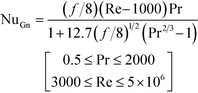
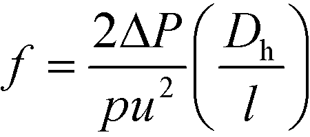
Lastly, the Gnielinski correlation (NuGn) was considered because it is an accurate model for transitional and turbulent regimes, since it incorporates a friction factor into its calculation, shown in eqn (1). The Darcy–Weisbach friction factor, f, used in its calculation is given in eqn (2), where ΔP is the pressure loss, in [Pa], across the reactor length l, in [m].
| |  | (1) |
| |  | (2) |
The Gnielinski correlation was developed for macro-scale applications, and Adams et al. showed that the correlation is sufficient in modeling Nu for non-circular channels with Dh as small as 1.2 mm.24 They also showed that for smaller channel sizes, such as those studied here, a deviation factor can be applied to the Gnielinski correlation to achieve better predictions for Nu.25 Although the Gnielinski model (with the deviation factor from Adams) would have been the preferred model, the term (Re − 1000) would become negative for the range of flows that were studied, and this would not yield meaningful results. Therefore, a modified Gnielinski model will be developed as in eqn (3) where β and γ will be fit using the least squared error, ensuring that β is smaller than smallest Re studied (400).
| |  | (3) |
2. Experimental and analytical methods
2.1. Reactors studied
2.1.1. RTC plate used with a non-reactive system.
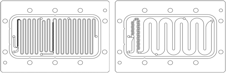
The first investigation utilized an A6-sized FlowPlate® reactor manufactured by Ehrfeld Mikrotechnik (Fig. 2); namely, the 320B, which is a RTC using half of the plate's area, shown in Fig. 3. This RTC plate was chosen because it has a smaller operating volume with the same channel dimensions as the standard 321 RTC plate, which uses the entire A6 plate. The ‘B’ side was chosen over the ‘A’ side for ease of setup due to both inlet and outlet facing upwards, in addition to having more curves relative to the total volume, similar to the RTC sections on several MTR plates. The detailed dimensions of this plate can be found in Table 1. The RTC plate (in addition to the A5-sized plates used in the reactive system discussed below) was manufactured out of a 3.5 mm thick Hastelloy® C22 plate with a 1.5 mm plate welded to the other side; so, the metal's thickness is dependent on the channel's depth at that point. The thermal conductivity of Hastelloy® C22 is 10.9 W m−1 k−1,26 significantly lower than that of aluminium (273 W m−1 k−1 at 300 K)23 with which the Heat Transfer Fluid (HTF) plates were made (newer HTF plates are manufactured with copper with k = 400 W m−1 k−1 (ref. 23)). The reactor plates and heat transfer fluid plates alternate in the FlowPlate® system, as shown in Fig. 2. The HTF flow is operated in the turbulent regime at Reynolds numbers over 15000 to minimize the resistance to fluid-to-wall heat transfer in the HTF channel.
 |
| | Fig. 3 CAD drawings of the 320 RTC plate. | |
Table 1 Reactor plate properties
| Parameter |
320B |
315 |
215 |
240 |
260 |
350 |
[Units] |
|
Not truly a size 200 due to reduced channel depth.
|
| Plate size |
A6 |
A6 |
A5 |
A5 |
A5 |
A5 |
|
| Plate material |
Hastelloy® |
Hastelloy® |
Hastelloy® |
Hastelloy® |
Hastelloy® |
SiC |
|
| Plate type |
RTC |
MTR |
MTR |
MTR |
MTR |
MTR |
|
| Mixing zone |
| Mixer type |
— |
SZ |
SZ |
TG |
TG |
TG |
|
| Mixer size |
— |
300 |
200 |
200 |
100 |
200a |
|
|
D
h
|
— |
0.714 |
1.00 |
1.00 |
1.375 |
0.747 |
[mm] |
|
w
|
— |
0.5 |
0.7 |
0.7 |
1.0 |
0.7 |
[mm] |
|
d
|
— |
1.25 |
1.75 |
1.75 |
2.2 |
0.8a |
[mm] |
|
A
ME
|
— |
4.61 × 10⁻⁵ |
8.40 × 10⁻⁵ |
8.84 × 10⁻⁵ |
1.85 × 10⁻⁴ |
6.50 × 10⁻⁵ |
[m2] |
|
V
ME
|
— |
6.74 × 10⁻⁹ |
1.7 × 10⁻⁸ |
3.96 × 10⁻⁸ |
1.02 × 10⁻⁷ |
1.81 × 10⁻⁸ |
[m3] |
| Specific area |
— |
6840 |
4890 |
2230 |
1820 |
3590 |
[m2 m−3] |
| Residence time channel |
|
D
h
|
0.901 |
0.901 |
0.952 |
1.38 |
1.31 |
1.38 |
[mm] |
|
w
|
5.0 |
5.0 |
10.0 |
5.0 |
10.0 |
5.0 |
[mm] |
|
d
|
0.5 |
0.5 |
0.5 |
0.8 |
0.7 |
0.8 |
[mm] |
|
l
|
617 |
— |
— |
— |
— |
— |
[mm] |
|
A
R
|
0.00679 |
— |
— |
— |
— |
— |
[m2] |
|
V
R
|
1.54 × 10⁻⁶ |
— |
— |
— |
— |
— |
[m3] |
| Specific area |
4400 |
— |
— |
— |
— |
— |
[m2 m−3] |
|
R
c
|
4.5 |
— |
— |
— |
— |
— |
[mm] |
2.1.2. MTR plates used with a reactive system.
For the reactive system, the five MTR plates from Table 1 were used; each with a different mixer type (SZ or TG, as shown in Fig. 4), scale (300, 200, or 100) or material (Hastelloy® C22 or SiC). Since the reaction is fast and occurs within a few milliseconds inside the reactor plate,9 it is only the geometry of a particular mixing-element that is of interest when comparing the five different plates. It is important to note that plate 350, the SiC TG plate, was custom built and has the HTF built into the plate (i.e., there is no contact resistance). The four other MTR plates fit into the FlowPlate® reactor system (either the size A5 or A6 rack, depending on the plate) as with the non-reactive system described previously.
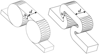 |
| | Fig. 4 3D representations of TG (left) and SZ (right) mixing elements. | |
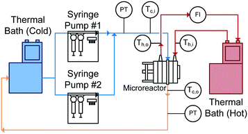
2.2. Heat transfer experiment setup for non-reactive system
With reactor plates and heat transfer fluid plates alternating in the FlowPlate® system, heat is transferred to both sides of the plate. Two Huber Ministat 230 thermal baths were used; one cooled the reactor side feed down to 5 °C, while the other circulated hot water through the HTF channels at 90 °C. Two Syrdos syringe pumps from Hitec-Zang metered in the chilled water from the bath at the desired volumetric flow rates, while the hot thermal bath's internal pump circulated the hot water (measured by a calibrated in-line rotameter). Flow rates in the HTF plates ranged from 5.2–6.8 L min−1, and flow inside the RTC ranged from 27 mL min−1 to 110 mL min−1. The standard range for the A6 plates used are generally from 15–150 mL min−1; however, the lower flow rates reached thermal equilibrium with the HTF before the outlet (meaning no analysis was possible). At the higher flow rates, the internal resistance to convective heat transfer became too small of a fraction (<10%) of the total resistance, so the calculation of the Nusselt number contained significant relative error.
The overall setup used is shown in Fig. 5. Temperatures were measured with four T-type thermocouples (Omega) at the inlet and outlet for both the reactor being studied (Tc,i and Tc,o) and the HTF channels (Th,i and Th,o). The pressure drop (ΔP) was also measured across the reactor using an Omegadyne PX409 0–17.5 bar differential pressure transducer to ensure no blockage was present in the channels and to measure the friction factor.
 |
| | Fig. 5 Schematic of heat transfer experimental setup. | |
When assembling the FlowPlate® system, the plates were tightened to a torque of 15 N m, the specification given by the manufacturer. This was maintained for all experiments because this would significantly affect the contact resistance between the plates. A silver-based thermal paste purchased from McMaster-Carr was used to test the contact resistance. It was chosen due to its high thermal conductivity of (104 W m−1 K−1) in order to fill any gaps between the plates.27
In order to insulate the system from the environment, a Styrofoam box was constructed with the required ports for the fluids to enter and exit the system, as well as the instrumentation wiring. The FlowPlate® A6 rack was in the box, surrounded by fiberglass insulation. This was done to ensure that the experiments were unaffected by the surrounding ambient temperature.
2.2.1. Water properties at temperatures studied.
The properties of water could not be assumed as constant throughout the reactor since this work was performed over a relatively wide range of temperatures (5–90 °C). The values for each property used at various temperatures are shown in Table 2.28 Note that, unless specified otherwise (e.g. viscosity at the wall temperature), the properties are evaluated at the average cold-side or hot-side temperatures, c and h, respectively.
Table 2 Physical properties of water at various temperatures28
| Temperature [°C] |
ρ [kg m−3] |
μ [× 104 Pa s] |
k [W m−1 k−1] |
c
p [J kg−1 K−1] |
| 5 |
999.9 |
15.18 |
0.571 |
4205 |
| 25 |
997.0 |
8.900 |
0.607 |
4182 |
| 45 |
990.2 |
5.958 |
0.637 |
4180 |
| 70 |
977.7 |
4.035 |
0.663 |
4190 |
| 90 |
965.3 |
3.141 |
0.675 |
4205 |
2.3. Heat transfer setup for Grignard reaction
At conditions similar to those presented in ref. 9, the synthesis of methyl 2-oxobutanoate (Fig. 6: 2-MOB, 3) was carried out in the MTR reactors from Table 1 using dimethyl-oxalate (DMO, 1) and the Grignard reagent ethylmagnesium chloride (2). The reaction network is shown in Fig. 6. Feed 1 consisted of 15 wt% DMO in dimethoxyethane (DME) and feed 2 had 19 wt% Grignard reagent, 58 wt% THF, and 23 wt% DME. Feeds 1 and 2 were maintained such that the ratio of Grignard:DMO remained 1.10 mol/mol. Both feeds were pre-cooled to the reactor's HTF temperature before mixing (either −5, −15, or −25 °C). The reaction was quenched with 1 mol L−1 HCl solution (HCl/Mg = 1.20 mol/mol) at the reactor outlet, and the yield was calculated as area percent from gas chromatography of 3 and the conjugated enol, 4.
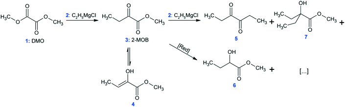 |
| | Fig. 6 Reaction network for the synthesis of methyl 2-oxobutanoate (DMO). | |
2.4. Analytical methods
2.4.1. Isolation of Nu from experimental data.
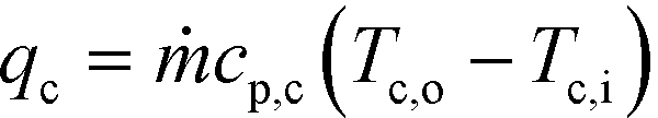
In order to determine the Nusselt number for a given channel, an energy balance is performed on the cold stream (the inner channel). The energy gained by the cold stream (qc) is equal to the heat transferred across the channel wall (qw) as defined by eqn (4) and (5), respectively.| | 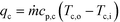 | (4) |
where ṁ is the mass flow rate (in [kg s−1]); cp,c is the heat capacity of the cold stream (in [J kg−1 K−1]); Tc,i and Tc,o are the fluid inlet and outlet temperatures, respectively; UAHE is the product of the overall heat transfer coefficient and area available for heat transfer across the wall (in [W K−1]); and ΔTLM is the log mean temperature difference defined in equation below. Since the HTF follows a serpentine path on either side of the reactor plates in opposite directions, it cannot be assumed to be either co-current or counter-current. However, the HTF flow is sufficiently high (as will be shown) and less than 1 °C is lost; allowing for the approximation of constant HTF temperature at h (the average hot side temperature).| | 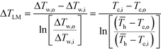 | (6) |
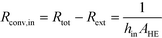
After equating eqn (4) and (5), it is possible to calculate UAHE for every experimental point. To isolate the convective heat transfer coefficient of the inner channel, hin, the system is expressed in terms of thermal resistances as a thermal circuit in Fig. 7. The total thermal resistance, Rtot, or 1/UAHE, is plotted vs. 1/Rein. When Rein approaches infinity, the thermal resistance due to internal convection, Rconv,in, approaches zero. The intercept of the plot of 1/UAHEvs. 1/Re is therefore equal to Rext; which is the sum of all thermal resistances between the hot and cold streams excluding Rconv,in. hin (and therefore Nu) can now be calculated using eqn (7) to (9) at each data point by calculating the constant Rext for a given data set. While the resistances to conduction through the plate walls are constants determined by the thickness and thermal conductivity of the metal, it is possible to manipulate the resistance due to convection in the heat transfer fluid (Rconv,out) and the contact resistance between the aluminium and Hastelloy® C22 plates (Rcontact).
| |  | (7) |
| | | Rext = Rconv,out + RcondHTF Plate + Rcontact + RcondMR Plate | (9) |
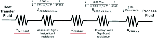 |
| | Fig. 7 Thermal circuit diagram between heat transfer fluid and process fluid; highlighting potentially significant external resistances in red. | |
3. Results and discussion
As previously mentioned, when the flow rate is increased in a system with alternating (right/left) curved channels, the Dean vortices can become chaotic while Re is still below 2300.17 This is the case with the results presented, as evident in the pressure loss and friction factor results for the entire plate (including inlet/outlet) vs. Re shown in Fig. 8. Fitting the friction factor results to a model as in eqn (10) is applicable due to localized regions of chaotic flow in the bends.17 This yields a fc of 0.105, which accounts for 25–50% of the total friction factor for the lowest and highest flow rate studied, respectively, indicating that a heat transfer model that accounts for transitional/turbulent flow may fit the results. While turbulent flow is often associated with a constant friction factor, this is not the case with hydraulically smooth pipes where the friction factor is still decreasing at Reynolds numbers above 108.23 It is due to the changing nature of the observed friction factor that the Gnielinski model was used as a basis to model the heat transfer in the RTC.| |  | (10) |
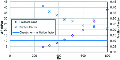 |
| | Fig. 8 Pressure loss and friction factor vs. Re for the 320B RTC. | |
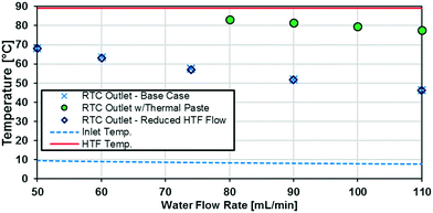
The raw temperature data from various experiments is presented in Fig. 9. The HTF temperature (the theoretical maximum for any reactor plate outlet temperature) is the average of the inlet and outlet temperatures to the jacket side, which ranged no more than 1 °C. The inlet temperature varied with flow rate because of the syringe residence time before entering the insulated system.
 |
| | Fig. 9 Temperature vs. internal water flow rate for various conditions for the 320B-RTC. | |
3.1.1. RTC Base case.
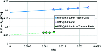
The base case for the RTC uses no thermal paste between the HTF and RTC plates. It also uses the maximum HTF flow rate available, 6.8 L min−1. The external resistance used for the calculation of hin and Nu as in eqn (7) can be seen in the base case results in Fig. 10 when Re approaches infinity at the intercept where 1/Re is equal to zero. Note that the external resistance accounts for 85–90% of the total resistance. This can be significantly reduced, as discussed in section 3.1.2, but these conditions were required to obtain reliable Nu numbers (internal convection) with sufficient experimental points, and ΔT (see Fig. 9).
 |
| | Fig. 10 Total thermal resistance vs. 1/Re. | |
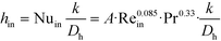
The base case results from Fig. 10 can be used to calculate the experimental Nusselt number, as shown in Fig. 11. Applying a least squares fit to the model from eqn (3) yielded values of 141 and 18.5 for β and γ, respectively. Clearly, the Nusselt number is not constant with respect to Re as predicted by laminar flow in a straight channel; indicating that the primary mechanism of heat transfer is from chaotic eddies generated in the channel's curvature. Indeed, when fitting the Nu results to a Sieder–Tate type model, the exponent for Re is 0.85 ± 0.12 compared to the expected value of 0.8 for turbulent flow (as used in eqn (12)).
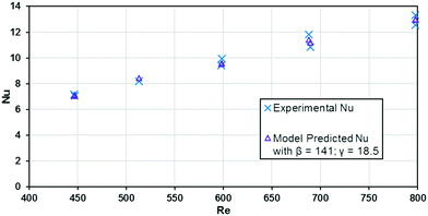 |
| | Fig. 11 Nusselt number (experimental and predicted) vs. Reynolds number for the 320B RTC. | |
3.1.2. Reduction of external resistances in the FlowPlate®.
This reactor's technology was designed to minimize the external heat transfer resistance so that the main contribution comes from the internal resistance to convection. One approach is to operate with a large excess of thermal fluid in an isolated loop to minimize thermal losses. The intention is not optimized heat exchange efficiencies in a counter-current mode, but rather a rapid temperature homogenisation to avoid localized hotspot formation due to reactions. In such a case, the design of the thermal fluid channel did not need to be micro-structured but was instead designed for operation in the turbulent regime to maximize heat transfer capability. The typical Re number (with water as HTF and flow rate of 6.8 L min−1) is 15000. The HTF plates have the additional advantage of using aluminum or copper (high k metals), because the chemical compatibility is not an issue as in the reactor plates (which use Hastelloy® C22).
As previously noted, the external resistance was relatively high compared to the internal resistance to convection. To ensure Rconv,out is minimized, the HTF flow rate must be increased towards infinity; however, the thermal bath was already operating at maximum flow rate (6.8 L min−1). To determine if the external convective resistance had a significant effect on Rext, the thermal fluid flow rate was decreased to 5.2 L min−1. If reducing the HTF flow raised the total resistance compared to tests with the maximum flow rate, it would indicate that Rconv,out still represents a significant portion of Rtot. Fig. 10 shows that reducing the HTF flow rate had a negligible effect on the total resistance, and Rconv,out can be considered marginal for these operating conditions.
A silver-based thermal paste was applied between the reactor and heat transfer plates to fill any voids with highly conductive paste to reduce the contact resistance between the plates. When performing these tests, the observed UAHE was around 15 W K−1, leading to a U of 2200 W m−2 K−1 when using the internal area available for heat transfer from Table 1. Note that almost all the flow rates tested resulted in the internal fluid reaching thermal equilibrium with the HTF before the outlet, as seen in Fig. 9, meaning they cannot be used in the Nusselt number analysis. However, the silver-based thermal paste evidently reduced the external resistance by around 70% with the few points that could be studied in Fig. 10, and thermal paste will substantially increase the rate of heat transfer between the plates. Indeed, the external resistance is estimated to be 0.05 K W−1 in these tests. Though this resistance – which is basically the sum of material and remaining contact resistances – still contributes to ca. 80% of the overall resistance to heat transfer under the flow rate studied. The next section will introduce a test reaction that can further study this aspect.
3.2. Test reaction to study localized heat transfer
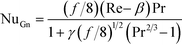
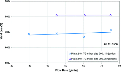
The Grignard-type homogenous synthesis of methyl 2-oxobutanoate (2-MOB, 3) from dimethyl-oxalate (DMO, 1) and ethylmagnesium chloride (2) was used to test several plate reactors, as in Fig. 6. Since the reaction yield is such a strong function of temperature, it is a useful test reaction for understanding localized heat transfer. First, tests were performed in the 240 plate with either one or two injection points to demonstrate the Grignard reaction's high sensitivity to temperature hotspots along the length of the channel. Since there are competitive reactions that are favoured at higher temperatures, it is important to keep the temperature as low as possible. This can be challenging due to the exothermic nature and very fast kinetics of the reaction, causing hotspots to form in the mixing zone of the injection points. Fig. 12 clearly shows that reducing the local concentration of one reactant by injecting it at two points along the channel length increases the overall yield versus one single addition at the plate reactor inlet. In previous work, we have demonstrated that this effect is not a contribution of better mixing but that it is essential to return the fluid temperature near the sink level of the thermal fluid before the next injection point.11 With half of the reactant available, the total heat released near the inlet is about halved, favouring the main reaction over its competitive reaction to produce 5 or 7 from Fig. 6. Haber et al.29 presented a model based on core reaction engineering principles30 to simulate the effect of the multi-injection principle with exothermic reactions which agrees with the observed results here.
 |
| | Fig. 12 Effect of multi-injection for Grignard reaction. | |
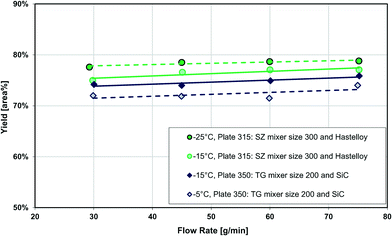
The temperature effect itself can be observed when comparing the same reaction at multiple temperatures for two different plates. Shown in Fig. 13, the reactions with lower overall temperatures resulted in higher yields. Although two separate plates were used with different dimensions, the 10 °C temperature changes resulted in a similar difference in yield. Ultimately, the main factor to control yield remains the multi-injection approach.
 |
| | Fig. 13 Yield vs. flow rate in the 315 and 350 plates at various temperatures. | |
Note that the product yield is only slightly positively correlated with flow rate for the range studied since various counteracting factors are involved. Assuming the reaction is fully mixing controlled, four cases can be depicted: (1) an increase of flow rate favors mixing via higher energy dissipation rate leading to better selectivity (higher yield) for reactions encompassing parallel-consecutive pathways; (2) better mixing also means reagents react in a shorter time (i.e. in a smaller flow path), releasing the heat in a more confined volume which intensifies the hotspot (lowering the yield); (3) the increase of flow rate also increases the reaction heat intensity (power) leading to a larger hotspot; (4) this effect is however somewhat counteracted by the decrease of internal heat transfer resistance. It is this sensitive impact of temperature on selectivity that allows this reaction to be a useful tool for the detection of hotspots in reactors.
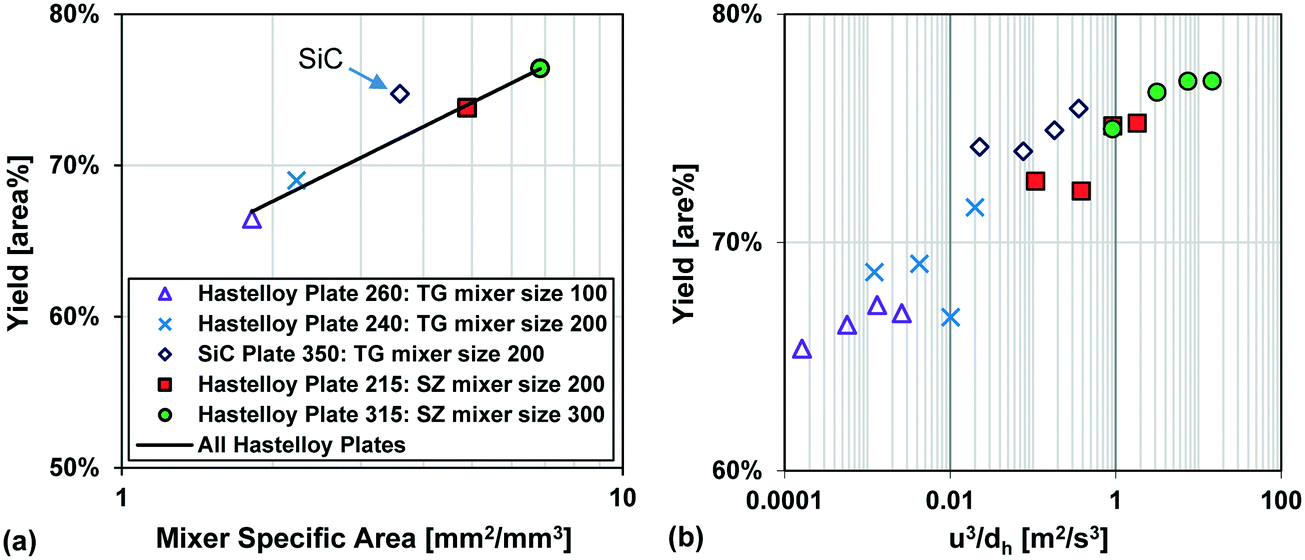
Fig. 13 also compares two different reactor plates in size and material at the same temperature (−15 °C), where the smaller mixer/channel size (Plate 315) seems to have a greater role in enhancing heat transfer than the highly heat-conductive material (Plate 350). The situation is, however, more complex, and it was not possible to get identical plates out of different materials due to various manufacturing methods. One of the issues comes from the fact that when the mixer size is changed, the mixing efficiency is also altered accordingly, and we know from the impact of flow rate that mixing plays a certain role (vide supra). In other words, the mixer specific surface area (a) and the mixing intensity (u3/dh; specific energy dissipation rate) are confounded factors. Fortunately, there were four geometrically different Hastelloy plate reactors that could be tested under identical conditions, and these results are shown in Fig. 14(a) and (b). A linear trend is observed between the metallic plates, with the SiC reactor being clearly an outlier with slightly better performance. Thus, one can now conclude that a plate reactor with a more heat-conductive material and no contact resistance will have better yields.
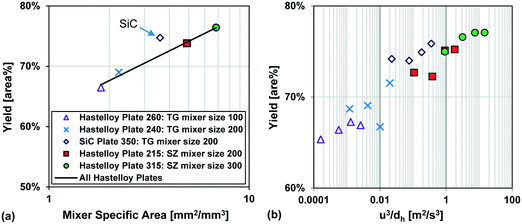 |
| | Fig. 14 (a) Average Grignard reaction yield (at −15 °C) vs. mixer specific area for heat transfer, and (b) Grignard reaction yield (at −15 °C) vs. specific energy dissipation rate (u3/dh). | |
In summary, the selected Grignard test reaction had sufficient resolution to differentiate between plates made from different materials and contact resistances. It was not possible to decouple the effect of geometry from the mixing intensity, as both factors are confounded, and further simulations are required to reach this goal. All in all, the multi-injection principle is the most important factor to control the hotspot, followed by feed concentration9 and temperature. The plate material, the contact resistance, the mixing intensity, and the specific surface area are additional factors with less importance that control the extent (peak magnitude and broadness) of the hotspot.
3.3. Case studies on plate reactor heat transfer capabilities
The purpose of this study was to evaluate the micro-reactors for applications requiring significant heat removal/addition for exo/endothermal reactions. The enhanced wall-to-fluid heat transfer rates provided by micro-reactors' high area-to-volume ratio enable reactions that generate or consume large amounts of heat and the use of more concentrated reactants while greatly reducing the potential of a thermal runaway. The thermal control performance of a reactor as a whole can be expressed using the fourth Damköhler number, DaIV in eqn (11). This dimensionless number represents the ratio of heat-generation, calculated from the reaction rate r, the reaction enthalpy ΔHR and the reactor volume VR, to heat transfer in the reactor, calculated from the overall heat transfer coefficient U, the total area for heat transfer, AHE, and the temperature driving force (|T − TTF|) between the reactive media and thermal fluid used to control the temperature. This number considers all the parameters necessary to optimize the heat transfer in a system. To be satisfactory, this ratio is ideally smaller than one.| | 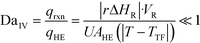 | (11) |
For a given reaction, this can be achieved independently of the reactor scale by lowering the reaction rate using diluted solutions and/or colder temperatures, but these options go against the philosophy of process intensification, and a particular temperature or concentration may be required for yield optimisation. Alternatively, the temperature of the thermal fluid can be adjusted, but this cannot realistically impact DaIV by much more than one order of magnitude.
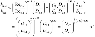
The remaining parametric options, U, AHE and VR, all vary with scale. As discussed, the overall heat transfer coefficient is a function of the internal convective resistance to heat transfer as well as the external resistances in the system (metallic wall conductive and contact resistances, and thermal fluid side convective resistance), which are impacted more so by the system setup rather than scale. The reactor side convection coefficient, hin, will not vary greatly with the scale-up as shown in eqn (12) (a Sieder–Tate-like model that was fit with the results from Fig. 11) and (13). Note that the ratio Q2/Q1 of eqn (13) is changed into a hydraulic diameter ratio using the 3/7th scale-up rule based on constant energy dissipation rate (ε).12
| |  | (12) |
| |  | (13) |
The ratio between the area available for heat transfer, AHE, and the reactor volume, VR, is dependent solely on the Dh of the channels as shown in eqn (14) and (15)
| |  | (14) |
| | 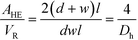 | (15) |
Using the thermal paste case with the 320B RTC; Fig. 10 shows that the overall heat transfer coefficient, U, is roughly equal to 2200 W m−2 K−1. A common heat exchanger design heuristic31 uses 10 K as the minimum approach temperature, |T − Ttf|. Using this value, it is possible to plot the DaIV as a function of the hydraulic diameter for various volumetric heat-generation rate rΔHR. The DaIV of four case studies are evaluated and discussed below. Each case can be classified as a reaction and phase type described by Plouffe et al. based on their kinetics.9 These are displayed on Fig. 15 along with the RTC channel size used in this work (Dh = 909 μm).
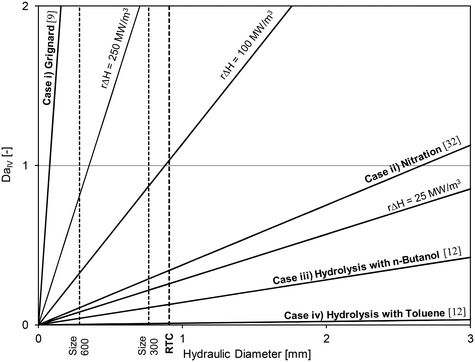 |
| | Fig. 15 Fourth Damköhler number at different heat-generation rates as a function of the sized-up hydraulic diameter and with U = 2200 W m−2 K−1 and |T − Ttf| = 10 K. | |
3.3.1. Case i) Grignard reaction.
The first case study, case i), is the Grignard used in section 3.2. The reaction enthalpy change is approximately 225 kJ mol−1 at −15 °C, and it is reasonable to assume that the reaction is completed within the first 100 milliseconds in the plate reactor (i.e., type A reaction).9 This corresponded to an average reaction rate of ∼5000 mol m−3 s−1 and to a heat-generation rate rΔHR of 1125 MW m−3. The necessary hydraulic diameter to avoid a temperature spike would be below 80 μm – less than the smallest dimension presented in this work. An alternate solution is to distribute the Grignard reactant along the plate reactor volume using multiple inlet ports (multi-injection approach) as previously shown; either with a plate with multiple ports, or multiple plates in series. This multi-injection approach is also possible with conventional technology (i.e., not micro-structured) but with reduced process intensification capabilities.
3.3.2. Case ii) nitration.
The second case study, ii), is the homogenous nitration of salicylic acid using a solution of acetic and nitric acid. The experimental details are described again in ref. 9; the reaction needs to be operated at 65 °C or above to avoid delays associated with the auto-catalytic behaviour of the reaction. At this temperature, the reaction rate was estimated to be ∼230 mol m−3 s−1 (type B), and the reaction enthalpy is 146 kJ mol−1,32 which yielded a heat-generation rate of 33 MW m−3. This is sufficiently low to be operated in micro-reactors, but not necessarily in milli-structures with internal diameters greater than 2.5 mm. Upon scale-up, it would then be best to use an adaptive channel design starting at a small size where the reactants meet and where the heat-generation is high, and progressing into larger channels as the reaction rate decreases, i.e., maintaining the value  constant (multi-scale approach). Typically, a plate with a channel depth starting in the micrometer domain will be selected and increased in size until conventional and readily available heat transfer technology can be used.
3.3.3. Cases iii) and iv) two-phase hydrolysis.
The third and fourth case studies are the liquid–liquid hydrolysis reaction commonly utilized for the characterization of micro-reactors for liquid–liquid mass transfer.12,33–38 While the hydrolysis step itself is not highly exothermic, it is followed by two neutralization steps that result in an overall enthalpy change of about 112 kJ mol−1. The cases here considered the use of a 0.5 mol L−1 solution of the acetate in drop flow operated at an energy dissipation rate of ∼100 m2 m−3. Under homogenous conditions, the initial reaction rate would be 3500 mol m−3 s−1 (type A) and the total heat release rate at around 390 MW m−3. However, these liquid–liquid cases have the distinction of being interphase mass transfer limited, which reduces the observed reaction rate, r. The rate constant is instead equal to the dispersed phase overall volumetric mass transfer coefficient.
Case iii) analyzes the use of n-butanol as the organic solvent. At these conditions, the coefficient Kda was 2.22 × 10⁻¹ s−1,12 which would result in an initial reaction rate of ∼110 mol m−3 s−1 and a heat-generation rate rΔHR of 12.5 MW m−3. Clearly, the results indicate that a micro-structure is no longer needed for the control of reaction heat (as it is safe to operate at a Dh below 7 mm), but rather to increase the rate of mass transfer to increase the overall rate of reaction.
The fourth case considers the use of toluene instead of butanol as the organic solvent. In such case, the coefficient Kda is reduced to 1.66 × 10⁻² s−1 (ref. 12) and the heat-generation rate rΔHR to 0.9 MW m−3.
Low heat-generation rates such as in case iv) can be safely operated in a channel with internal diameters below 90 mm. However, under the flow rates studied in this work, the energy dissipation rate in such a large reactor would be relatively low and the system even more mass transfer limited. The use of a micro-reactor for fast liquid–liquid reactions was necessary to obtain interphase mass transfer rates that are greater than what would be achieved in larger reactors.
Even at high energy dissipation rates using toluene, the acetate hardly transferred to the aqueous phase due to its affinity with the organic solvent. Consequently, large residence times are still needed and cannot realistically be achieved in micro-reactors within reasonable pressure drops. For example, at energy dissipations rates of 100 m2 s−3, the overall volumetric mass transfer coefficient Kda with toluene was such that to obtain a conversion of 90%, a residence time of about 60 seconds would be needed and would result in a pressure drop of 60 bar (ΔP = ρετ).12
In such cases and when heat transfer is not limiting, reactors combining larger channels with an active mixing technique might present a better solution. Active mixing techniques use an external source of energy to agitate the fluids such as mechanical actuators. The energy dissipation rates that can be achieved are generally independent of the overall flow rates, and thus high values can be obtained at the same time as large residence times and low pressure drops. The use of pulsating flow in reactors with baffles39 or without40 have been proven to be useful tools in these cases.
3.3.4. Extension to other micro-reactor systems.
Although the previous analysis used results from a particular metal plate-type micro-reactor system, it can be extended to any other reactor system typically employed in the field of flow chemistry, such as tubular/coiled reactor systems (e.g., offered by Vapourtec Ltd. and Syrris Ltd.), or other plate-type reactors (e.g., Advanced-Flow™ reactor systems offered by Corning® inc.). If an estimation of U is possible for the entire system, then the fourth Damköhler number can be calculated for a given hydraulic diameter, heat of reaction, and temperature difference for heat transfer. Since this estimate of U must take into account all thermal resistances discussed in sections 2.4 and 3.1.2, it is important to consider the entire reactor system's properties such as wall material, external heat transfer fluid and flow rate, as well as any contact resistances between heat transfer surfaces. This approach is a useful tool that can be used to properly select a reactor system or configuration (with or without multi-injection) that will avoid hotspot formation for any temperature-sensitive reaction.
4. Conclusions
Non-reactive heat transfer experiments were performed in the A6-sized FlowPlate® system manufactured by Ehrfeld Mikrotechnik. For a residence time channel with Reynolds numbers ranging from 400–2000, the internal Nusselt number was fit to a Gnielinski-like model. This was deemed appropriate due to the curvature in the channels. The channel's curvature could form chaotic eddies at relatively low Reynolds numbers, which agreed with the observed friction factor results. The Nusselt number also correlated with Reynolds to the power of 0.85 ± 0.12, which is similar to that of the turbulent Sieder–Tate correlation (0.8); further confirming the use of a model in transitional/turbulent flow over laminar flow. The external resistances to heat transfer were also studied in this system; specifically, the HTF flow rate and the contact resistance between the HTF plate and RTC plate. The largest contributor to the resistance of heat transfer was shown to be the contact resistance, which could significantly reduce the external resistance (by approximately 70%) using a silver-based thermal paste.
A test reaction, the synthesis of methyl 2-oxobutanoate using dimethyl-oxalate and the Grignard reagent ethylmagnesium chloride, was also presented as a means to differentiate localized heat transfer characteristics in various micro-mixer shapes, materials, injection ports, and scales. Due to the fast reaction kinetics, high exothermicity, and the increased selectivity for the desired product at lower temperatures, this reaction allows for a semi-quantitative comparison of hotspot formation in different plate reactors when comparing total yields. It was shown that the Grignard reaction can be used as a sensitive tool to compare different reactors when the specific heat transfer parameters are not fully known. A multi-injection approach was shown to be the most effective method for reducing the magnitude of hotspot formation, thereby increasing the reaction yield. Additionally, increasing the specific area of a mixer geometry led to higher yields due to increased wall-to-fluid heat transfer.
Lastly, four case studies were analyzed based on the fourth Damköhler number to evaluate what maximum channel diameter would allow sufficient heat removal based on the overall heat transfer coefficients found experimentally. With a known reaction rate and heat of reaction, it is possible to select a suitable channel size. This analysis is a useful addition to the toolbox developed by Plouffe et al.9 when selecting a proper reactor system for a given application and can be applied to any flow chemistry system where the overall heat transfer coefficient can be estimated.
5. Nomenclature
| Symbols |
|
[Units] |
| General |
|
|
a
|
Specific area (single phase) or specific interfacial area (biphasic) |
[m2 m−3] |
|
A
HE
|
Area available for heat transfer |
[m2] |
|
c
p
|
Heat capacity of fluid |
[J kg−1 K−1] |
|
d
|
Contraction depth |
[m] |
|
D
h
|
Hydraulic diameter at contraction (2wd/(w + d)) |
[m] |
| DaIV |
Damköhler number = |rΔHR|·VR/UAHE(|T − TTF|) |
[—] |
| Dn |
Dean number = Re(Dh/2Rc)1/2 |
[—] |
|
f
|
Friction factor (Darcy–Weisbach definition) |
[—] |
|
f
c
|
Chaotic term in friction factor |
[—] |
|
f
l
|
Laminar term in friction factor |
[—] |
|
|
Local convective heat transfer coefficient |
[W m−2 K−1] |
|
H
A
|
Organic/aqueous concentration distribution coefficient |
[—] |
| ΔHr |
Reaction enthalpy change |
[J mol−1] |
| HTF |
Heat transfer fluid |
|
|
k
|
Thermal conductivity |
[W m−1 K−1] |
|
K
d
|
Overall convective mass transfer coefficient |
[m s−1] |
|
l
|
Reactor length |
[m] |
|
ṁ
|
Mass flow rate |
[kg s−1] |
| MTR |
Mix-then-reside reactor |
|
| Nu |
Nusselt number = hDh/kf |
[—] |
| ΔP |
Pressure loss across reactor length |
[Pa] |
| Pr |
Prandtl number = cpμ/kf |
[—] |
|
q
|
Heat transferred |
[W] |
|
Q
|
Volumetric flow rate |
[m3 s−1] |
|
r
|
Reaction rate |
[mol s−1] |
|
R
|
Radius of curvature |
[m] |
|
R
cond
|
Resistance to heat transfer via conduction |
[K W−1] |
|
R
contact
|
Resistance to heat transfer via contact between the plates |
[K W−1] |
|
R
conv
|
Resistance to heat transfer via convection |
[K W−1] |
|
R
ext
|
External resistance to heat transfer |
[K W−1] |
|
R
tot
|
Total resistance to heat transfer in the system |
[K W−1] |
| Re |
Reynolds number = ρuDh/μ |
[—] |
| RTC |
Residence time channel |
|
|
T
|
Temperature |
[°C or K] |
|
t
|
Wall thickness |
[m] |
| TG |
Tangential mixer |
|
|
u
|
Superficial velocity of the fluid at the contraction |
[m s−1] |
| U |
Overall heat transfer coefficient |
[W m−2 K−1] |
| V |
Volume |
[m3] |
| w |
Contraction width |
[m] |
| |
| Greek Symbols |
|
α
|
Aspect ratio (w/d) |
[—] |
|
β
|
1st fitted parameter for Gnielinski-type model |
[—] |
|
γ
|
2nd fitted parameter for Gnielinski-type model |
[—] |
|
ε
|
Average rate of energy dissipation (ΔP/ρτ) |
[m2 s−3] |
|
μ
|
Dynamic viscosity |
[Pa s] |
|
ρ
|
Density |
[kg m−3] |
|
τ
|
Average residence time |
[s] |
| |
| Subscripts |
|
| 1,2 |
Two different scales |
|
| c |
Cold stream |
|
| DB |
Dittus–Boelter |
|
| f |
Fluid |
|
| Gn |
Gnielinski |
|
| h |
Hot stream |
|
| HE |
Heat exchange |
|
| i |
Measured at inlet |
|
| in |
Inner channel side (in this case RTC or MTR side) |
|
| LM |
Log mean |
|
| ME |
Mixing element |
|
| o |
Measured at outlet |
|
| out |
Outer channel side (in this case HTF side) |
|
| R |
Reactor side |
|
| rxn |
Reaction |
|
| s |
Conditions at the wall surface |
|
| ST |
Sieder–Tate |
|
| TF |
Transfer fluid |
|
| tot |
Total |
|
| w |
Across the wall |
|
Conflicts of interest
There are no conflicts of interest to declare.
Acknowledgements
The authors would like to thank the Natural Sciences and Engineering Research Council of Canada, including the CREATE program in Continuous Flow Science, and Lonza AG for their financial contribution. Also, Ehrfeld Mikrotechnik is acknowledged for the reactor manufacturing.
References
- N.-T. Nguyen and Z. Wu, Micromixers—a review, J. Micromech. Microeng., 2005, 15, R1–R16, DOI:10.1088/0960-1317/15/2/R01.
- M. N. Kashid and L. Kiwi-Minsker, Microstructured Reactors for Multiphase Reactions: State of the art, Ind. Eng. Chem. Res., 2009, 48, 6465–6485, DOI:10.1021/ie8017912.
- N. Kockmann, M. Gottsponer and D. M. Roberge, Scale-up concept of single-channel microreactors from process development to industrial production, Chem. Eng. J., 2011, 167, 718–726, DOI:10.1016/j.cej.2010.08.089.
- V. Kumar, M. Paraschivoiu and K. D. P. Nigam, Single-phase fluid flow and mixing in microchannels, Chem. Eng. Sci., 2011, 66, 1329–1373, DOI:10.1016/j.ces.2010.08.016.
- N. Kockmann and D. M. Roberge, Scale-up concept for modular microstructured reactors based on mixing, heat transfer, and reactor safety, Chem. Eng. Process., 2011, 50, 1017–1026, DOI:10.1016/j.cep.2011.05.021.
- P. S. Lee and S. V. Garimella, Thermally developing flow and heat transfer in rectangular microchannels of different aspect ratios, Int. J. Heat Mass Transfer, 2006, 49, 3060–3067, DOI:10.1016/j.ijheatmasstransfer.2006.02.011.
-
S. Kandlikar, S. Garimella, D. Li, S. Colin and M. R. King, Heat Transfer and Fluid Flow in Minichannels and Microchannels, Elsevier Ltd., Kidlington, Oxford, 2nd edn, 2014, DOI:10.1016/B978-0-08-098346-2.00003-X.
- I. Rossetti and M. Compagnoni, Chemical reaction engineering, process design and scale-up issues at the frontier of synthesis: Flow chemistry, Chem. Eng. J., 2016, 296, 56–70, DOI:10.1016/j.cej.2016.02.119.
- P. Plouffe, A. Macchi and D. M. Roberge, From batch to continuous chemical synthesis-a toolbox approach, Org. Process Res. Dev., 2014, 18, 1286–1294, DOI:10.1021/op5001918.
- P. Barthe, C. Guermeur, O. Lobet, M. Moreno, P. Woehl and D. M. Roberge,
et al., Continuous multi-injection reactor for multipurpose production - Part I, Chem. Eng. Technol., 2008, 31, 1146–1154, DOI:10.1002/ceat.200800132.
- D. M. Roberge, N. Bieler, M. Mathier, M. Eyholzer, B. Zimmermann and P. Barthe,
et al., Development of an industrial multi-injection microreactor for fast and exothermic reactions - Part II, Chem. Eng. Technol., 2008, 31, 1155–1161, DOI:10.1002/ceat.200800131.
- P. Plouffe, M. Bittel, J. Sieber, D. M. Roberge and A. Macchi, On the scale-up of micro-reactors for liquid–liquid reactions, Chem. Eng. Sci., 2016, 143, 216–225, DOI:10.1016/j.ces.2015.12.009.
-
F. P. Incropera, D. P. DeWit, T. L. Bergman and A. S. Lavine, Fundamentals of Heat and Mass Transfer, John Wiley & Sons, Inc., Jefferson City, 7th edn, 2011 Search PubMed.
- G. L. Morini, Single-phase convective heat transfer in microchannels: A review of experimental results, Int. J. Therm. Sci., 2004, 43, 631–651, DOI:10.1016/j.ijthermalsci.2004.01.003.
-
M. E. Steinke and S. G. Kandlikar, Single-phase liquid heat transfer in microchannels, in: 3rd Int. Conf. Microchannels Minichannels, 2005, DOI:10.1115/ICMM2005-75114.
-
W. M. Kays and M. E. E. Crawford, Convective Heat and Mass Transfer, McGraw-Hill, Boston, 4th edn, 2005 Search PubMed.
-
N. Kockmann, Transport Phenomena in Micro Process Engineering, Springer Berlin Heidelberg, Berlin, Heidelberg, 2008, DOI:10.1007/978-3-540-74618-8.
- W. R. Dean, Note on the motion of fluid in a curved pipe, Philos. Mag., 1927, 4, 208–223 CrossRef.
- W. R. Dean, The stream-line motion of fluid in a curved pipe, Philos. Mag., 1928, 5, 673–695 CrossRef.
- F. Jiang, K. S. Drese, S. Hardt, M. Kupper and F. Schonfeld, Helical flows and chaotic mixing in curved micro channels, AIChE J., 2004, 50, 2297–2305, DOI:10.1002/aic.10188.
- F. Schönfeld and S. Hardt, Simulation of helical flows in microchannels, AIChE J., 2004, 50, 771–778, DOI:10.1002/aic.10071.
- G. Gauthier, P. Gondret, H. Thomé and M. Rabaud, Centrifugal instabilities in a curved rectangular duct of small aspect ratio, Phys. Fluids, 2001, 13, 2831–2834, DOI:10.1063/1.1400136.
-
Perry's Chemical Engineers' Handbook, ed. R. H. Perry, D. W. Green and J. O. Maloney, McGraw-Hill, New York, 8th edn, 2007 Search PubMed.
- T. Adams, M. Dowling, S. Abdel-Khalik and S. Jeter, Applicability of traditional turbulent single-phase forced convection correlations to non-circular microchannels, Int. J. Heat Mass Transfer, 1999, 42, 4411–4415, DOI:10.1016/S0017-9310(99)00102-7.
- T. M. Adams, S. I. Abdel-Khalik, S. M. Jeter and Z. H. Qureshi, An experimental investigation of single-phase forced convection in microchannels, Int. J. Heat Mass Transfer, 1998, 41, 851–857, DOI:10.1016/S0017-9310(97)00180-4.
-
Haynes International, HASTELLOY® C-22® Alloy, 2015, http://www.haynesintl.com/alloys/alloy-portfolio_/Corrosion-resistant-Alloys/HASTELLOY-C-22-.aspx (accessed September 21, 2016) Search PubMed.
-
McMaster-Carr, Electrically and Thermally Conductive Grease, 2016, http://www.mcmaster.com/#1219k59/ (accessed September 21, 2016).
- J. Pátek, J. Hrubý, J. Klomfar, M. Součková and A. H. Harvey, Reference Correlations for Thermophysical Properties of Liquid Water at 0.1 MPa, J. Phys. Chem. Ref. Data, 2009, 38, 21, DOI:10.1063/1.3043575.
- J. Haber, M. N. Kashid, A. Renken and L. Kiwi-Minsker, Heat management in single and multi-injection microstructured reactors: Scaling effects, stability analysis, and role of mixing, Ind. Eng. Chem. Res., 2012, 51, 1474–1489, DOI:10.1021/ie201158a.
-
O. Levenspiel, Chemical Reaction Engineering, Wiley, New York, 1999 Search PubMed.
-
J. R. Couper, W. R. Penney, J. R. Fair and S. M. Walas, Chemical Process Equipment: Selection and Design, Elsevier, Waltham MA, 3rd edn, 2012 Search PubMed.
- R. Andreozzi, M. Canterino, V. Caprio, I. Di Somma and R. Sanchirico, Batch salicylic acid nitration by nitric acid/acetic acid mixture under isothermal, isoperibolic and adiabatic conditions, J. Hazard. Mater., 2006, 138, 452–458, DOI:10.1016/j.jhazmat.2006.05.104.
- B. Ahmed-Omer, D. Barrow and T. Wirth, Effect of segmented fluid flow, sonication and phase transfer catalysis on biphasic reactions in capillary microreactors, Chem. Eng. J., 2008, 135, S280–S283, DOI:10.1016/j.cej.2007.07.017.
- B. Ahmed, D. Barrow and T. Wirth, Enhancement of reaction rates by segmented fluid flow in capillary scale reactors, Adv. Synth. Catal., 2006, 348, 1043–1048, DOI:10.1002/adsc.200505480.
- V. D. Parker, Instantaneous rate constants in physical organic chemistry: Application to acyl transfer reactions of p-nitrophenyl acetate to hydroxide ion, J. Phys. Org. Chem., 2006, 19, 714–724, DOI:10.1002/poc.1064.
- P. Plouffe, D. M. Roberge and A. Macchi, Liquid–liquid flow regimes and mass transfer in various micro-reactors, Chem. Eng. J., 2016, 300, 9–19, DOI:10.1016/j.cej.2016.04.072.
- P. Plouffe, D. M. Roberge, J. Sieber, M. Bittel and A. Macchi, Liquid–liquid mass transfer in a serpentine micro-reactor using various solvents, Chem. Eng. J., 2016, 285, 605–615, DOI:10.1016/j.cej.2015.09.115.
- E. Mielke, D. M. Roberge and A. Macchi, Microreactor mixing-unit design for fast liquid—liquid reactions, J. Flow Chem., 2016, 6, 279–287, DOI:10.1556/1846.2016.00026.
- J. R. McDonough, A. N. Phan and A. P. Harvey, Rapid process development using oscillatory baffled mesoreactors – A state-of-the-art review, Chem. Eng. J., 2015, 265, 110–121, DOI:10.1016/j.cej.2014.10.113.
- S. S. Mongeon, D. M. Roberge, M. Bittel, P. Elsner and A. Macchi, Liquid–Liquid Mass Transfer in an Oscillatory-Flow Mesoscale Coil Reactor without Baffles, Org. Process Res. Dev., 2016, 20(4), 733–741 CrossRef CAS.
|
| This journal is © The Royal Society of Chemistry 2017 |
Click here to see how this site uses Cookies. View our privacy policy here. 
 a,
Patrick
Plouffe
a,
Patrick
Plouffe


 constant (multi-scale approach). Typically, a plate with a channel depth starting in the micrometer domain will be selected and increased in size until conventional and readily available heat transfer technology can be used.