 Open Access Article
Carbon black functionalized stretchable conductive fabrics for wearable heating applications†
Lakshitha R. Pahalagedaraa,
Induni W. Siriwardanea,
Nadeeka D. Tisseraa,
Ruchira N. Wijesenaa and
K. M. Nalin de Silva *ab
*ab
aSri Lanka Institute of Nanotechnology (SLINTEC), Nanotechnology and Science Park, Pitipana, Homagama, Sri Lanka. E-mail: kmnd@chem.cmb.ac.lk
bDepartment of Chemistry, University of Colombo, Colombo 03, Sri Lanka
First published on 31st March 2017
Abstract
There is an increasing interest on robust electrically conductive textiles with light weight and flexibility to meet the applications in wearable electronics. Current challenge is to fabricate such structures with feasible application strategies that can be readily scalable and provide higher mechanical stability of the conductive media on the textile matrix to withstand constant stretch and shear forces. We report a strategy to address these challenges, by using a “screen printing process” employing conductive carbon black ink. We produced conductive fabrics with liner resistance of less than 71 Ω cm−1. These textile materials showed stable conductivity up to 25% strain. Microscopic studies revealed that at strains lower than 25%, percolation pathways in the conductive media increases resulting lowering of the liner resistance. However, further stretching of over 25% resulted increase of resistance due to separation of conductive pathways. Ohmic heating application of the resulted fabrics showed fast response rate and no significant hysteresis. The conductive print was stable over long period of heating over number of cycles. These feasible conductive fabric fabrication pathways can provide new avenues in designing and manufacturing of wearable heat management and electronic applications.
1. Introduction
Since the birth of nanotechnology carbon nanomaterials such as carbon black, graphene oxide, chemically reduce graphene oxide, carbon nanofibers and carbon nanotubes (CNT) are realized as effective candidates in wearable electronics due to their unique structure dependent high electric conductive property.1–7 Electricity insulating natural and synthetic fibers consisting of cotton, nylon, polyester, elastomers or wool polymers are embedded with carbon nanomaterials using different methodologies as reported in many research studies, to achieve fiber and fiber assembly (fabrics and yarns) based electric and electronic properties.8–12 In these studies a variety of wearable textile material are proposed. The proposed applications are not limited to wearable sensors, actuators, super capacitors,13–17 display devices,18,19 memory and energy devices.20–23 Among them, carbon nanomaterials coated textiles were also used as light weight heating devices operates at low voltages which are applicable as self-heating textiles.24In many research studies carbon nanotubes (CNT) are realized as an effective candidate for textile based wearable heaters due to their superior thermal and electric properties.25 Cotton textiles functionalized by dip coating of CNT showed a surface temperature of 45 °C upon an application of 20 V along a 2 cm distance.26 Carbon black is gaining the popularity among wearable textiles as a comparatively low cost material to CNT. In one research study carbon activated cotton thread was used to harvest electrostatic energy from environment.27 In another research study nontoxic inexpensive active carbon was printed on a textile as a flexible energy storage device.28 Moreover, in a similar study, more expensive reduced graphene oxide (rGO) has been used to fabricate conductive fabric materials and its thermal behaviour has been analyzed. However, the average temperature that it was heated up to is 36 °C even at voltage which is high as 32.5 V.29
To this end flexible wearable heating textiles are challenged with economic processability, fastness to multiple washing and rubbing cycles, rapid heating at low input power, and thermal stability over time. Also for practical comfort against wearing, flexibility and stretch ability of these are of paramount important. To the best of our knowledge little or no work have been made on electrical heating behaviour of carbon black printed cotton, nylon and polyester textiles with aforementioned functional properties. In this study we have established a simple screen printing methodology designed to print a carbon black paste over a wide dimension of textiles (cotton, nylon, polyester and nylon/spandex blend) to achieve electric heating property. Carbon black printed polyester fabrics showed a surface temperature of 65 °C respectively along 4 cm distance upon an application of 15 V with a superior thermal stability over time. The thickness of the polyurethane matrix printed on the conductive area was well engineered to allow for stretchability, and a rating of 4.5 and 4.5 for 10 wet and 25 dry rubbing cycles respectively. The overall analysis of the carbon black and polyurethane printed textiles strongly suggest the inherent electric heating, flexibility and mechanical properties of carbon black and polyurethane can be used on a wide dimension of textile for flexible wearable textile heaters.
2. Experimental
2.1 Formulation of carbon black (CB) dispersion
The CB dispersion was prepared by stirring a mixture containing 20% (w/w) CB and 10% (w/w) surfactant (dodecyldimethylammonium bromide, DDAB or sodium dodecyl sulfate, SDS) in water at room temperature for 1 hour and then sonicating the mixture in a Grant bath type ultrasonicator, operating at 35 W power output at the frequency of 50–60 Hz for 2 h.The dispersions of carbon black powder in aqueous medium were investigated by using cationic surfactant DDAB and anionic surfactant SDS. The zeta potential was measured by a Malvern Zetasizer NanoZs analyzer. The zeta potentials of dispersions were measured at room temperature and at pH = 7.
Dynamic light scattering of the CB dispersions were performed at room temperature using a Malvern Zetasizer NanoZs compact scattering spectrophotometer with a 4.0 mW He–Ne laser (633 nm wavelength) at a scattering angle of 170°.
2.2 Construction of CB treated flexible conductive fabrics
Swatches of fabric (FAB) with the dimensions of 4 cm × 3 cm were cut and aligned for screen printing. The screen printing frame was a nylon mesh with filament spacing approximately 0.3 mm apart. The screen was placed over the fabric and the SDS stabilized CB dispersion was spread to smoothly apply the carbon across the fabric along the wale direction of the fabric. This process was repeated 3 times to ensure full penetration of carbon through the yarns. All swatches were dried in an oven at 130 °C for 2 h to remove any residual water (CB@FAB).The PU solution (10% w/w PU in commercial grade mineral spirits) was printed on oven dried CB printed fabric using the same printing method and repeated for 2 times. The PU printed fabrics (PU@CB@FAB) were dried in an oven at 130 °C for 5 minutes. The composition of the final material (PU@CB@FAB) was calculated using a simple gravimetric procedure where the weights of the FAB, CB@FAB, and PU@CB@FAB were measured and the weight of each component was calculated.
2.3 Characterization of CB treated conductive fabrics
Morphological characteristics of untreated fabric, CB@FAB, and PU@CB@FAB were studied using a Hitachi SU6600 field emission scanning electron microscope.Atomic Force Microscopic (AFM) analysis of polyester fabric and CB printed polyester fabric was performed using a Park System AFM. AFM images were captured using an XE-100 microscope. The measurements were performed in air at room temperature using non-contact mode, with Si tips of the 1650–00 type scanning at a rate of 0.5 Hz at room temperature.
TGA analysis was performed in an air atmosphere using a STD Q600 analyser. The temperature range was 25–800 °C and the heating ramp rate was 5 °C min−1.
Mechanical properties such as tensile strength, elastic modulus and elongation at break between untreated fabric and PU@CB@FAB were compared at a strain rate of 5 mm min−1 using an Instron Tensile test rig. Thickness of each film was measured using digital micrometer screw-gauge (Mitutoyo, 0.001 mm resolution) prior to testing.
The ATR-FTIR studies were carried out in order to study the successful incorporation of conductive material on to the fabric. A Brucker vertex 80 FTIR instrument was used over the wavenumber region of 4000–800 cm−1 with 32 scans at a resolution of 4 cm−1.
2.4 Conductivity studies of CB treated fabrics
The conductivity and the maximum temperature reached due to ohmic heating were measured by varying the number of cycles (up to 3 cycles) of CB layers printed on the fabric. A final PU layer was applied on the last CB layer. The current–voltage characteristics were studied for two widths of CB functionalized fabric swatches with dimensions of 4 cm × 1.5 cm and 4 cm × 3 cm. Effect of stretching on conductivity was studied by measuring the resistance at different percent displacements from the original length of PU@CB@FAB. The displacement was varied from 0–50%. The mechanical stretching was applied using an Instron Tensile test rig. The applicability of the present method for the fabrication of conductive fabrics on different types of fabric materials was tested by applying the CB dispersion and PU layer on cotton, polyester–spandex, and nylon fabrics. The conductivity across the fabric swatches were measured and compared.2.5 Studies of conductive fabrics for wearable heating applications
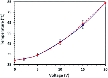
A voltage was applied across the fabric and it was varied from 0–20 V. The temperature on the fabric surface was measured using an IR camera (FLIR i7) and the plots were made as a function of the applied DC input voltages of 0, 2.5, 5, 10, 15, and 20 V. Moreover, the surface temperature of the fabric was measured while decreasing the applied voltage in order to study whether there is a hysteresis present. The time-dependent temperature profiles were studied under a constant applied voltage of 15 V. The applied voltage was held for 60 min, in order to study the consistency of the heating effect and thermal stability of the PU@CB@FAB. The operational stability and repeatability study for CB based fabric heaters was performed as a function of time under a heat cycle. In a single heat cycle a 15 V voltage was applied for 100 s across the fabric and then there was no voltage applied for another 100 s. The rates of heating and cooling response and the maximum steady state temperature were measured.2.6 Colour fastness tests on CB based conductive fabrics
The test specimen were placed on the base of the crock meter (Infinity RS-8318B) so that it rested flat with its long dimension in the direction of rubbing. A 5 × 5 cm2 dry undyed test cloth was mounted over the end of the finger which projects downward from the weighed (9 N) sliding arm. The finger was lowered onto the test specimen and it was crocked back and forth 50 times by making 25 complete turns (AATCC test method 8-2007). Wet fastness of the test cloth was performed using the same way with a moistened 5 × 5 cm2 dry undyed test cloth and crocked back and forth 20 times by making 10 complete turns. Wash fastness test was performed for PU@CB@FAB. The washing temperature was maintained at 40 °C and the spin speed was 645 rpm. The dry load to detergent ratio was 400![[thin space (1/6-em)]](https://www.rsc.org/images/entities/char_2009.gif) :
:![[thin space (1/6-em)]](https://www.rsc.org/images/entities/char_2009.gif) 9 and the total washing time was 30 minutes. The washed fabric swatch was dried at 73 °C for 50 minutes with 10 minute intervals. The resistance value of the washed and dried PU@CB@FAB swatch was then measured and the whole procedure was triplicated.
9 and the total washing time was 30 minutes. The washed fabric swatch was dried at 73 °C for 50 minutes with 10 minute intervals. The resistance value of the washed and dried PU@CB@FAB swatch was then measured and the whole procedure was triplicated.
3. Results and discussion
3.1 Construction and characterization of CB impregnated conductive fabrics
The zeta potential analysis of formulated CB gave a positive potential of 17 mV when the cationic surfactant DDAB was used (Fig. S1a†).30 On the other hand, when the anionic surfactant SDS was used a negative potential of 36 mV (Fig. S1b†) was observed.31 This difference is due to the charge of the surfactants used in the process.32 The reverse in sign of the zeta potential demonstrates that surfactants could disperse and stabilize the carbon black particles by electrostatic or steric forces.33 However, the zeta potential or the surface charge greatly influences particle stability in suspension through the electrostatic forces between CB particles where higher zeta potential values indicate a greater the surface stability due inter particle repulsion. Therefore, the presence of an anionic surfactant stabilizes the CB suspension in an aqueous medium more than that of a cationic surfactant does.31The volume average mean particle size and size distribution of CB suspensions prepared in the presence of DDAB and SDS were analyzed using dynamic light scattering (DLS). As shown in Fig. S2a,† the size distribution profile of CB suspension with DDAB consist of two broad peaks, a short one around 180 nm (2%) and a large one with a mean diameter of 1208 nm (98%), suggesting that the individual CB particles have been aggregated together forming large aggregate particles due to low stability of CB in the aqueous medium. On the other hand, the size distribution curve in the presence of SDS represents a narrow size distribution with a mean particle size of 179 nm (Fig. S2b†). According to zeta potential analysis, and particle size distribution analysis it was determined that the anionic surfactant, SDS would be more suitable over the cationic surfactant, DDAB for the preparation of a stable CB suspension.32,33
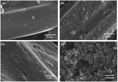
The surface morphology of the bare polyester fabric (FAB) and a CB treated polyester fabric (CB@FAB) and PU protected CB treated polyester (PU@CB@FAB) is compared in SEM images given in Fig. 1a–c. CB nanoparticles have been uniformly coated on the polyester fabric. The CB particles are in the size range of 40–60 nm where majority of the particles are nearly 50 nm in size (Fig. 1d). The PU layer act as a protective matrix, without disturbing the conductivity of CB coating. Fig. S3a and b† compares the yarn morphology of CB@FAB with that of a PU@CB@FAB, where it is seen that the PU matrix keeps the CB coated yarns more intact by acting as a gap filler compared to the one without PU coating.
Morphology of the CB printed polyester fabric was further analyzed using non-contact mode AFM scanned at 0.5 Hz. AFM topographical image of the untreated polyester yarn surface revealed a relatively smoother surface profile (Fig. 2a). The line profile of the image showed the maximum height different along the yarn surface is in 8–16 nm which is due to deposited debris during fabric finishing processes. CB printed polyester surface showed a layer of coating present on the yarn surface (Fig. 2c). The coating on yarn surface has masked the uniform smooth nature of the pristine polyester. According to the analysis, the coating comprises of nano scale surface roughness due to the presence of spherical CB particles. Line profile of the image (Fig. 2c) showed the average height of these agglomerates is 20 nm. For CB printed polyester the coating was applied as a thin film on the yarn surface with a spherical particle deposition according the information obtained using AFM micrograph (Fig. 2c).
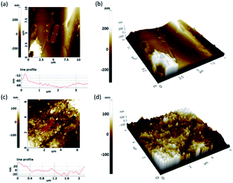 | ||
| Fig. 2 (a) AFM topographical images and line profile (b) 3D topographical AFM image of FAB and (c) AFM topographical images and line profile (d) 3D topographical AFM image of PU@CB@FAB. | ||
When compared the 3D topographical AFM images of the pristine polyester yarn surface and CB printed yarn surface (Fig. 2b and d, respectively) it is clear that printed surface consist of an agglomerated particles of carbon black with a uniform thickness along the length of the yarn. Fig. S4a† shows the TGA profiles of bare polyester fabric, SDS and dried (solvent free) PU used for this study, whereas Fig. S4b† shows the TGA profiles of dried solid CB-SDS suspension and the PU@CB@FAB.
In analyzing the TGA profile of SDS, it is seen that the decomposition of SDS completes by 285 °C, while about 24% of its weight remains even after 800 °C. On the other hand, polyurethane used in this study completely degrades by 530 °C. The bare polyester fabric thermally degrades in two steps: first an 82% weight loss around 440 °C and then an 18% of weight loss around 527 °C, with no residue remaining after 600 °C. Further, the thermal degradation of the CB-SDS occurs in two steps: the degradation of SDS around 250 °C and the decomposition of CB particles around 550 °C. Hence, it seems that the surfactant molecules has lowered the thermal stability of carbon black. Moreover, the decomposition profile of PU@CB@FAB contains the weight loss corresponding to the SDS. However, according to the graph, the weight loss of PU and CB in the printed polyester material could not be clearly distinguished with that of CB. Also it is evident that due to the formation of a thin film, the thermal stability of carbon black has been further reduced on the polyester fabric. Even though, the thermal stability of the polyester fabric has been reduced by the incorporation of CB, both CB@FAB and PU@CB@FAB can withstand a temperature up to around 200 °C, without any considerable degradation. Hence, the TGA analysis confirms the applicability of this article for ohmic heating applications, where both CB@FAB and PU@CB@FAB can be heated up to around 200 °C, without any decomposition happening to the treated fabric.
The comparison of FT-IR spectra of FAB, CB@FAB and PU@CB@FAB shows that they are consisting of more or less similar functional groups (Fig. S5†). The ester group functionalities are prominently present in all three spectra. The peak around 1715 cm−1 is corresponding to the stretching vibrations of ester carbonyl group,34,35 whereas the three strong peaks present region of 1010–1240 cm−1 could be attributed to the stretching vibrations of ester C–O bond34,35 in polyester. The peaks corresponding to the stretching vibrations of long alkane chains34 of polyester could be identified in the region of 2800–3500 cm−1, whereas those of alkyl bending modes34 are present in the region of 1350–1450 cm−1, in all three spectra. However, the two peaks present in the region of 1570–1620 cm−1 in both CB@FAB and PU@CB@FAB, which could be attributed to the stretching vibrational modes of aromatic C![[double bond, length as m-dash]](https://www.rsc.org/images/entities/char_e001.gif) C bonds,36 are not present in the spectrum of bare fabric (FAB). These vibrational stretching modes could be attributed as to be originating from the aromatic C
C bonds,36 are not present in the spectrum of bare fabric (FAB). These vibrational stretching modes could be attributed as to be originating from the aromatic C![[double bond, length as m-dash]](https://www.rsc.org/images/entities/char_e001.gif) C present in carbon black. In addition, there are no clear peaks visible in both CB@FAB and PU@CB@FAB, which could be thought as to be corresponding to any newly formed bonds between CB and FAB. Therefore, as evident by the FTIR analysis, it could be concluded that there is no chemical bond formation happened between the fabric and carbon black particles, instead only a physical attraction exists.
C present in carbon black. In addition, there are no clear peaks visible in both CB@FAB and PU@CB@FAB, which could be thought as to be corresponding to any newly formed bonds between CB and FAB. Therefore, as evident by the FTIR analysis, it could be concluded that there is no chemical bond formation happened between the fabric and carbon black particles, instead only a physical attraction exists.
The mechanical testing results were used to analyze the Young's modulus, elongation and tensile strength for FAB and PU@CB@FAB (Fig. S6†). According to the obtained stress–strain curves, the untreated fabric withstands a slightly higher stress (22 MPa) compared to PU@CB@FAB (19.5 MPa). On the other hand, the treated fabric withstands a greater strain (0.55 mm mm−1) compared to the untreated fabric (0.48 mm mm−1) suggesting that both the CB and PU coatings on the treated fabric enhance its stretchability. Moreover, the calculated modules for the untreated fabric is higher than that of the treated fabric making the latter much more flexible compared to its untreated counterpart. The enhanced flexibility and stretchability induced by the PU coating is due to the properties of the starting compounds used to produce the polyurethane.
The PU coating further acts as a soft and light, protective matrix the CB treated fabric increasing the fabric abrasion resistivity. The crocking test method is designed to determine the amount of colour transferred from the surface of coloured textile materials to other surfaces due to the process of rubbing (Fig. S7a and b†). However, because of the PU matrix, PU@CB@FAB showed a very high dry and wet crocking fastnesses of grade 4.5. The resistance was increased only up to 75 Ω cm−1 after 25 abrasion (AATCC test method 8-2007) cycles with respect to its original value of 71 Ω cm−1. The resistance of PU@CB@FAB was slightly increased (14 ± 2%) after first washing cycle due to the loss of loosely bound CB, while there was no significant change in the resistance (2 ± 0.5%) after second washing cycle. This reflects that the conductive fabrics presented in this study are washable and show high wash fastness properties. Therefore, by carefully controlling the concentration of PU, the flexibility, stretchability, abrasion resistivity and wash fastness could be greatly improved.
3.2 Carbon black treated conductive fabrics
The CB treated polyester fabric demonstrate excellent electrical and mechanical properties. Fig. S8† shows the resistance measurements of polyester fabric treated with CB in different ways. Interestingly, the conductance performance of PU@CB@FAB (71 ± 4 Ω cm−1) does not vary a lot from that of CB@FAB (66 ± 3 Ω cm−1) suggesting that PU is a good candidate as a matrix in the CB layer of CB@FAB. Upon increasing the number of CB layers on the fabric, the resistance decreases as a result of increasing the number of conductive paths. However, in this study we proceeded with having a PU coating on top of a single CB layer in order to retain the fabrics original hand feel and strength while improving its flexibility and stretchability.Fig. 3a shows the current–voltage (I–V) characteristics studied for two different widths of PU@CB@FAB with print dimensions of 4 cm × 3 cm (DW) and 4 cm × 1.5 cm (DN). A linear relationship between the current and voltage could be obtained across the fabrics.
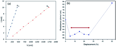 | ||
| Fig. 3 (a) (I–V) measurements of CB treated fabrics with different widths and (b) conductivity of PU@CB@FAB under tensile strain. | ||
Here, two different resistance values with a significant variation corresponding to their widths were observed, suggesting that the electrical resistance of the CB treated fabric is inversely proportional to its width. This study signifies the improvements in electrical conductive pathways available for the charge flow. Moreover, the linearity of the I–V curve demonstrates that the material acts as an ideal resistor over the voltage range studied.
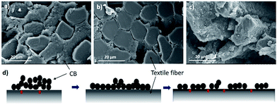
The effect of tensile strain on the conductivity37,38 of the PU@CB@FAB was studied by measuring the resistance with increasing displacement of its original length. According to the Fig. 3b, upon 5% displacement, the resistance decreases by around 10 Ω cm−1 and then it retains its conductivity up to 25%. Upon further increasing the displacement, the resistance also starts increasing. In order to explain a possible mechanism for the relationship between the percent displacement and conductivity, Scanning Electron Microscopy (SEM) for imaging their morphologies under 0%, 10%, and 50% strain (Fig. 3) was done.
In Fig. 4 the SEM cross sectional analysis shows, when there is no strain across the fabric, a thick layer of CB is found in between the polyester fibers. Although there is a large amount of CB present, the contact between the CB particles and the polyester fiber is not very efficient (Fig. 4a) due to the fewer contact points between the CBs and textile fibers. The moderately high conductivity at 0% strain is due to the high amount of CB present per unit length.
However, when the displacement is 10%, the thickness of CB filling between fabric fibers decreases and CB particles get conformally adhered to the surface of polyester fibers which maximize the contact area between the textile fibers and the CB filling (Fig. 4b).39 This excellent mechanical adhesion of CBs on fabric surface decreases the path length for electrons to travel, hence increases the conductivity. In contrast to the other studies where the conductivity decreases with stretching,40,41 in the present study, the conductivity increases and remains stable till the displacement of 25%. At 5% displacement it reaches its maximum number of contact points and further stretching up to 25% will not affect the degree of surface contact between the CB and textile fibers. As Fig. 4c shows, when strain increases further, the conductivity starts decreasing due to inhomogeneous deformations, reduced cross sectional area and the discontinuity of the conductive path (Fig. 4d). The universality of the conductive system on different fabric types, polyester (PU@CB@POL), cotton (PU@CB@COT), polyester–spandex (PU@CB@POL–SPAN) and nylon (PU@CB@NYL) was tested (Fig. S9†) and they showed resistance values of 71, 94, 136 and 164 Ω cm−1, respectively. Hence, the conductive coating and the application method could be considered as a viable option for the production of conductive fabrics from different fabric types.
3.3 Conductive fabrics for heating applications
The heating performances of the CB treated fabric was studied through measuring the change in temperature at the surface of the fabric while applying a voltage difference across the fabric (Fig. 5a). The maximum temperature observed was for PU@CB@CB@FAB since, the amount of heat generated is related to I2 as given in eqn (1).| P = I2R | (1) |
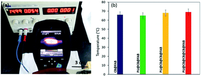 | ||
| Fig. 5 (a) Measurement of surface temperature using IR camera and (b) surface temperatures of conductive fabric prepared in different ways. | ||
In order to study the stability of the surface heating of CB treated conductive fabric, the temperature was measured as a function of time with an applied voltage of 15 V (Fig. 7). The constructed 4 cm × 3 cm piece of fabric clearly demonstrated the stability of heat generated under voltage difference. The temperature on the fabric surface increased up to 62 °C within 1 min and then it slowly increased up to 65 °C within 30 min. Moreover, the experiment was carried out up to 60 min and the measured surface temperature was stable throughout the duration of the experiment with a homogenous temperature distribution. In a similar study where they have functionalized cotton fabric with carbon nanotubes (CNT), it completely loses the heating power of the conductive fabric after 220 s. On the other hand, in the present study the stability of the conductive fabric constructed with much more economically favourable CB is retained even after 60 min. The stability and the reliability of the CB treated fabric heaters was tested via a heat cycle test as a function of time. The on/off ratio of the heat cycle was set to 100 s. The faster heating cooling response and the maximum steady state temperature together demonstrates the very high stability and reusability of the constructed material as a fabric heater showing a high performance. Moreover, the surface temperature does not reduce significantly when the PU@CB@FAB is subjected to zero, one, and two bending cycles (65.0, 61.4, and 58.5 °C, respectively). The conductive paths in PU@CB@FAB remain intact without breaking and this reflects the strong binding of CB to the fabric (Fig. S10†).
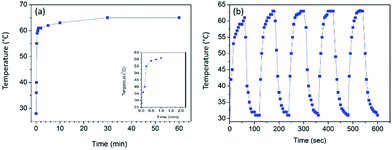 | ||
| Fig. 7 (a) Heating experiment of PU@CB@FAB as a function of time (b) temperature response of PU@CB@FAB under a heat cycle. | ||
4. Conclusions
In the present study, carbon black based stretchable and conductive textile fabric was designed, formulated, and constructed. The constructed carbon black treated fabric was characterized and its applicability as a wearable heater was tested. The fabricated material showed a resistance value of 71 Ω cm−1 while the maximum temperature reached was 65 °C. Moreover, it can be concluded that the present method can be applied to different fabric types. The electro thermal response was verified with respect to response time and the input voltage. The polyurethane/carbon black/polyester fabric system constructed in the present study showed a very high stability, repeatability and a quick response. Moreover, the present system showed excellent flexibility and stretchability due to the properties of polyurethane matrix. The obtained results demonstrates that PU@CB@FAB system is a promising candidate for low cost wearable, flexible, and stretchable heaters. This system can further be developed for heating applications by using different additives such as IR reflectors. Also the constructed system can be developed as supercapacitors for applications in wearable electronics.References
- A. A. Balandin, S. Ghosh, W. Bao, I. Calizo, D. Teweldebrhan, F. Miao and C. N. Lau, Nano Lett., 2008, 8, 902–907 CrossRef CAS PubMed.
- D. Yu, H. Liu, L.-M. Peng and S. Wang, ACS Appl. Mater. Interfaces, 2015, 7, 3462–3467 CAS.
- L. Xue, G. Xu, Y. Li, S. Li, K. Fu, Q. Shi and X. Zhang, ACS Appl. Mater. Interfaces, 2013, 5, 21–25 CAS.
- J. T. Han, B. G. Kim, M. Yang, J. S. Kim, H. J. Jeong, S. Y. Jeong, S.-H. Hong and G.-W. Lee, ACS Appl. Mater. Interfaces, 2011, 3, 2671–2676 CAS.
- B. Marinho, M. Ghislandi, E. Tkalya, C. E. Koning and G. de With, Powder Technol., 2012, 221, 351–358 CrossRef CAS.
- A. Celzard, J. F. Marêché, F. Payot and G. Furdin, Carbon, 2002, 40, 2801–2815 CrossRef CAS.
- J. Kim, J. Lee, D. Son, M. K. Choi and D.-H. Kim, Nano Convergence, 2016, 3, 1–13 CrossRef PubMed.
- W. Zeng, L. Shu, Q. Li, S. Chen, F. Wang and X.-M. Tao, Adv. Mater., 2014, 26, 5310–5336 CrossRef CAS PubMed.
- H. Sun, X. You, X. Deng, X. Chen, Z. Yang, J. Ren and H. Peng, Adv. Mater., 2014, 26, 2868–2873 CrossRef CAS PubMed.
- M. Shateri-Khalilabad and M. E. Yazdanshenas, Carbohydr. Polym., 2013, 96, 190–195 CrossRef CAS PubMed.
- N. D. Tissera, R. N. Wijesena, J. R. Perera, K. M. N. de Silva and G. A. J. Amaratunge, Appl. Surf. Sci., 2015, 324, 455–463 CrossRef CAS.
- F. Yaghoubidoust, D. H. B. Wicaksono, S. Chandren and H. Nur, J. Mol. Struct., 2014, 1075, 486–493 CrossRef CAS.
- S. Jung, J. Lee, T. Hyeon, M. Lee and D.-H. Kim, Adv. Mater., 2014, 26, 6329–6334 CrossRef CAS PubMed.
- C. Wang, D. Hwang, Z. Yu, K. Takei, J. Park, T. Chen, B. Ma and A. Avey, Nat. Mater., 2013, 12, 899–904 CrossRef CAS PubMed.
- S. Patel, H. Park, P. Bonato, L. Chan and M. A. Rodgers, Journal of NeuroEngineering and Rehabilitation, 2012, 9, 1–17 CrossRef PubMed.
- E. Roh, B.-U. Hwang, D. Kim, B.-Y. Kim and N.-E. Lee, ACS Nano, 2015, 9, 6252–6261 CrossRef CAS PubMed.
- D. Zhang, M. Miao, H. Niu and Z. Wei, ACS Nano, 2014, 8, 4571–4579 CrossRef CAS PubMed.
- J. Liang, L. Li, X. Niu, Z. Yu and Q. Pei, Nat. Photonics, 2013, 7, 817–824 CrossRef CAS.
- Z. Yu, X. Niu, Z. Liu and Q. Pei, Adv. Mater., 2011, 23, 3989–3994 CrossRef CAS PubMed.
- D. Son, J. H. Koo, J.-K. Song, J. Kim, M. Lee, H. J. Shim, M. Park, M. Lee, J. H. Kim and D.-H. Kim, ACS Nano, 2015, 9, 5585–5593 CrossRef CAS PubMed.
- L. Hu, M. Pasta, F. L. Mantia, L. Cui, S. Jeong, H. D. Deshazer, J. W. Choi, S. M. Han and Y. Cui, Nano Lett., 2010, 10, 708–714 CrossRef CAS PubMed.
- S. M. Kim, E. B. Song, S. Lee, J. Zhu, D. H. Seo, M. Mecklenburg, S. Seo and K. L. Wang, ACS Nano, 2012, 6, 7879–7884 CrossRef CAS PubMed.
- S. Pan, H. Lin, J. Deng, P. Chen, X. Chen, Z. Yang and H. Peng, Adv. Energy Mater., 2015, 5, 1401438–1401442 CrossRef.
- H.-K. Ma, P.-C. Chien, M.-C. Tsai, H.-Y. Miao, J.-H. Liu and C.-Y. Huang, Opt. Mater. Express, 2014, 4, 719–724 CrossRef.
- R. H. Baughman, A. A. Zakhidov and W. A. de Heer, Science, 2002, 297, 787–792 CrossRef CAS PubMed.
- P. Ilanchezhiyan, A. S. Zakirov, G. M. Kumar, S. U. Yuldashev, H. D. Cho, T. W. Kang and A. T. Mamadalimov, RSC Adv., 2015, 5, 10697–10702 RSC.
- B. H. Kim, B. S. Barnhart and J. W. Kwon, Micro and Nano Systems Letters, 2015, 3, 1–7 CrossRef.
- K. Jost, C. R. Perez, J. K. McDonough, V. Presser, M. Heon, G. Dion and Y. Gogotsi, Energy Environ. Sci., 2011, 4, 5060–5067 CAS.
- D. Kongahage, J. Forougni, G. M. Spinks and G. G. Wallace, RSC Adv., 2016, 6, 73203–73209 RSC.
- O. Matarredona, H. Rhoads, Z. Li, J. H. Harwell, L. Balzano and D. E. Resasco, J. Phys. Chem. B, 2003, 107(48), 13357–13367 CrossRef CAS.
- H. Sis and M. Birinci, Colloids Surf., A, 2009, 341(1–3), 60–67 CrossRef CAS.
- S. Patil, A. Sandberg, E. Heckert, W. Self and S. Seal, Biomaterials, 2007, 28, 4600–4607 CrossRef CAS PubMed.
- S. D. Gupta and S. S. Bhagwat, J. Dispersion Sci. Technol., 2005, 26(1), 111–120 CrossRef CAS.
- R. M. Silverstein, F. X. Webster, D. J. Kiemle and D. L. Bryce, Spectrometric Identification of Organic Compounds, 8th edn, 2014 Search PubMed.
- S. Natarajan and J. J. Moses, Indian J. Fibre Text. Res., 2012, 287–291 Search PubMed.
- G. Ao, Q. Hu and M. Kim, Carbon letters, 2008, 9, 115–120 CrossRef.
- L. Hu, M. Pasta, F. La Mantia, L. Cui, S. Jeong, H. D. Deshazer, J. W. Choi, S. M. Han and Y. Cui, Nano Lett., 2010, 10, 708–714 CrossRef CAS PubMed.
- Y. Yoon, K. Samant, H. Lee, K. Lee, A. P. Tiwari, J. Lee, J. Yang and H. Lee, Sci. Rep., 2015, 5, 14177 CrossRef CAS PubMed.
- S. Iijima, C. Brabec, A. Maiti and J. Bernholc, J. Chem. Phys., 1996, 104, 2089–2092 CrossRef CAS.
- D. H. Kim and J. A. Rogers, Adv. Mater., 2008, 20, 4887–4892 CrossRef CAS.
- C. M. Yu, J. Rong, B. Wei and H. Jiang, Adv. Mater., 2009, 21(18), 4793–4797 CrossRef CAS PubMed.
- P. Ilanchezhiyan, A. S Zakirov, G. M. Kumar, S. U. Yuldashev, H. D. Cho, T. W. Kang and A. T. Mamadalimov, RSC Adv., 2015, 5, 10697–10702 RSC.
- D. Janas and K. K. A. Koziol, Nanoscale, 2014, 6, 3037–3045 RSC.
- J. W. Jiang and J. S. Wang, J. Appl. Phys., 2011, 110, 124319 CrossRef.
- C. Rutherglen and P. Burke, Small, 2009, 5, 884–906 CrossRef CAS PubMed.
Footnote |
| † Electronic supplementary information (ESI) available. See DOI: 10.1039/c7ra02184d |
| This journal is © The Royal Society of Chemistry 2017 |

