 Open Access Article
Growth of two-dimensional silicalite-1 on graphene oxide with controllable electrical conductivity†
He Ding‡
ab,
Yixiao Zhang‡ab,
Xiuxiu Niab,
Jingshuang Zhangab,
Zhouliangzi Zengab,
Peng Baiab and
Xianghai Guo *ab
*ab
aDepartment of Pharmaceutical Engineering, School of Chemical Engineering and Technology, Tianjin University, Tianjin 300350, China
bKey Laboratory of Systems Bioengineering, Ministry of Education, Tianjin University, Tianjin 300350, China
First published on 21st March 2017
Abstract
Multi-quaternary ammonium surfactants are assembled co-operatively with graphene oxide (GO) to generate two-dimensional (2D) silicalite-1. The hybrid composites behave with controllable electrical conductivity and exhibit a specific surface area (SBET) as high as 643 m2 g−1.
Zeolite nanosheet, a two-dimensional (2D) structure with a thickness corresponding to its single unit cell, has attracted considerable attention in catalysis,1–4 membrane separations,5 low dielectric constant materials,6 and anti-corrosion coatings.7 Research on 2D zeolites synthesis and post-treatment has achieved important developments towards a potential toolbox for non-traditional applications, such as energy storage, and electronic and optical materials.8 Multilamellar and unilamellar MFI with well-defined microporous and mesoporous structures have been synthesized by Ryoo and co-workers,9 in which a multi-quaternary ammonium surfactant (C22-6-6) was used as an innovative organic structure-directing agent (SDA) for generating a multilayer structure. Due to its self-pillared structure, multilamellar MFI zeolite could be directly exfoliated to afford MFI nanosheets, which can uniformly and precisely control the diffusion length at the single-unit-cell scale and then become an advanced material for the fabrication of zeolite membranes10,11 with nano thickness.
Recently, graphene and its derivatives such as graphene oxide (GO) and reduced graphene oxide (rGO), a monolayer of carbon atoms arranged in a 2D honeycomb lattice,12–14 have emerged as promising materials for nanoscale composites. Interestingly, GO with its excellent surface properties, high surface area and good thermal and mechanical stability has been considered as a versatile building block for hybrid nanocomposites or graphene-based soft materials.15–20 ZnO/GO,21 MOFs/GO,22 organic polymer/GO23 and mesoporous silica/GO, which enable the integration of the particular properties of two different materials, have been studied a lot. In addition, by introducing GO into a silicalite system, Wang et al. prepared silicalite-1/GO composites in which large spherical silicalite crystals with mesopores of sizes 20–25 Å were obtained after combustion of the template and GO. Characterizations showed that the GO nanosheets were well intergrown with the silicalite crystals and did enhance the zeolite crystallization.
In this paper, a silicalite-1/GO nanosheet composite was firstly fabricated by introducing GO nanosheets into a multilamellar MFI synthetic system. The compatible intergrowth of these two fascinating nanosheets was confirmed. Differing from the aforementioned silicalite-GO system in which tetrapropylammonium hydroxide (TPAOH) served as a surfactant, in our case, multi-quaternary ammonium (C22-6-6) was used as the template. We envision that the tail of C22-6-6 acts cooperatively with GO. Where the surfactant serves as a lamellar structure-directing agent and GO acts as a two-dimensional facilitating building block, 2D silicalite-1 zeolites were grown along both surfaces of GO. In this way, hierarchical-pore silicalite-1 crystals with a higher specific surface area were created after removal of the surfactant and GO. Meanwhile, the electrical conductivities of silicalite-1/rGO (GO deoxygenated to rGO after calcination at 700 °C under nitrogen atmosphere) were controllable and improved.
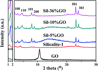
X-ray diffraction (XRD) patterns of silicalite-1, silicalite-1/GO (abbreviated as Sil–GO) composites and dried GO are shown in Fig. 1. Under the same synthetic conditions, silicalite-1 without GO exhibited partially amorphous silica, resulting in a weakening intensity of special peaks. With an increasing amount of GO nanosheets, Sil–GO composites exhibited an enhanced multilamellar structure with better crystallinity,24 indicating that GO improves the crystallization process of the layered zeolite. Our results are in accordance with Wang's argument,25 that GO did significantly induce and enhance the crystallization process of silicalite-1 crystals. Three peaks were observed in the small-angle scattering regime (2θ < 5°). In sample Sil–10% GO, the three Bragg diffractions at 2θ = 1.53° (d = 5.7 nm), 3.09° (d = 2.8 nm) and 4.66° (d = 1.9 nm), demonstrate that the product was layer-structured with an interlayer spacing of 5.7 nm. These special peaks ranging from 1 to 5° were similar to the special peaks in mesoporous zeolite where the greater the number of special peaks appearing in this range, the more the order of a multilayer structure was demonstrated. In pure silicalite-1, there was no 100 peak and the relative intensity of 010 was weaker. With the addition of GO, the 100 peak appeared and the relative intensities of the 010, 100, 110 peaks strengthened. It was clear that GO did enhance the order of the 2D multilayer structure. The diffractions in the wide-angle were in the range of 2θ = 5–30° which could be assigned to the MFI zeolite structure. In conventional silicalite-1, the peaks at 2θ = 7.95° (101), 8.89° (200), 23.18° (501), 23.32° (051), 23.99° (303), 24.45° (133) were assigned as the special peaks. The long-chain of C22-6-6 changed the morphology of silicalite-1 where the peaks (101, 200, 505 and 303) relating to the b-orientation were preserved and enhanced, whereas some other peaks (051 and 133) disappeared. The increased relative intensities of the special peaks demonstrated that GO did enhance the silicalite-1 crystallization process. For the dried GO sample, the only peak at 2θ = 10.70° indicated close stacking of GO nanosheets, where the interlayer distance (d spacing) was calculated to be 8.8 Å, in accordance with a previously reported value of 9.5![[thin space (1/6-em)]](https://www.rsc.org/images/entities/char_2009.gif) Å.23 From the XRD results, no noticeable peak of GO was observed on Sil–GO composites which could be attributed to the low amounts of GO in the samples as well as to unstacked monolayer GO. The lack of long-range order should not give rise to a diffraction peak. This could be evidence for GO being highly dispersed in the composite.26,27
Å.23 From the XRD results, no noticeable peak of GO was observed on Sil–GO composites which could be attributed to the low amounts of GO in the samples as well as to unstacked monolayer GO. The lack of long-range order should not give rise to a diffraction peak. This could be evidence for GO being highly dispersed in the composite.26,27
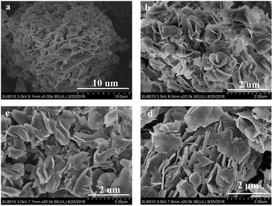
The SEM images in Fig. 2 demonstrate that under the hydrothermal synthesis conditions (150 °C/8 d), silicalite-1 crystals grown in the presence of 5%, 10% or 36% GO exhibited looser and larger lateral plates. These multilayer MFI nanosheets were stacked with reduced intergrowth, compared with Ryoo's compact sphere structures with complicated three-dimensional intergrowth (Fig. S1†), and were expected to be easier to exfoliate to obtain bigger nanosheets for the fabrication of ultrathin zeolite functional membranes.28 All Sil–GO composite samples showed layered stacking of super-thin nanosheets without amorphous silica (Fig. S2†). The as-synthesized samples in our research were around 10 μm spherical aggregations of pure silicalite-1. Sil–5% GO exhibited denser petal-like aggregates, and the petal was stretched to a bigger plate of around 2 μm in length. With the increasing amount of GO, the silicalite-1 in the Sil–10% GO composites exhibited a loose single plate structure of approximately 1–2 μm in length and 50 nm in thickness (Fig. S3†). The aspect ratio of Sil–10% GO silicalite-1 was improved obviously. From the above results, we suggested that the GO nanosheet, serving as a thermally and mechanically stable 2D building block, effectively induced the silicalite-1 crystallization process (no amorphous silica was observed in Fig. 2b–d). Moreover, the addition of GO to the synthetic system considerably suppressed the intergrowth and altered the entire morphology of the silicalite-1 zeolite. By this layer by layer self-assembly, long-standing problems29 such as the relatively small and nonuniform aspect ratio of the nanosheets, and the loss of order and porosity during exfoliation for certain structures, core challenges associated with the production of ultra-thin membranes by exfoliation, would be at least partially solved.
 | ||
| Fig. 2 SEM images of (a) Sil–0% GO (silicalite-1) and (b–d) silicalite-1/GO composites: (b) Sil–5% GO, (c) Sil–10% GO, (d) Sil–36% GO. | ||
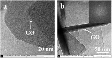
Evidence for the accompanying growth of MFI nanosheets on a GO nanosheet was shown by high-resolution TEM (Fig. 3). As shown in Fig. 3, we suggested that the hydrophilic groups (hydroxyl, oxo group and so on) on GO favourably induced the oriented arrangement of organic structure-directing agents (C22-6-6) through dipole–charge interaction under an alkaline environment, facilitating the nucleation and growth of two-dimensional zeolite. And then the growth of silicalite-1 in the presence of GO occurred through the attachment of amorphous silica onto both sides of the GO surface with repressed Ostwald ripening, gradually producing GO nanosheets wrapped in silicalite-1. Furthermore, the polar groups of GO exerted favourable surface properties so that the nucleation and growth of zeolite crystals were accelerated, resulting in a stretched lateral structure. The inset image in Fig. 2b is the fast Fourier transform of the multilayer structure of silicalite-1, which suggests that the MFI crystal structure was preserved. The dot pattern was identical to the selected area electron diffraction (SAED) pattern of exfoliated b-oriented MFI nanosheets,28 suggesting that the b-oriented nanosheets were directly synthesized under the orientation induced by both SDA and GO nanosheets.
Before the measurement of nitrogen adsorption and desorption isotherms, the as-synthesized Sil–GO composites were calcined at 550 °C for 6 h under air flow. Different from the as-synthesized Sil–GO composites which were grey in colour, the calcined Sil–GO composites appeared to be white in colour, suggesting that SDA and GO had been removed completely.
The calcined Sil–10% GO (SEM in Fig. S4†) exhibited a specific surface area (SBET) of 532 m2 g−1. With an increasing amount of GO, the specific surface area (SBET) of Sil–36% GO had a remarkable augmentation to 643 m2 g−1, compared with that of multilamellar silicalite-1 of 520 m2 g−1 prepared by Ryoo's group9 and that of conventional silicalite-1/GO composites of 359 m2 g−1 prepared by Wang's group.25 We attributed this tendency to the increasing amount of GO nanosheets, where mesopores were generated after the removal of GO (Fig. S5†). Interestingly, it can be deduced from the isotherm curve that the creation of slit-like pores due to the in situ combustion of GO indicated that silicalite-1 nanoparticles grew on both sides of the GO nanosheet to generate sandwich-like silicalite-1/GO/silicalite-1 nanosheet structures. The augmentation in SBET with the increasing amount of GO also demonstrated that more GO served as a platform for the growth of silicalite-1 crystals, and then enhanced 2D induced effects were observed for arrayed silicalite-1 crystals.30
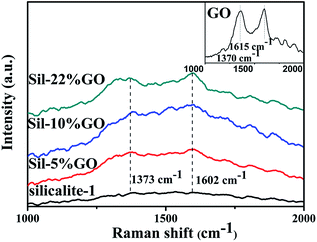
The electrical conductivities of Sil–10% GO and Sil–36% GO composites were measured at room temperature after calcination at 700 °C for 2 h under nitrogen flow, in which GO nanosheets were deoxygenated to rGO during the thermal process.31,32 The as-synthesized Sil–GO composites showed a conductivity of 0.19 S m−1, whereas Sil–rGO after calcination exhibited a remarkably improved electrical conductivity of 208 S m−1 and 423 S m−1 for Sil–10% GO and Sil–36% GO, respectively, suggesting that GO had been transformed into rGO in the composites and that the electrical conductivity was related to the amount of GO nanosheets in the composite. The good proportional relationship between the electrical conductivity of the nanocomposites and the amount of GO offers great opportunity for the manufacture of electrical devices with a continuously adjustable electrical conductivity. Raman spectra of the materials studied are presented in Fig. 4. GO exhibited two broad peaks at 1615 and 1370 cm−1, which were G and D bands, respectively.33,34 These features are consistent with the characteristics of graphene oxide and compared with silcalite-1, the G and D peaks did exist in the composites, displaying the coexistence of GO and the silicalite-1 unit in the hybrid composite.
 | ||
| Fig. 4 Raman spectra of silicalite-1, Sil–5% GO, Sil–10% GO and Sil–36% GO. The inset graph is the Raman spectrum of GO. | ||
Conclusions
In summary, we have developed a method for the preparation of silicalite-1/GO nanocomposites. Hybrid nanosheet composites with improved electrical conductivity (thermally reduced GO) and larger specific surface area (SBET = 643 m2 g−1) are obtained. These materials also exhibit reduced intergrowth in zeolite nanosheets with b-orientation. In principle, this effective strategy has great potential for development as a platform technique for the preparation of a variety of zeolite/GO nanosheet composites and would bring new opportunities for the synthesis of growth-controllable two-dimensional materials for advanced applications, such as gas separation, catalysts and electrochemistry.Acknowledgements
We gratefully acknowledge the funding for this work provided by the National Natural Science Foundation of China (No. 21202116), Independent Innovation Foundation of Tianjin University of China (No. 2016XZC-0071), and Natural Science Foundation of Tianjin of China (No. 16JCYBJC20300).Notes and references
- A. Corma, V. Fornes, S. B. Pergher, T. L. M. Maesen and J. G. Buglass, Nature, 1998, 396, 353–356 CrossRef CAS
.
- B. Marler and H. Gies, Eur. J. Mineral., 2012, 24, 405–428 CrossRef CAS
.
- W.-g. Kim and S. Nair, Chem. Eng. Sci., 2013, 104, 908–924 CrossRef CAS
.
- H.-K. Jeong, S. Nair, T. Vogt, L. C. Dickinson and M. Tsapatsis, Nat. Mater., 2002, 2, 53–58 CrossRef PubMed
.
- C. M. Lew, R. Cai and Y. Yan, Acc. Chem. Res., 2010, 43, 210–219 CrossRef CAS PubMed
.
- L. Tosheva and V. P. Valtchev, Chem. Mater., 2005, 17, 2494–2513 CrossRef CAS
.
- G. J. Myatt, P. M. Budd, C. Price, F. Hollway and S. W. Carr, Zeolites, 1994, 14, 190–197 CrossRef
.
- M. Tsapatsis, AIChE J., 2002, 48, 654–660 CrossRef CAS
.
- M. Choi, K. Na, J. Kim, Y. Sakamoto, O. Terasaki and R. Ryoo, Nature, 2009, 461, 246–249 CrossRef CAS PubMed
.
- K. Varoon, X. Zhang, B. Elyassi, D. D. Brewer, M. Gettel, S. Kumar, J. A. Lee, S. Maheshwari, A. Mittal, C.-Y. Sung, M. Cococcioni, L. F. Francis, A. V. McCormick, K. A. Mkhoyan and M. Tsapatsis, Science, 2011, 334, 72–75 CrossRef CAS PubMed
.
- K. V. Agrawal, B. Topuz, Z. Jiang, K. Nguenkam, B. Elyassi, L. F. Francis, M. Tsapatsis and M. Navarro, AIChE J., 2013, 59, 3458–3467 CrossRef CAS
.
- A. K. Geim and K. S. Novoselov, Nat. Mater., 2007, 6, 183–191 CrossRef CAS PubMed
.
- M. J. Allen, V. C. Tung and R. B. Kaner, Chem. Rev., 2010, 110, 132–145 CrossRef CAS PubMed
.
- J. C. Meyer, A. K. Geim, M. I. Katsnelson, K. S. Novoselov, T. J. Booth and S. Roth, Nature, 2007, 446, 60–63 CrossRef CAS PubMed
.
- H. Song, L. Zhang, C. He, Y. Qu, Y. Tian and Y. Lv, J. Mater. Chem., 2011, 21, 5972 RSC
.
- C. N. R. Rao, A. K. Sood, K. S. Subrahmanyam and A. Govindaraj, Angew. Chem., Int. Ed., 2009, 48, 7752–7777 CrossRef CAS PubMed
.
- D. Chen, H. Feng and J. Li, Chem. Rev., 2012, 112, 6027–6053 CrossRef CAS PubMed
.
- K. Yang, L. Feng, X. Shi and Z. Liu, Chem. Soc. Rev., 2013, 42, 530–547 RSC
.
- X. Li, W. Qi, D. Mei, M. L. Sushko, I. Aksay and J. Liu, Adv. Mater., 2012, 24, 5136–5141 CrossRef CAS PubMed
.
- J. Kim, L. J. Cote and J. Huang, Acc. Chem. Res., 2012, 45, 1356–1364 CrossRef CAS PubMed
.
- X. Chen, Y. He, Q. Zhang, L. Li, D. Hu and T. Yin, J. Mater. Sci., 2009, 45, 953–960 CrossRef
.
- C. Petit and T. J. Bandosz, Adv. Mater., 2009, 21, 4753–4757 CrossRef CAS
.
- L. Hua, W. Kai, Z. Liang and Y. Inoue, J. Polym. Sci., Part B: Polym. Phys., 2010, 48, 294–301 CrossRef CAS
.
- W. Park, D. Yu, K. Na, K. E. Jelfs, B. Slater, Y. Sakamoto and R. Ryoo, Chem. Mater., 2011, 23, 5131–5137 CrossRef CAS
.
- D. Li, L. Qiu, K. Wang, Y. Zeng, D. Li, T. Williams, Y. Huang, M. Tsapatsis and H. Wang, Chem. Commun., 2012, 48, 2249 RSC
.
- S. Park and R. S. Ruoff, Nat. Nanotechnol., 2010, 5, 309 CrossRef CAS
.
- C. Petit and T. J. Bandosz, Adv. Funct. Mater., 2011, 21, 2108–2117 CrossRef CAS
.
- H. Zhang, Q. Xiao, X. Guo, N. Li, P. Kumar, N. Rangnekar, M. Y. Jeon, S. Al-Thabaiti, K. Narasimharao, S. N. Basahel, B. Topuz, F. J. Onorato, C. W. Macosko, K. A. Mkhoyan and M. Tsapatsis, Angew. Chem., Int. Ed., 2016, 55, 7184–7187 CrossRef CAS PubMed
.
- M. Tsapatsis, AIChE J., 2014, 60, 2374–2381 CrossRef CAS
.
- J. Wei, Y. Hu, Z. Wu, Y. Liang, S. Leong, B. Kong, X. Zhang, D. Zhao, G. P. Simon and H. Wang, J. Mater. Chem. A, 2015, 3, 16867–16873 CAS
.
- S. Stankovich, D. A. Dikin, R. D. Piner, K. A. Kohlhaas, A. Kleinhammes, Y. Jia, Y. Wu, S. T. Nguyen and R. S. Ruoff, Carbon, 2007, 45, 1558–1565 CrossRef CAS
.
- P. Ding, S. Su, N. Song, S. Tang, Y. Liu and L. Shi, Carbon, 2014, 66, 576–584 CrossRef CAS
.
- F. Tuinstra, J. Chem. Phys., 1970, 53, 1126 CrossRef CAS
.
- K. N. Kudin, B. Ozbas, H. C. Schniepp, R. K. Prud'homme, I. A. Aksay and R. Car, Nano Lett., 2008, 8, 36–41 CrossRef CAS PubMed
.
Footnotes |
| † Electronic supplementary information (ESI) available: Sample synthesis and characterization methods and Fig. S1–S5. See DOI: 10.1039/c7ra00942a |
| ‡ These authors contributed equally to this work. |
| This journal is © The Royal Society of Chemistry 2017 |


