 Open Access Article
Creative Commons Attribution 3.0 Unported Licence
The effects of humidity on the self-discharge properties of Li(Ni1/3Co1/3Mn1/3)O2/graphite and LiCoO2/graphite lithium-ion batteries during storage
Seoungwoo Byun†
ab,
Joonam Parka,
Williams Agyei Appiahab,
Myung-Hyun Ryou *a and
Yong Min Lee*ab
aDepartment of Chemical and Biological Engineering, Hanbat National University, 125 Dongseodaero, Yuseong-gu, Daejeon 305-719, Republic of Korea. E-mail: mhryou@hanbat.ac.kr; yongmin.lee@hanbat.ac.kr; Fax: +82-42-821-1534; Fax: +82-42-821-1692; Tel: +82-42-821-1534 Tel: +82-42-821-1549
bDepartment of Energy Systems Engineering, Daegu Gyeongbuk Institute of Science and Technology (DGIST), 333 Techno Jungang-Daero, Hyeongpung-Myeon, Dalseong-Gun, Daegu 42988, South Korea
First published on 10th February 2017
Abstract
To investigate the effects of the exposure of battery tabs to humidity on the self-discharge properties of full-cell type lithium-ion batteries (LIBs), we assembled two different types of LIBs, composed of NCM/graphite or LCO/graphite, and compared their discharge retention abilities after storage in humid conditions (90% relative humidity (RH)) with and without battery tab protection. Regardless of the type of cathode active materials, tab protection improved the calendar lives of LIBs. For NCM/graphite, battery tab protection shows an approximate 50% improvement in the discharge capacity compared to the case without battery tab protection after storage in humid conditions (51.1% and 34.6% of the initial discharge capacity for tab-protected and non-protected LIBs, respectively). In contrast, LCO/graphite reveals a smaller change in the discharge capacity retention for the same experimental condition because they show superior capacity retention abilities regardless of battery tab protection (85.6% and 82.0% retention of the initial discharge capacity for tab-protected and non-protected LIBs, respectively). We suggested that these results come from the induction effect of polar water molecules, which pulls electrons to the battery tab side, resulting in lithium ion loss from the graphene layers to the liquid electrolyte.
Introduction
Fossil fuel depletion and global warming are considered to be serious problems threating the very existence of the human race. To overcome these threats, the demand for electric vehicles (EVs) and energy storage systems (ESSs) has recently grown rapidly. For several decades, lithium-ion batteries (LIBs) have powered consumer electronics, including cell phones and laptops, due to their high energy densities, high rate capabilities, safety, long calendar life, and long cycle life.1–4 Accordingly, it is obvious that LIBs have been considered as a promising candidate to power large-scale battery applications.In general, development of the major battery components, including cathodes, anodes, separators, and electrolytes, is the first priority to improve the electrochemical performances of LIBs because they directly and/or indirectly participate in electrochemical reactions in the batteries. Frmo a practical point of view for large-scale LIBs, however, it is important to note that not only does the battery configuration play an important role in determining battery performance but also the battery storage environment. Thus far, the latter aspect has been underestimated in consumer electronics as compared to LIBs for large-scale applications. These differences include the following. (1) Large-scale applications such as EVs and ESSs are generally exposed to outdoor environments during most of their lifetime. This implies that large-scale batteries are exposed to uncontrolled outdoor conditions such as high humidity and hot and/or cold temperature conditions in a range between −30 and 52 °C (FreedomCAR operating temperature range goal).5 (2) Large-scale applications are intermittently operated during the day. For instance, according to the results of a survey conducted by the AAA Foundation, American drivers, who make two driving trips per day, drive, on average, only 46 min a day.6 (3) Large-scale LIBs require a higher standard for battery calendar and cycle life, which generally includes a 15 year warranty.7 In conclusion, in contrast to consumer electronics, large-scale LIBs are operated in a standby mode while being exposed to harsh outdoor conditions. Consequently, to guarantee long-term calendar life and cycle performance, the effect of the storage condition on the battery performance of LIBs should be carefully considered.
If charged LIBs are stored for a long time in standby mode, it can be easily observed that their open-circuit voltage (OCV) decreases gradually, and accordingly, the discharge capacity is reduced.7–9 This phenomenon is called self-discharge. Despite the importance of this issue, as discussed above, this phenomenon has not been considered seriously thus far because consumer electronics are designed for daily use. Only a few studies regarding the effect of temperature and state-of-charge (SOC) on LIB self-discharge during storage have been reported. Worse still, the effect of humidity has rarely been reported.7,10–13
In this study, we investigate the effect of humidity on battery performance, in particular the self-discharge characteristics of LIBs, as a function of the storage period, temperature and the type of cathode materials (LiCoO2 (LCO) or Li(Ni1/3Co1/3Mn1/3)O2 (NCM)). LCO has been widely used in commercialized LIBs, and NCM has been considered as an attractive cathode material for large-scale applications due to its advantages such as high energy density, lower toxicity, high safety performance, and lower cost.14,15 Power capabilities, OCV changes, and capacity retention abilities of LIBs based on NCM/graphite were investigated after storage under humid condition (90% relative humidity) for 30 days. Possible aging mechanisms are also suggested and discussed.
Experimental
Preparation of cathodes and anodes
Two types of cathodes were prepared based on Li(Ni1/3Co1/3Mn1/3)O2 (NCM, 10 μm, NCM-070, Ecopro, Korea) and LiCoO2 (LCO, 10 μm, KD-10, Umicore, Korea). NCM and LCO were used as the active materials for NCM and LCO cathodes, respectively. Each electrode was prepared by casting a N-methyl-2-pyrrolidone (NMP, Sigma-Aldrich, USA) based slurry consisting of 90 wt% active material, 5 wt% conductive additives (Super-P, Imerys, Switzerland), and 5 wt% polyvinylidene fluoride (PVdF, KF-1300, Kreha, Japan, Mw = 350![[thin space (1/6-em)]](https://www.rsc.org/images/entities/char_2009.gif) 000) binder onto aluminium foil (15 μm, San-A Aluminium, Korea) using a doctor blade. The cast slurry was dried in an oven at 130 °C for 1 h and then calendered with a gap-control-type roll-pressing machine (CLP-2025, CIS, Korea). The loading level was 10.3 and 11.0 mg cm−2 and the thickness was 35 and 37 μm for the NCM and LCO cathode, respectively. The graphite anode was prepared by casting a NMP-based slurry consisting of 90 wt% graphite (natural graphite, 15 μm, MPG, Mitsubishi, Japan), 5 wt% Super-P, and 5 wt% PVdF binder onto copper foil (10 μm, Iljin Materials, Korea) using a doctor blade. The cast slurry was dried in an oven at 80 °C for 2 h and then calendered with a gap-control-type roll-pressing machine. The loading level and the thickness of the graphite anodes were controlled to be 5.1 mg cm−2 and 34 μm, respectively.
000) binder onto aluminium foil (15 μm, San-A Aluminium, Korea) using a doctor blade. The cast slurry was dried in an oven at 130 °C for 1 h and then calendered with a gap-control-type roll-pressing machine (CLP-2025, CIS, Korea). The loading level was 10.3 and 11.0 mg cm−2 and the thickness was 35 and 37 μm for the NCM and LCO cathode, respectively. The graphite anode was prepared by casting a NMP-based slurry consisting of 90 wt% graphite (natural graphite, 15 μm, MPG, Mitsubishi, Japan), 5 wt% Super-P, and 5 wt% PVdF binder onto copper foil (10 μm, Iljin Materials, Korea) using a doctor blade. The cast slurry was dried in an oven at 80 °C for 2 h and then calendered with a gap-control-type roll-pressing machine. The loading level and the thickness of the graphite anodes were controlled to be 5.1 mg cm−2 and 34 μm, respectively.
Cell preparation
To fabricate full-type unit cells, cathodes, anodes and separators (ND420, Asahikasi, Japan, thickness = 20 μm, porosity = 40%) were cut into 3 cm × 3 cm, 3.2 cm × 3.2 cm and 3.5 cm × 3.5 cm squares, respectively. Separators were sandwiched between cathodes and anodes and the stacked assemblies were inserted into aluminium-laminated film (DNP 145, DNP, Japan). Three sides of the laminated film were sealed at 200 °C under 4 MPa using a hot sealer. Electrolyte (400 μL, a mixture of 1.15 M LiPF6 containing ethylene carbonate/ethyl methyl carbonate = 3/7 by v/v, Enchem, Korea, battery grade with water content <3 ppm) were injected and the final side of the aluminium laminated film was sealed using a vacuum-hot sealer. Unit cell assembly procedures were conducted in an argon-filled glove box.Electrochemical measurement
After unit cell assembly, the NCM and LCO full cells were aged for 12 h and cycled at C/10 (0.133 for NCM and 0.125 mA cm−2 for LCO, respectively) at a constant current (CC) mode for charging and a CC mode for discharging in a voltage range between 3.0 and 4.2 V. To stabilize the unit cells, both types of cells were charged at C/5 at a constant current/constant voltage (CC/CV) mode for charging and at a CC mode for discharging for a subsequent three cycles in a voltage range between 3.0 and 4.2 V. Battery operation was conducted at 25 °C under 35% relative humidity (RH).A.C. impedance (VSP, Bio Logic SAS, France) measurements were performed in a frequency range between 1 MHz and 0.05 Hz (10 mV amplitude).
Pulse-power capability measurement
Pulse-power capabilities (charge/discharge) of the unit cells were measured using a hybrid pulse power characterization (HPPC) technique. The test consists of a 10 s discharge pulse (5C), 40 s rest, and a 10 s charge pulse (3.75C). The pulse-power capabilities were estimated as follows:16–18| Discharge resistance (Rdischarge) = ΔV/Idischarge = Vt1 − Vt0/Idischarge |
| Pdischarge = 3.0 × (open circuit voltage − 3.0)/Rdischarge |
| Charge resistance (Rcharge) = ΔV/Icharge = Vt3 − Vt2/Icharge |
| Pcharge = 4.2 × (4.2 − open circuit voltage)/Rcharge |
Storage test at humid condition
After unit cell stabilization, the NCM and LCO full cells were fully charged at 4.2 V at 1C in a CC/CV mode. After that, the battery tabs of half of the batteries of each type were sealed using polyimide tape (Kapton® tape) and stored under humid conditions (90% RH) at 25 °C for 30 days in an incubator (TH-ME 025, JSR, Korea). The other half of the batteries were stored at the same condition without any treatment on the battery tabs as controls. The open circuit voltage (OCV) of the stored NCM and LCO unit cells was evaluated during storage every three days.After storage, to evaluate the residual discharge capacity, the NCM and LCO unit cells were discharged at 1C (25 °C at 35% RH) at a CC mode. Again, to stabilize the unit cells, they were operated five times at 1C (a CC/CV mode for charging and a CC mode for discharging) in a voltage range between 3.0 and 4.2 V.
Results and discussion
LIBs have several design formats: prismatic, cylindrical and pouch. Among these, pouch-type LIBs have recently grown in popularity compared to the others because pouch-type LIBs allow greater freedom in designing a battery's shape and dimensions and can help reduce the weight and cost.19,20 Furthermore, they easily release excess heat to the environment. Aluminium (Al) laminated film, which consists of several layers laminated together with an adhesive material, are used to form the pouch cases. To investigate the effect of humid air on LIB performances, we assembled pouch-type LIB full cells consisting of NCM/graphite in a glove box. For half of the cells, both battery tabs, aluminium tabs for the NCM cathodes and nickel tabs for the graphite anodes, were sealed using polyimide tape (Kapton® tape). This treatment was intended to prevent direct contact of the humid air with the battery tab surfaces during storage in a humid condition. Throughout this study, for convenience, we denoted the LIBs with Kapton® tape-protected tabs without tab protection as tab-treated LIBs and non-treated LIBs, respectively. Both the tab-treated LIBs and non-treated LIBs were electrochemically operated at exactly the same condition.The Al-laminated film is considered to be a moisture barrier, a vapor barrier, and resistant to the electrolyte. To prove this, we stored NCM/graphite pouch-type LIBs under humid conditions (90% RH for 30 days) and water content in electrolyte was determined by coulombic Karl-Fischer titration (Karl-Fischer coulometer, Metrohm 756KF, USA) As shown in Fig. 1, the electrolyte after storage showed almost the same level of moisture as the control electrolytes (moisture concentration in the electrolyte before storage = 3.4 ppm, moisture concentration in the electrolyte after storage = 3.7 ppm). This implies that the Al-laminated film functions well as a moisture battier during storage. Considering this result, it can be inferred that the monitored electrochemical performance changes of the LIBs stored under humid conditions, which will be discussed below, is not directly related to the moisture penetration in the LIBs.
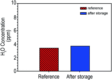 | ||
| Fig. 1 Comparison of water contents in pouch-type LIBs (NCM/graphite) before (reference) and after storage at 25 °C at 90RH for 30 days. | ||
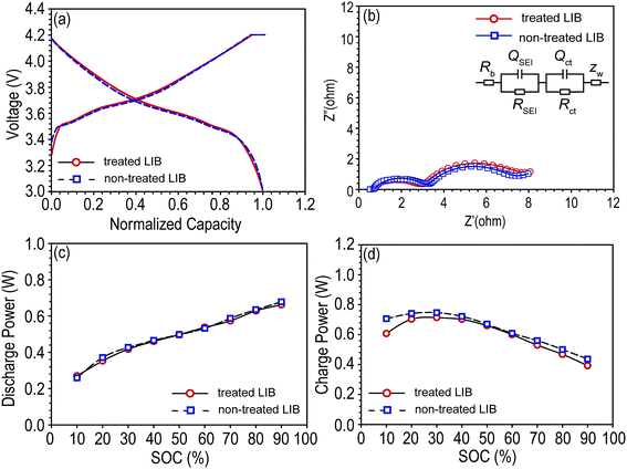
Pouch-type NCM/graphite LIBs were pre-cycled, and the A.C. resistance were monitored (Fig. 2b), and fitted resistance values are shown Table 1. The Rb is the bulk resistance of the cell; RSEI and QSEI are resistance and constant phase element (CPE) of the solid–state interface layer formed on the surface of the electrodes; Rct and Qct are charge-transfer resistance and its relative CPE; ZW is Warburg impedance related to a combination of the diffusional effects of lithium ion on the interface between the active material particles and electrolyte.21–23 CPE has been used instead of capacitance to offset the depression of the semi-circle. The power capabilities (charge power and discharge power) of each cell were monitored (Fig. 2c and d). As shown in Fig. 2 and Table 1, every cell had similar electrochemical properties and interfacial resistances.
| Fitted resistance (ohm) | Rb | RSEI | Rct |
|---|---|---|---|
| Treated LIB | 0.8 | 4.256 | 1.905 |
| Non-treated LIB | 0.7 | 3.907 | 2.522 |
Before storage, tab-treated LIBs were prepared by sealing both battery tabs with Kapton® tape. Fully charged tab-treated LIBs and non-treated LIBs were placed in a humid condition (90% RH) and their OCV was monitored as function of time. As shown in Fig. 3, non-treated LIBs revealed a fast drop in the OCV compared to the tab-treated LIBs (tab-treated LIBs = 4.06 V, non-treated LIBs = 3.98 V after 30 days of storage).
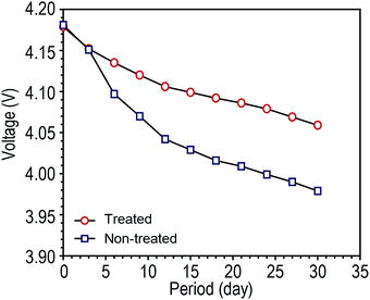 | ||
| Fig. 3 Open circuit voltage (OCV) changes of fully charged LIBs (NCM/graphite) without battery tab protection during storage at humid condition (25 °C at 90 RH) as a function of storage time. | ||
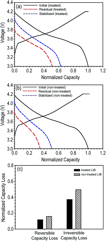
To determine the effect of the decrease in OCV on battery performance, we evaluated the discharge capacity loss for each battery type. First, the stored fully charged LIBs were fully discharged (1C) to measure their residual discharge capacity. As expected from their higher OCV value, tab-treated LIBs demonstrated higher residual discharge capacity than non-treated LIBs (tab-treated LIBs = 6.43 mA h, 51% of initial discharge capacity; non-treated LIBs = 4.23 mA h, 34.6% of initial discharge capacity). Second, the discharged LIBs were charged and discharged at a 1C rate at the same condition used for pre-cycling shown in Fig. 2a. As shown in Fig. 4a and b, during this subsequent cycling, the discharge capacity increased for both the tab-treated LIBs and non-treated LIBs. Tab-treated LIBs and non-treated LIBs achieved 11.7% (from 6.43 to 7.9 mA h) and 15.9% (from 4.23 to 6.16 mA h) discharge capacity enhancements, respectively. Columbic efficiencies were 101.5 (7.87 and 7.90 mA h for charging and discharging processes, respectively) and 99.9% (6.15 and 7.90 mA h for charging and discharging processes, respectively) for tab-treated LIBs and non-treated LIBs, respectively.
As observed in the discharge capacity increase of the LIBs during the subsequent cycling, discharge capacity loss can be divided into two categories: reversible capacity loss and irreversible capacity loss.8,24 The former corresponds to the increased amount of discharge capacity during subsequent cycling. Based on the electron–ion–solvent complex model, intercalated lithium ions in the graphite anodes tend to diffuse to the graphene edges driven by the chemical potential created by adsorbed solvent and anions.8 Electrons are not fully transferred to the solvent and anions but shared between the graphite and the electrolyte through the lithium ions. The electrons participating in forming the electron–ion–solvent complexes are used during the discharging process (de-intercalated from graphite) because the lithium ions of the complex have been di-intercalated and physically dangled at the graphene edge. Consequently, these lithium ions associated with the electron–ion–solvent complex can be reversibly intercalated into graphite during subsequent charging process, and thus, classified as reversible discharge capacity loss. On the other hand, there is no self-discharge mechanism associated with cathode electrode thus far.25
In contrast, lithium ions can easily participate in forming chemical reaction by-products, i.e., solid–electrolyte interphase (SEI), because they are electrochemically active. Lithium-ions, which are chemically and electrochemically reacted with solvent and anion molecules to form SEI, are permanently not able to participate in reversible intercalation and de-intercalation processes. Lithium ions associated in these decomposition reactions are classified as irreversible discharge capacity loss. For convenience, we summarize the reversible and irreversible capacity losses of tab-treated LIBs in Fig. 4c. Regardless of the presence of tab protection, irreversible capacity loss comprises a large portion of the total discharge capacity loss (tab-treated LIBs = 11.72 and 37.2% for reversible and irreversible capacity loss, respectively; non-treated LIBs = 15.9 and 49.5% for reversible and irreversible capacity loss, respectively).
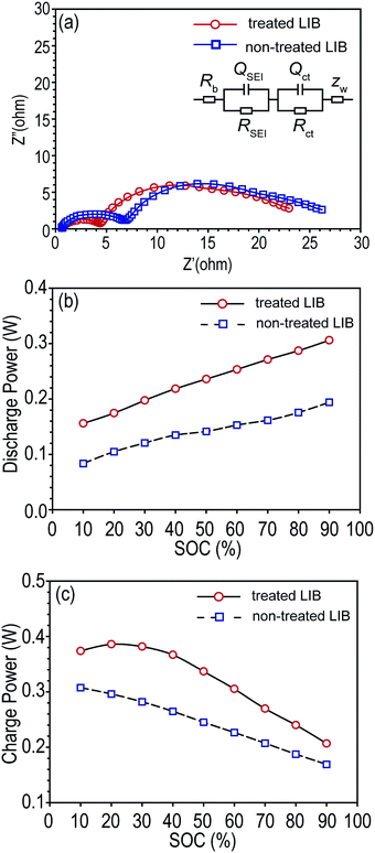
After storage, non-treated LIBs showed larger interfacial resistances than tab-treated LIBs as shown in Fig. 5a. Rb, RSEI, and Rct were summarized in Table 2. Accordingly, the increased interfacial resistances of non-treated LIBs resulted in poor charging and discharging power capabilities compared to tab-treated LIBs, as shown in Fig. 5b and c.
| Fitted resistance (ohm) | Rb | RSEI | Rct |
|---|---|---|---|
| Treated LIB | 0.612 | 15.22 | 3.799 |
| Non-treated LIB | 0.621 | 17.61 | 4.095 |
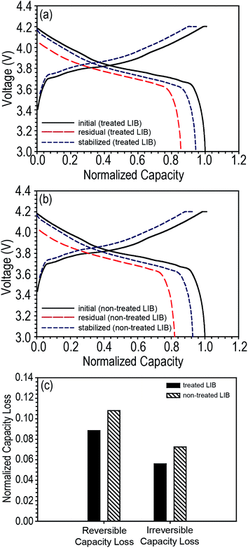
We further investigated the discharge capacity loss of LIBs based on LCO cathodes. Pouch-type LCO/graphite LIBs were assembled and the same storage experiment was conducted that was done on the NCM/graphite LIBs. Surprisingly, regardless of the presence of tab protection, LCO-based LIBs showed a very small discharge capacity loss compared to NCM-based LIBs, and furthermore, the irreversible capacity loss was smaller than the reversible capacity loss (tab-treated LCO-LIBs = 8.84 and 5.59% for reversible and irreversible capacity loss, respectively; non-treated LCO-LIBs = 10.79 and 7.25% for reversible and irreversible capacity loss, respectively) as shown in Fig. 6.
Considering that both LCO/graphite and NCM/graphite LIBs utilize graphite as the anode active material, the inferior discharge capacity retention ability of the NCM/graphite LIBs might be attributed to the NCM active materials. It has been suggested that the metal ions dissolved from the NCM into the electrolyte seem to be a primary reason for the severe performance degradation of NCM-based LIBs.26,27 In general, dissolved metal ions such as Mn(II), Ni(II), and Co(II) have a higher reduction potential compared to that of a Li ion intercalated into graphite, and this makes the Mn(II), Ni(II), and Co(II) ions reduce on the graphite surface prior to the Li ion. Reduced metals provoke chemical and/or electrochemical reactions that consume lithium ions to from SEI.28,29 Considering this explanation, it is reasonable that NCM/graphite LIBs had a higher fraction of irreversible capacity loss than reversible capacity loss.
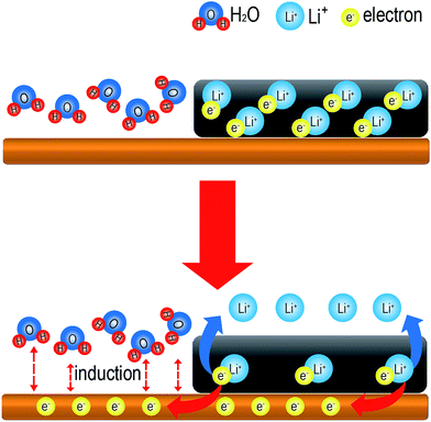
Regardless of the type of cathode active material, we observed that the tab-treated LIBs showed improved discharge capacity retention than non-treated LIBs. What produces the superior performance of the tab-treated LIBs during storage under humid conditions? The answer is the surface protected battery tabs. Exposure of the battery tabs of tab-treated LIBs to water molecules is successfully prohibited, while those of non-treated LIBs are exposed to water molecules. Water is made up of two hydrogen atoms and an oxygen. Therefore, it is easily affected by an electrical charge. As demonstrated in the schematic drawing in Fig. 7a, electrons cling to intercalated lithium ions between the graphene layers at a charged state. As shown in Fig. 7b, if polar water molecules induce electrons to move to the battery tabs, this will cause lithium ion loss form the graphene edges to the electrolyte. Due to the loss of the electron–lithium ion attraction, polar solvent and anions in the electrolyte would drive lithium ions easily into the electrolyte, which would be the origin of reversible capacity loss.
For irreversible capacity loss, electrons and lithium-ions should be consumed permanently in chemical and/or electrochemical reactions. The exact origin of increased irreversible capacity loss cannot be clearly elucidated at present because every SEI formation reaction involves complex combination of electrons and lithium ions.25 Nevertheless, we believe the water molecule induction plays catalytic surface decomposition reactions on the graphite surfaces to form extra SEI as well as the deposited metal ions did on graphite surface.28 Still, we do not believe there would be a significant role of water molecule induction on cathode side because there is no self-discharge mechanism associated with cathode electrode thus far. The mechanism of irreversible capacity loss should be further studied in the near future.
Conclusion
By comparing the self-discharge properties of NCM/graphite and LCO/graphite LIBs, we confirmed that exposure of the battery tab to humid conditions during storage greatly affects the self-discharge properties of LIBs. Regardless of the cathode active materials, battery tab protection efficiently improves the discharge capacity retention abilities of LIBs. Battery tab protection was more effective for NCM/graphite, which suffers from metal ion dissolution during storage, resulting in severe SEI formation on the graphite surfaces. We believe that polar water molecules induce electrons that were used to hold the lithium ion between the graphene layers to move from the graphite to the battery tabs. This promotes lithium ion loss from the graphene layers to the electrolyte and it the origin of both the reversible and irreversible capacity loss.Acknowledgements
This research was supported by Basic Science Research Program through the National Research Foundation of Korea (NRF) funded by the Ministry of Science, ICT & Future Planning (2014R1A1A1005861). This work was also supported by a Commercialization Promotion Agency for R&D Outcomes Grant funded by the Korean Government (MSIP) (2014-2019, 2016K000081, Joint Research Corporations Support Program).Notes and references
- M. H. Ryou, Y. M. Lee, J. K. Park and J. W. Choi, Adv. Mater., 2011, 23, 3066–3070 CrossRef CAS PubMed.
- J.-M. Tarascon and M. Armand, Nature, 2001, 414, 359–367 CrossRef CAS PubMed.
- M. H. Ryou, D. J. Lee, J. N. Lee, Y. M. Lee, J. K. Park and J. W. Choi, Adv. Energy Mater., 2012, 2, 645–650 CrossRef CAS.
- M. Armand and J.-M. Tarascon, Nature, 2008, 451, 652–657 CrossRef CAS PubMed.
- G. Hunt and C. Motloch, Freedom Car Battery Test Manual for Power-Assist Hybrid Electric Vehicles, INEEL, Idaho Falls, 2003 Search PubMed.
- T. Triplett, R. Santos and S. Rosenbloom, American Driving Survey: 2014–2015, AAA Foundation for Traffic Safety, 2016, pp. 9–14 Search PubMed.
- Y. Qin, Z. Chen, W. Lu and K. Amine, J. Power Sources, 2010, 195, 6888–6892 CrossRef CAS.
- R. Yazami and Y. F. Reynier, Electrochim. Acta, 2002, 47, 1217–1223 CrossRef CAS.
- B. E. Conway, W. Pell and T. Liu, J. Power Sources, 1997, 65, 53–59 CrossRef CAS.
- S. Käbitz, J. B. Gerschler, M. Ecker, Y. Yurdagel, B. Emmermacher, D. André, T. Mitsch and D. U. Sauer, J. Power Sources, 2013, 239, 572–583 CrossRef.
- T. Utsunomiya, O. Hatozaki, N. Yoshimoto, M. Egashira and M. Morita, J. Power Sources, 2011, 196, 8598–8603 CrossRef CAS.
- R. P. Ramasamy, R. E. White and B. N. Popov, J. Power Sources, 2005, 141, 298–306 CrossRef CAS.
- I. Bloom, B. Cole, J. Sohn, S. Jones, E. Polzin, V. Battaglia, G. Henriksen, C. Motloch, R. Richardson and T. Unkelhaeuser, J. Power Sources, 2001, 101, 238–247 CrossRef CAS.
- I. Cho, J. Choi, K. Kim, M.-H. Ryou and Y. M. Lee, RSC Adv., 2015, 5, 95073–95078 RSC.
- T. Ohzuku and Y. Makimura, Chem. Lett., 2001, 642–643 CrossRef CAS.
- H. Lee and Y. M. Lee, J. Korean Electrochem. Soc., 2015, 15, 115–123 CrossRef.
- I. Bloom, S. A. Jones, V. S. Battaglia, G. L. Henriksen, J. P. Christophersen, R. B. Wright, C. D. Ho, J. R. Belt and C. G. Motloch, J. Power Sources, 2003, 124, 538–550 CrossRef CAS.
- C. Freedom, Tech. Rep. DOE/ID-11069, US Dept. Energy, Washington, DC, USA, 2003 Search PubMed.
- C. Pillot, Presentation at 31st International Battery Seminar, Fort Lauderdale, 2013 Search PubMed.
- Quarterly Global Small-sized Li-ion Secondary Battery Shipment, in SNE Research, 2015, p. 91 Search PubMed.
- S. Zhang, K. Xu and T. Jow, Electrochim. Acta, 2004, 49, 1057–1061 CrossRef CAS.
- G. Zhao, Y. Lin, T. Zhou, Y. Lin, Y. Huang and Z. Huang, J. Power Sources, 2012, 215, 63–68 CrossRef CAS.
- G. Ning, B. Haran and B. N. Popov, J. Power Sources, 2003, 117, 160–169 CrossRef CAS.
- R. P. Ramasamy, J.-W. Lee and B. N. Popov, J. Power Sources, 2007, 166, 266–272 CrossRef CAS.
- L. Gireaud, S. Grugeon, S. Laruelle, S. Pilard and J.-M. Tarascon, J. Electrochem. Soc., 2005, 152, A850–A857 CrossRef CAS.
- K. S. Kang, S. Choi, J. Song, S.-G. Woo, Y. N. Jo, J. Choi, T. Yim, J.-S. Yu and Y.-J. Kim, J. Power Sources, 2014, 253, 48–54 CrossRef CAS.
- H. Zheng, Q. Sun, G. Liu, X. Song and V. S. Battaglia, J. Power Sources, 2012, 207, 134–140 CrossRef CAS.
- S. Komaba, N. Kumagai and Y. Kataoka, Electrochim. Acta, 2002, 47, 1229–1239 CrossRef CAS.
- M.-H. Ryou, G.-B. Han, Y. M. Lee, J.-N. Lee, D. J. Lee, Y. O. Yoon and J.-K. Park, Electrochim. Acta, 2010, 55, 2073–2077 CrossRef CAS.
Footnote |
| † These authors contributed equally to this work. |
| This journal is © The Royal Society of Chemistry 2017 |

