 Open Access Article
Creative Commons Attribution 3.0 Unported Licence
Dynamics of premixed methane/air mixtures in a heated microchannel with different wall temperature gradients
V. Ratna Kishorea,
S. Minaevb,
M. Akram c and
Sudarshan Kumar
 *d
*d
aDepartment of Mechanical Engineering, Amrita School of Engineering, Amrita Vishwa Vidyapeetham, Amrita University, Coimbatore, India
bFar Eastern Federal University, Vladivostok, Russia
cDepartment of Aeronautical Engineering, King Abdulaziz University, Jeddah, Saudi Arabia
dDepartment of Aerospace Engineering, Indian Institute of Technology Bombay, Powai, Mumbai, India. E-mail: sudar@aero.iitb.ac.in; Fax: +91 22 2572 2602
First published on 12th January 2017
Abstract
The observation of various flame propagation modes for externally heated tubes has led to many fundamental studies aimed at understanding flame propagation in microtubes. During these studies, it has been observed that for moderately low flow velocities, flames with repetitive extinction and ignition (FREI) have been observed to exist in various experimental, theoretical and numerical studies. The formation of these FREI flame modes depends on various parameters such as channel dimensions, wall temperature gradient, flow rates and mixture type. In the present work, an effort has been made to understand the effect of the wall temperature gradient on the FREI phenomenon through a 1 mm diameter circular tube using 2D numerical studies with detailed GRI Mech3.0 for premixed methane/air mixtures. The different wall temperature gradients analyzed are varied from 33.3–1 K mm−1, with an upper range corresponding to experimental conditions. Five different phases of flame propagation have been observed during the FREI flame propagation mode. The entire fuel gets consumed during the cycle and a significant amount of unburned CO remains during the weak reaction phase, towards the extinction of FREI mode. The effect of the wall temperature gradient on the FREI ignition phenomenon has been investigated to understand the development of ignition kernels. It is observed that the ignition happens at the axis and not at the wall of the channel. This happens due to a boundary-layer phenomenon discouraging ignition at the wall. It has been observed that a decrease in the temperature gradient results in movement of the ignition point towards the low-temperature region. The peak CO value increases with a decrease in the wall temperature gradient.
1. Introduction
There is a recent trend in the development and miniaturization of various mechanical and electromechanical systems. The miniaturization of these devices, such as micro-robots, micro-airplanes, and micro-pumps, is limited due to the higher weight of electrochemical batteries.1 The development of microcombustors is being pursued to address the needs of high energy density power sources for miniature devices like micro chemical reactors, micro-thrusters, micro-robots, and micro-pumps. Despite various advantages associated with combustion based micro power generators, the flame propagation and its dynamics for various premixed fuel–air mixtures in meso/microscale channels and ducts are not fully understood. Due to an increased surface area-to-volume ratio, the flame-wall coupling increases, which leads to the phenomena of wave propagation, pattern formation, and flame front instabilities in such micro combustion devices.1 A flame stabilized in a narrow channel experiences heat transfer to and from walls, boundary layer development, thermal-diffusive instabilities, radical quenching, and hydrodynamic flame wall interaction due to wall friction.1 The understanding of certain critical phenomena like flame front instability, wave propagation, and pattern formation are complex processes and they are governed by fluid dynamics, chemical reaction, heat and mass transfer properties of fuel and oxidizer.1,2Several experimental and numerical studies on premixed microscale combustors have been reported in the literature with an aim to understand flame dynamics in such small combustion systems.2–13 Maruta et al.4–7 have examined the fundamentals of micro combustion with heat recirculation by employing a heated microchannel. The channel is externally heated to create a positive temperature gradient along the direction of fluid flow for straight tubes to simulate heat recirculation through solid walls. Similar studies have been widely reported by various researchers to achieve a stable flame in such microchannels. Large surface area-to-volume ratio significantly affects the flame stability in such channels. Various flame propagation modes such as FREI instability,8 spiral flames9–13 and spinning instability14 have been observed in such microchannels with premixed fuel–air mixtures. Theoretical investigations of various researchers15–18 showed the existence of a bifurcation and splitting phenomena for these propagating flames in microtubes with a wall temperature gradient.
Nakamura et al.19 have discussed the dynamics and flame response for methane/air mixtures with a simple 1D case. The study showed the existence of a steady premixed flame at high and very low mixture velocities and unstable flame propagation modes at moderately low velocities. Similar flame propagation modes were reported for dimethyl ether (DME),20 n-heptane21 and hydrogen–air mixtures.22 For varying inlet mixture velocities and channel heights, 3D computations of Pizza et al.22 with detailed chemistry for H2–air mixtures have shown the existence of various unsteady flame structures such as periodic extinction and ignition, symmetric V-shaped flame, asymmetric flame, oscillating and pulsating flame for lean premixed hydrogen/air mixtures. Further investigations of Pizza et al.23 for flame propagation in microscale channels showed the existence of six different flame propagation modes i.e. mild combustion, ignition and extinction, closed steady symmetric flames, open steady symmetric flames, oscillation and asymmetric flames. The effect of tube diameter on flame dynamics has been studied by Pizza and his co-workers22,23 and found that diameter has significant effect on dynamics of the propagating flame kernels. Miyata et al.24 have performed 2D FREI simulations with detailed chemistry for a circular channel of 0.5 mm radius with methane–air mixtures. They conducted computations for various high wall temperature gradients and inlet temperatures and observed that a particular phase during FREI phenomenon has negative values of total heat transfer rate through the wall resulting in the heat recirculation for preheating the incoming fresh mixture. Maruta et al.4 have shown that the ignition of FREI occurs near the downstream side because of high wall temperature and ignition front propagates upstream. It has been reported by Kumar et al.12 and Fan et al.16 that in radial channels, there is the formation of various flame patterns rotating with a frequency of 20–70 Hz. The formation of these patterns also affects the combustion efficiency and fuel leakage may increase pollutant emissions due to incomplete combustion.
FREI occurs only in microchannels due to strong a thermal-wall coupling which occurs due to large surface area-to-volume ratio of these microchannels. Analyzing the phenomena of FREI helps understand more about the ignition characteristics of the fuel–air mixtures i.e. initiation of ignition kernels and their subsequent development into a full-fledged flame front and flame extinction in the upstream. The variation in flame structure occurs due to the presence of FREI phenomenon in a heated microchannel, which increases the amount of unburned fuel and CO in the burned gas. A study on FREI propagation mode with one-dimensional framework has been analyzed by Nakamura et al.19 for a particular case of the temperature gradient. However, the characteristics of FREI propagation mode are expected to significantly vary with a wall temperature gradient and two-dimensional studies would help understand the various important aspects related to ignition kernel development during FREI mode and its propagation characteristics.
Although significant experimental work has been reported in the literature on flame stabilization in micro- and mesoscale channels, many of the studies are focused on limited conditions of channel dimensions and mixture equivalence ratios. No significant studies focusing on flame dynamics under flames with repetitive extinction and ignition (FREI) conditions are available for methane–air mixtures. Therefore, there is a serious need of understanding the effect of wall temperature gradient on the formation of FREI flame modes in mesoscale channels with methane–air mixtures, as wall temperature gradient ratio is one of the five important parameters (channel dimension, temperature gradient, inlet velocity, equivalence ratio and mixture combination) on which the dynamics of the FREI flame mode depends.
For the present study, 2D axisymmetric numerical simulations have been carried out to analyze the FREI phenomenon and formation of ignition kernels with stoichiometric methane/air mixture in a heated microchannel for different wall temperature gradients. The wall temperature is varied from 300 to 1300 K with a linear temperature gradient of 33.3 K mm−1, 10 K mm−1, 5 K mm−1, 2 K mm−1 and 1 K mm−1 for various studies. A fixed inlet velocity of 0.15 m s−1 for methane/air mixture is employed. Dynamics of FREI propagation mode has been investigated with a perspective to understand the effect of wall temperature gradient for an inlet mixture velocity of 0.15 m s−1.
2. Computational details
Fig. 1(a) shows the details of the computational domain and grid employed for present computational studies. A 2D axisymmetric grid is used in the present studies. Due to the space constraint, a small portion of the channel is shown along the x-direction. The diameter of the channel was 2 mm. The length of the channel for the temperature gradients cases of 33.33 K mm−1, 10 K mm−1, 5 K mm−1, 2 K mm−1 and 1 K mm−1 are 100 mm, 170 mm, 270 mm, 570 mm and 1070 mm respectively. It should be noted that temperature gradient starts at a point 30 mm from the inlet. Initial 30 mm length is assigned a boundary condition of Twall = 300 K. An upper value of wall temperature gradient of 33.33 K mm−1 has been taken to match the experimental conditions to that of Maruta et al.4,19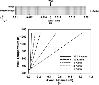 | ||
| Fig. 1 (a) Computational domain and grid details (b) wall temperature profiles for each temperature gradient case. | ||
The mesh is generated using GAMBIT with a grid-size of Δx = 25 μm, Δr = 25 μm (base grid in the flame zone) which gives a sufficient number of grid points within the flame zone with flame thickness δf = 0.39 mm, δf/Δx = 15.6. The grid in the axial direction is expanded from the inlet to 30 mm and then it is maintained uniform Δx = 25 μm upto the outlet. The grid along the radial direction is such that it is clustered towards the wall to ensure better resolution of gradients near the wall. Grids of similar sizes have been shown to provide grid-independent results by various researchers for unsteady flame propagation studies in the literature and the reported results have been shown to be grid independent.26,27 The total numbers of grid points in the meshes generated are 69![[thin space (1/6-em)]](https://www.rsc.org/images/entities/char_2009.gif) 000, 121
000, 121![[thin space (1/6-em)]](https://www.rsc.org/images/entities/char_2009.gif) 000, 241
000, 241![[thin space (1/6-em)]](https://www.rsc.org/images/entities/char_2009.gif) 000, 621
000, 621![[thin space (1/6-em)]](https://www.rsc.org/images/entities/char_2009.gif) 000 and 1
000 and 1![[thin space (1/6-em)]](https://www.rsc.org/images/entities/char_2009.gif) 221
221![[thin space (1/6-em)]](https://www.rsc.org/images/entities/char_2009.gif) 000 for temperature gradients of 33.33 K mm−1, 10 K mm−1, 5 K mm−1, 2 K mm−1 and 1 K mm−1, respectively. Fig. 2(a) shows the variation of heat release rate along the axis for the base grid (Δx = 25 μm, Δr = 25 μm) and a refined grid of Δx = 15 μm, Δr = 15 μm. It can be seen that the base grid results are completely matching with refined grid indicating that the obtained results are independent of the grid used for present studies.26 Fig. 2(b) shows the variation of flame propagation speed relative to local mixture flow velocity based on peak heat release rate along with the experimental data of Nakamura et al.19 The x-axis represents time from the start of ignition which is taken to be ≈50 K more than that of corresponding wall temperature. The propagation speed is S = u − v, where u is local mixture flow velocity (u = uo × To/T) and v = dx/dt is the velocity of propagation of heat release rate (HRR) peak. Nakamura et al.19 have reported experimental investigations on the similar configuration of 2 mm diameter tube, with inlet velocity of 0.15 m s−1 and stoichiometric methane/air mixture with wall temperature varying nearly linearly from 300 K to 1300 K (over 30 mm). Flame propagation was recorded with 8000 fps high-speed camera and uncertainty in the tracking the flame position is not presented. With all these considerations, it can be seen that computed propagation velocity match well with experimental results.
000 for temperature gradients of 33.33 K mm−1, 10 K mm−1, 5 K mm−1, 2 K mm−1 and 1 K mm−1, respectively. Fig. 2(a) shows the variation of heat release rate along the axis for the base grid (Δx = 25 μm, Δr = 25 μm) and a refined grid of Δx = 15 μm, Δr = 15 μm. It can be seen that the base grid results are completely matching with refined grid indicating that the obtained results are independent of the grid used for present studies.26 Fig. 2(b) shows the variation of flame propagation speed relative to local mixture flow velocity based on peak heat release rate along with the experimental data of Nakamura et al.19 The x-axis represents time from the start of ignition which is taken to be ≈50 K more than that of corresponding wall temperature. The propagation speed is S = u − v, where u is local mixture flow velocity (u = uo × To/T) and v = dx/dt is the velocity of propagation of heat release rate (HRR) peak. Nakamura et al.19 have reported experimental investigations on the similar configuration of 2 mm diameter tube, with inlet velocity of 0.15 m s−1 and stoichiometric methane/air mixture with wall temperature varying nearly linearly from 300 K to 1300 K (over 30 mm). Flame propagation was recorded with 8000 fps high-speed camera and uncertainty in the tracking the flame position is not presented. With all these considerations, it can be seen that computed propagation velocity match well with experimental results.
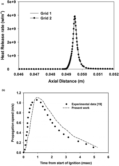 | ||
| Fig. 2 (a) Heat release rate variation along the axis for two different grids. (b) Validation of present computations with experimental work of Nakamura et al.19 for wall temperature gradient of 33 K mm−1. | ||
Combustion kinetics is modeled using detailed reaction mechanism, GRI-MECH 3.0.25 The mechanism consists of 36 species and 219 reactions (excluding NOx mechanism part, not of interest in the present work), also used by Nakamura et al.19 for their detailed 1D study. A highly nonlinear and coupled system of governing equations for mass, momentum, energy and species conservation has been solved with the help of various boundary conditions. The boundary conditions applied in the present work are
(1) Channel inlet: stoichiometric methane/air mixture with uniform velocity of 0.15 m s−1, T = 300 K.
(2) Outlet: pressure equal to atmospheric pressure.
(3) A linearly varying wall temperature profile from 300 K to 1300 K as shown in Fig. 1(b).
(4) Axisymmetric boundary condition applied to the center-line.
The details of numerical approach can also be seen elsewhere.26 A weak flame (0.01–0.05 m s−1), flame with repetitive ignition and extinction (0.05–0.38 cm s−1), and a normal flame (0.38–0.9 m s−1) have been observed experimentally inside a preheated tube. The mixture velocity was taken to be 0.15 m s−1 as the present work focuses on FREI phenomenon. A mixture velocity of 0.15 m s−1 is chosen as same conditions were experimentally investigated by Nakamura et al.19 for FREI propagation and flow is considered to be laminar as Re = 18.5. Computations performed with a fixed time step of 10 μs and 5 μs showed no significant difference in results and hence all results shown in the present work are obtained with 10 μs time step. Wall reactions have been ignored as their contributions have been found to be negligible for heated channels of similar dimensions.28 Initially, the mixture is allowed to flow into a heated tube with wall temperature gradient and when the mixture reaches higher wall temperature, it automatically ignites as the mixture reaches an autoignition temperature. To avoid the effect of initial conditions on the computational results, the results of first FREI cycle are neglected. The results for second FREI cycle are considered for further analysis and the results of later cycles agree with the results of the second cycle both quantitatively and qualitatively. The results of the first cycle of FREI are not considered as they might have the influence of the initial conditions.
3. Results and discussion
The present studies are focused on investigating the effect of wall temperature gradient on the ignition phenomenon of FREI with methane/air mixtures. The basic characteristics of ignition phenomenon in a heated channel are discussed in the first section for 33.33 K mm−1. The effect of wall temperature gradient on ignition phenomenon is thereby explained with the help of various temperature and CO/OH species profiles.3.1 Flame ignition phenomenon in a heated channel
Fig. 3(a) and (b) show the profiles of temperature and CO species at different instances in a FREI cycle for 33.33 K mm−1 wall temperature gradient case. The entire FREI propagation cycle has been divided into 5 phases, such as (i) initiation phase (0 ms), (ii) ignition phase (22.3 ms), (iii) propagation phase (27 ms), (iv) weak reaction phase (43.5 ms) and (v) flowing phase (47 ms) as already stated by Nakamura et al.19 for 1D case and Nair et al.26 for 2D case with premixed H2–air mixtures. In Fig. 3(a), the temperature plots till weak reaction phase are shown because, for flowing phase, the temperature profile becomes similar to that of initiation phase.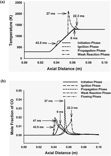 | ||
| Fig. 3 Profiles of temperature and CO species for different modes in a FREI propagation cycle with a temperature gradient of 33.33 K mm−1 (a) temperature profiles (b) CO species profiles. | ||
3.2 Ignition phenomenon for different wall temperature gradient
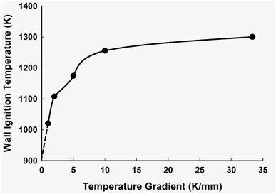
To understand the effect of wall temperature gradient on a FREI cycle, the ignition pattern of the flame needs to be understood clearly. The present study has been carried out with wall temperature gradients varying from 33.33–1 K mm−1. The higher value of the wall temperature gradient considered in present work, 33.33 K mm−1 is close to the values of temperature gradient employed by Maruta et al.4,19 in their experimental investigations.Fig. 4 shows the variation of the mixture ignition temperature with the wall temperature gradient for the range of conditions investigated in the present work. The ignition temperatures are observed to be 1300 K, 1255.5 K, 1174.2 K, 1107.2 K and 1020.45 K for 33.33 K mm−1, 10 K mm−1, 5 K mm−1, 2 K mm−1 and 1 K mm−1 temperature gradients, respectively. The mixture ignition temperature is observed to decrease with a decrease in the wall temperature gradient as shown in Fig. 4. A significant change in the point of ignition has also been observed with a reduction in temperature gradient as discussed later. As the temperature gradient decreases, the point of flame ignition moves towards a lower temperature region in order to ignite the fuel/air mixture, and the temperature required for ignition of incoming methane/air mixture is reduced. It is expected that as the wall temperature gradient is reduced to zero, the methane/air mixture will ignite at its auto-ignition temperature of ∼910 K.
Fig. 5(a) and (b) shows the heat release rate (HRR) and OH mole fraction contours at the ignition phase for various wall temperature gradients of 33.33 K mm−1, 10 K mm−1, 5 K mm−1 and 1 K mm−1 respectively. It can be seen clearly from the figure that the ignition of the flame occurs at the axis of the channel and not at the walls. This can be attributed to the boundary layer effect near the wall. It can be noted from the contours of HRR and OH mole fraction that the maximum value of HRR and OH mole fraction is for 33.33 K mm−1. As the wall temperature gradient decreases from 33.33 K mm−1 to 1 K mm−1, the HRR and OH mass fraction values reduce significantly. This is evident from the contours of HRR and OH mass fraction values shown in Fig. 5(a) and (b). It is also interesting to note that the thickness of the reaction zone increases significantly with a decrease in the wall temperature gradient indicating that ignition process occurs at a much larger channel width.
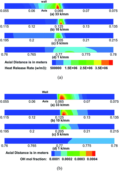 | ||
| Fig. 5 (a) Heat release rate (HRR) contour at ignition phase for different temperature gradients (b) OH mole fraction contour at ignition phase for different temperature gradient. | ||
3.3 Effect of wall temperature gradient on frequency of FREI propagation mode
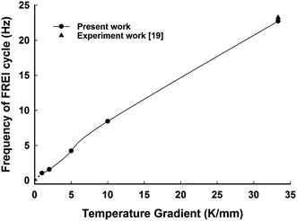
Fig. 6 shows the variation in frequency of a FREI propagation mode for different wall temperature gradients. The inverse time period of ignition of a mixture between two cycles is taken to calculate the frequency of a FREI cycle. The FREI frequency of the present work matches well with that of experimental data of Nakamura et al.19 for a wall temperature gradient of 33.33 K mm−1 as shown in Fig. 6. It is interesting to note from this figure that the frequency of the propagation of FREI mode decreases with a decrease in the wall temperature gradient. It takes longer time for the mixture to ignite as the wall temperature gradient is reduced, thus increasing the time required for completing a FREI cycle. It can be observed that the frequency of the FREI cycle reduces from 23 Hz to 1 Hz as wall temperature gradient is reduced from 33.33 K mm−1 to 1 K mm−1. It is expected that a further reduction in the wall temperature gradient towards zero would lead to the disappearance of the FREI phenomena altogether. A similar observation of disappearance of FREI phenomena has been predicted by Mazurok et al.17 in their theoretical analysis in the perspective of a thermo-diffusive model for very low wall temperature gradients. For lower values of wall temperature gradient, the flame would be sufficiently stabilized at a particular location, as mixture would continue to auto-ignite at a particular location as shown in Fig. 4.3.4 Effect of wall temperature gradient on ignition phenomenon
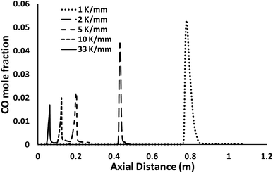
The present study focuses more on understanding the effect of wall temperature gradient on ignition phenomenon. The work studies the effect of 33.33 K mm−1, 10 K mm−1, 5 K mm−1, 2 K mm−1 and 1 K mm−1 temperature gradients for a uniform stoichiometric mixture of methane/air at 0.15 m s−1 inlet mixture velocity.Fig. 7 shows the effect of wall temperature gradient on the mole fraction of CO along the axis of the tube. The variation of CO mole fraction with wall temperature gradient will help understand the ignition phenomenon during the FREI dynamics. It can be seen from Fig. 7 that with a decrease in wall temperature gradient from 33.33 K mm−1 to 1 K mm−1, there is a significant shift in the flame ignition position towards upstream direction as ignition occurs at a lower temperature (Fig. 4). Since the corresponding wall temperature at the ignition point of the flame decreased significantly (Fig. 4) with a decrease in wall temperature gradient, the flame moves towards low-temperature region in the upstream direction. The mixture ignites at a much lower temperature. The CO mole fraction also increases with a decrease in the wall temperature gradient. Further, it is interesting to note that for 1 K mm−1 wall temperature gradient, the CO concentration increases significantly as compared to higher wall temperature gradients.
Therefore, for a very small temperature gradient, the FREI phenomenon itself may vanish since the ignition temperature of flame decreases and due to the flame movement towards the upstream side of the channel. Thus it can be prophesized that for very small temperature gradient, the ignition may occur only if the maximum temperature in the domain is higher than the auto-ignition temperature of fuel/air mixture. Further, the point of ignition and extinction are expected to coincide with each other for such a condition.
3.5 Effect of wall temperature gradient on FREI cycle
Fig. 8 shows the variation in the location of maximum CO mole fraction with respect to normalized distance along the axis. The distance along the axis is normalized for wall temperature gradient section with, xn = (x − 0.03)dT/dx. It is interesting to note that the FREI cycle significantly decreases with a decrease in the temperature gradient. The location of the ignition and extinction points comes closer to each other as temperature gradient becomes smaller. It is expected that a further reduction in the wall temperature gradient to values lower than 1 K mm−1 would lead to shrinking of the FREI cycle and complete disappearance of FREI for zero temperature gradient conditions in the tube walls. This aspects of disappearance of FREI for smaller temperature gradients is also evident from earlier Fig. 4 and 6. It is also to be noted from Fig. 7 and 8 that that the peak CO mole fraction increases with a decrease in the wall temperature gradient.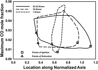 | ||
| Fig. 8 Variation of the location and magnitude of maximum CO mole fraction along the normalized axis for various wall temperature gradients. | ||
3.6 Flame bifurcation and wall temperature gradient
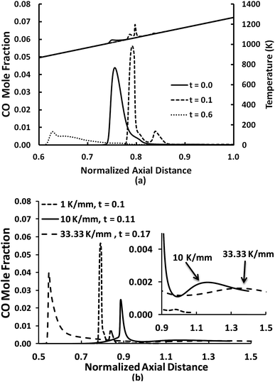
Fig. 9 shows the variation of CO mole fraction and flame temperature along the normalized axial distance for different instances of flame propagation during a FREI propagation mode for 1 K mm−1 wall temperature gradient case. It is to be noted that the mixture initially ignites at t = 0 (normalized time period with respect to FREI cycle time) and then flame moves downstream immediately. A flame bifurcation can be observed at t = 0.1, showing two distinct peaks in CO mole fraction. Followed by this, the flame propagates upstream and extinguishes at a particular location and a small peak in CO mole fraction can be observed. Fig. 9(b) shows the CO mole fraction along the axis at the point of flame bifurcation. It can be observed that flame bifurcation occurs when the flame is propagating upstream in the case of 33.33 K mm−1. However, for 1 K mm−1 case, the flame bifurcation occurs just after the ignition. Therefore, there is a significant variation in the flame bifurcation characteristics with a change in wall temperature gradient. The significant downstream movement in the flame is clearly shown in Fig. 8.3.7 Heat loss to the wall
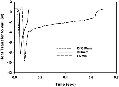
Fig. 10 shows the variation of total heat transfer from the propagating flame to the solid walls during one of the FREI cycle through the channel. The nature of profile is similar to that observed by Kang et al.29 It is to be noted that as the temperature gradient reduces, the heat loss to the wall increases significantly. For 1 K mm−1 case, heat loss is prolonged over a longer period as the flame propagates upstream from relatively low wall temperature compared to the case of higher wall temperature gradients of 10 and 33.33 K mm−1. The increased heat loss from the propagating flame to the channel walls significantly affects the flame dynamics. This results in increased CO mole fraction and reduced cycle dynamics as shown in Fig. 8 and 9. This variation in heat loss due to varying wall temperature gradients results in reduced flame-wall coupling. This reduced thermal wall coupling perhaps results in the disappearance of the FREI dynamics for very low wall temperature gradients.4. Conclusions
This paper presents the detailed numerical investigations on FREI flame propagation mode for stoichiometric methane/air mixtures with different wall temperature gradients. The wall temperature gradients are varied from 33.33 K mm−1 to 1 K mm−1 in the present computations. Five distinct FREI propagation modes have been observed during its propagation through the tube. It has been observed that the fuel/air mixture ignition temperature decreases with a decrease in the wall temperature gradient. It is expected that the methane/air mixture would ignite at autoignition temperature if the wall temperature gradient approaches zero. Further, as the wall temperature gradient decreases, the point of ignition moves in an upstream direction towards the low temperature region. It is to be noted that the ignition of fuel/air mixture occurs at the axis of the channel and not at the walls. This is due to the boundary layer phenomenon, which results in ignition at the axis of the channel. The frequency of FREI flame propagation mode has been observed to decrease with the wall temperature gradient. In a similar fashion, the points of ignition and extinction also observed to narrow down with the temperature gradient. It is expected for lower temperature gradients, the points of ignition and extinction may coincide with each other. For such conditions of the very low temperature gradient, the occurrence of FREI may completely disappear.References
- J. Maruta and Y. Ju, Microscale combustion: technology development and fundamental research, Prog. Energy Combust. Sci., 2011, 37, 669–715 CrossRef.
- A. Veeraragavan and C. Cadou, Flame speed predictions in planar micro/mesoscale combustors with conjugate heat transfer, Combust. Flame, 2011, 158, 2178–2187 CrossRef CAS.
- S. Kumar, K. Maruta and S. Minaev, Experimental investigations on the combustion behavior of methane–air mixtures in a micro-scale radial combustor configuration, J. Micromech. Microeng., 2007, 17, 900–908 CrossRef CAS.
- K. Maruta, J. K. Parc, K. C. Oh, T. Fujimori, S. S. Minaev and R. V. Fursenko, Characteristics of microscale combustion in a narrow heated channel, Combust., Explos. Shock Waves, 2004, 40, 516–523 CrossRef.
- K. Maruta, T. Kataoka, N. I. Kim, S. Minaev and R. Fursenko, Characteristics of combustion in a narrow channel with a temperature gradient, Proc. Combust. Inst., 2005, 30, 2429–2436 CrossRef.
- Y. Tsuboi, T. Yokomori and K. Maruta, Lower limit of weak flame in a heated channel, Proc. Combust. Inst., 2009, 32, 3075–3081 CrossRef CAS.
- Y. Tsuboi, T. Yokomori and K. Maruta, Extinction characteristics of premixed flame in the heated microchannel at reduced pressures, Combust. Sci. Technol., 2008, 180, 2029–2045 CrossRef CAS.
- K. Maruta, Micro and mesoscale combustion, Proc. Combust. Inst., 2011, 33, 125–150 CrossRef CAS.
- H. G. Pearlman and P. D. Ronney, Near-limit behavior of high-Lewis number premixed flames in tubes at normal and low gravity, Phys. Fluids, 1994, 6, 4009–4018 CrossRef CAS.
- V. Nayagam and F. A. Williams, Rotating spiral edge flames in von Karman swirling flows, Phys. Rev. Lett., 2000, 84, 479 CrossRef CAS PubMed.
- V. Panfilov, A. Bayliss and B. J. Matkowsky, Spiral flames, Appl. Math. Lett., 2003, 16, 131 CrossRef.
- S. Kumar, K. Maruta and S. Minaev, Pattern formation of flames in radial microchannels with lean methane–air mixtures, Phys. Rev. E: Stat., Nonlinear, Soft Matter Phys., 2007, 75, 016208 CrossRef PubMed.
- A. Fan, S. Minaev, S. Kumar, W. Liu and K. Maruta, Experimental study on flame pattern formation and combustion completeness in a radial microchannel, J. Micromech. Microeng., 2007, 17, 2398–2406 CrossRef.
- B. Xu and Y. Ju, Experimental study of spinning combustion in a mesoscale divergent channel, Proc. Combust. Inst., 2007, 31, 3285–3292 CrossRef.
- S. S. Minaev, E. V. Sereshchenko, R. V. Fursenko, A. Fan and K. Maruta, Splitting flames in a narrow channel with a temperature gradient in the walls, Combust., Explos. Shock Waves, 2009, 45, 119–125 CrossRef.
- A. Fan, S. S. Minaev, E. V. Sereshchenko, Y. Tsuboi, H. Oshibe, H. Nakamura and K. Maruta, Dynamic behavior of splitting flames in a heated channel, Combust., Explos. Shock Waves, 2009, 45, 245–250 CrossRef.
- D. B. Mazurok, R. V. Fursenko, S. S. Minaev, N. A. Lutsenko and S. Kumar, Regimes of combustion of a premixed mixture of gases in a heated microchannel with the wall temperature smoothly increasing in the downstream direction, Combust., Explos. Shock Waves, 2014, 50, 25–31 CrossRef.
- A. Veeraragavan, On flame propagation in narrow channels with enhanced wall thermal conduction, Energy, 2015, 93, 631–640 CrossRef.
- H. Nakamura, A. Fan, S. Minaev, E. Sereshchenko, R. Fursenko, Y. Tsuboi and K. Maruta, Bifurcations and negative propagation speeds of methane/air premixed flames with repetitive extinction and ignition in a heated microchannel, Combust. Flame, 2012, 159, 1631–1643 CrossRef CAS.
- H. Oshibe, H. Nakamura, T. Tezuka, S. Hasegawa and K. Maruta, Stabilized three-stage oxidation of DME/air mixture in a micro flow reactor with a controlled temperature profile, Combust. Flame, 2010, 157, 1572–1580 CrossRef CAS.
- A. Yamamoto, H. Oshibe, H. Nakamura, T. Tezuka, S. Hasegawa and K. Maruta, Stabilized three-stage oxidation of gaseous n-heptane/air mixture in a micro flow reactor with a controlled temperature profile, Proc. Combust. Inst., 2011, 33, 3259–3266 CrossRef CAS.
- G. Pizza, C. E. Frouzakis, J. Mantzaras, A. G. Tomboulides and K. Boulouchos, Dynamics of premixed hydrogen/air flames in microchannels, Combust. Flame, 2008, 152, 433–450 CrossRef CAS.
- G. Pizza, C. E. Frouzakis, J. Mantzaras, A. G. Tomboulides and K. Boulouchos, Dynamics of premixed hydrogen/air flames in mesoscale channels, Combust. Flame, 2008, 155, 2–20 CrossRef CAS.
- E. Miyata, N. Fukushima, Y. Naka, M. Shimura, M. Tanahashi and T. Miyauchi, Direct numerical simulation of micro combustion in a narrow circular channel with a detailed kinetic mechanism, Proc. Combust. Inst., 2015, 35, 3421–3427 CrossRef CAS.
- G. P. Smith, D. M. Golden, M. Frenklach, N. W. Moriarty, B. Eiteneer, M. Goldenberg, C. T. Bowman, R. K. Hanson, S. Song, W. C. Gardiner Jr, V. V. Lissianski and Z. Qin, GRI-Mech 3.0, http://www.me.berkeley.edu/gri_mech/ Search PubMed.
- A. Nair, V. R. Kishore and S. Kumar, Dynamics of Premixed Hydrogen–Air Flames in Microchannels with a Wall Temperature Gradient, Combust. Sci. Technol., 2015, 187, 1620–1637 CrossRef CAS.
- A. P. Singh, V. R. Kishore, S. S. Minaev and S. Kumar, Numerical investigations of unsteady flame propagation in stepped microtubes, RSC Adv., 2015, 5, 100879–100890 RSC.
- Y. Kizaki, H. Nakamura, T. Tezuka, S. Hasegawa and K. Maruta, Effect of radical quenching on CH4/air flames in a micro flow reactor with a controlled temperature profile, Proc. Combust. Inst., 2015, 35, 3389–3396 CrossRef CAS.
- X. Kang, J. G. Rowan, P. A. Jacobs and A. Veeraragavan, Suppression of instabilities in a premixed methane–air flame in a narrow channel via hydrogen/carbon monoxide addition, Combust. Flame, 2016, 173, 266–275 CrossRef CAS.
| This journal is © The Royal Society of Chemistry 2017 |

