 Open Access Article
Three-dimensional highly conductive silver nanowires sponges based on cotton-templated porous structures for stretchable conductors†
Chun-Hua Zhu,
Li-Ming Li,
Jian-Hua Wang,
Ye-Ping Wu* and
Yu Liu*
Institute of Chemical Materials, China Academy of Engineering Physics, Mianyang, Sichuan 621900, China. E-mail: wuyp@caep.cn; liuyu307@caep.cn; Fax: +86-816-2486342
First published on 22nd December 2016
Abstract
A stretchable cotton–Ag nanowire–poly(dimethylsiloxane) (cotton–AgNWs–PDMS) conductor was fabricated by embedding the unique binary conductive network structure of cotton–AgNWs in PDMS through a simple dip-coating method. The binary conductive network structure was constructed based on cotton which had an interconnected and junction-free macroporous structure as the skeleton to support the two dimensional AgNWs network, leading to excellent electrical and mechanical properties. The conductivity of the stretchable conductor can be adjusted easily by varying the dip-coating cycles, which can reach a highest electrical conductivity of 56.82 S cm−1. The cotton–AgNWs–PDMS composite can retain excellent conductance under large tensile strains (120%). Moreover, the excellent conductance is maintained up to 1000 stretching or bending cycles. Because of the high conductivity and excellent stretchability, together with the facile fabrication process, the cotton–AgNWs–PDMS stretchable conductor might be widely used as interconnects and electrodes for stretchable intelligent and functional devices.
1. Introduction
Stretchable conductors which can retain high conductivity under substantial stretching and bending deformation can enable a wide variety of new applications in electronic skins, camera eyes, biological actuators, sensors, and deformable capacitors.1–4 To feature both high conductivity and large deformation stability, a variety of conductive and stretchable structures such as wave structural configuration, three-dimensional (3D) conductive architectures and the formation of two-dimensional conductive network have been developed recently and embedded in the elastic polymer to address the need of stretchable conductors.4–7Among abovementioned many kinds of conductive structures, 3D conductive architectures are particularly attractive for improving the performance of the conductors because of their potentially better mechanical durability and lower cost.8,9 The shape deformation and elongation of 3D conductive structures can transfer the stress without decay in conductivity under stretching to a certain extent.3,10–12 In order to construct those 3D architectures, polymer sponges (e.g., polyurethane (PU), poly(dimethylsiloxane) (PDMS)) and Ni foam have been used as the skeleton.13–15 Stretchable conductors containing PU–AgNWs or PU–CuAg sponges as the shape deformation structure have been investigated, showing remarkable electrical and mechanical capability.8,13,16 3D flexible graphene/PDMS composite using Ni foam as template has also been reported.15 However, surface modifications of polymer sponges are always needed to increase the adhesion between conductive nanomaterials and polymer fibers, where Ni foam should be etched to obtain the porous conductive network.8,13,15,17,18 Thus the fabrication processes are always complicated. It remains challenging to simply constructing these unique 3D conductive structures into stretchable conductors, which impedes our effort in further exploring their practical ways.
As we known, cotton, a typical natural material, is low cost and sustainable, containing 90–95% cellulose.19,20 The most intriguing part of cotton is its interconnected, porous 3D framework of randomly oriented, crinkly sheets with continuous macropores, making it a promising raw skeleton for fabrication of stretchable conductors. Although hybrid conductive cotton materials has been investigated directed in the area of wearable device (electronic textiles)21,22 or used as pressure sensor,23 stretchable conductor based on cotton-templated porous structure has not been reported yet. Using cotton as the skeleton is advantageous both because its natural porous 3D framework and its hydrophilic surface property which leads good adhesion to conductive nanomaterials. Thus it is interesting to modulate the properties of flexible conductor through the incorporation of 3D conductive architectures into porous cotton skeleton.
In this paper, we report a simple, controllable, and cost-effective route for the fabrication of binary network structured cotton–Ag nanowires–poly(dimethylsiloxane) (cotton–AgNWs–PDMS) conductor through the dip-coating method. The binary network structure was constructed based on cotton with an interconnected and junction-free macroporous structure as the skeleton to support the 2D AgNWs network. The conductivity of the stretchable conductor can be adjusted easily by varying the dip-coating cycles, which can reach a highest electrical conductivity of 56.82 S cm−1. The cotton–AgNWs–PDMS composite can retain excellent conductance under large tensile strains (120%). Moreover, the excellent conductance is maintained up to 1000 stretching or bending cycles. The unique interconnected network of cotton–AgNWs–PDMS conductor provides a great potential for using conductive materials in electrical applications.
2. Results and discussion
2.1 Fabrication of stretchable conductor
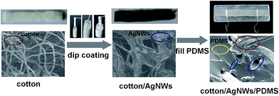
The highly stretchable PDMS conductor loaded with 3D cotton–AgNWs conductive network was successfully prepared via facile dip-coating method. The fabrication process of the cotton–AgNWs–PDMS stretchable conductor is schematically illustrated in Fig. 1. First, high-quality AgNWs were synthesized by a previously reported one-pot method.16 Then white, porous cotton with interconnected fiber network was dipped into isopropyl alcohol solution of AgNWs, where the fibers were wrapped by the AgNWs after evaporating the isopropyl alcohol resulting the color changed from white to gray. The density of AgNWs coated on the fiber can be effective adjusted by varying dip-coating cycles. As shown in Fig. 1, 3D porous AgNWs network with cotton fiber as the skeleton was clearly formed resulting in a conductive sponge. Finally, PDMS precursor was introduced into the cotton–AgNWs sponge to form the desired cotton–AgNWs–PDMS stretchable conductor, where the conductive sponge can be clearly seen embedded in PDMS. Such a convenient fabrication procedure can be extended for efficient construction of conductive patterns.As previously reported, the concentration of conductive nanomaterials in polymer can be used to control the changes of the deformation-induced resistance effectively.16,24 In our cotton–AgNWs composite conductor system, the AgNWs were expected to have the same effect, endowing additional tunability to the amplitude of deformation in conductive network, and to the subsequent resistance variation. As shown in Fig. 2a, the porous cotton sheets were composed of twisted cotton fibers with a diameter of 10–20 μm. The pristine cotton fibers were smooth, while AgNWs were clearly observed on the surface of cotton fiber after dip-coating process. SEM images showed that the cotton–AgNWs composite exhibited an interconnected, porous 3D framework of randomly oriented, crinkly sheets with continuous macropores, similar to those of previous conductive networks.25–27 The change of porosity of cotton before and after dip-coating was unobvious. As shown in Fig. 2b–d, the density of AgNWs on the surface of the fibers increased with the times of dip-coating, indicating an increased conductivity, which was verified by the increased mass fraction of AgNWs as shown later.
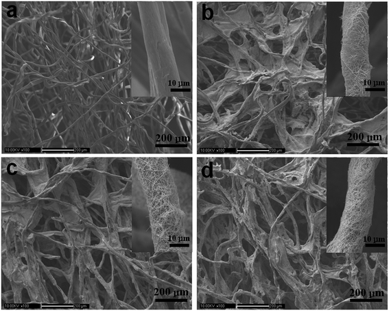 | ||
| Fig. 2 SEM images of (a) cotton and cotton–AgNWs composites prepared by dipping cotton into an isopropanol solution of AgNWs (5.7 mg mL−1) for (b) one, (c) two, (d) three times, respectively. | ||
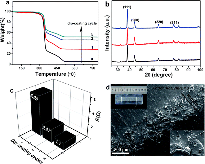
As shown in Fig. 3a, the mass fraction of AgNWs increased sharply as dip-coating cycles increased. For example, the content of AgNWs in the cotton–AgNWs composites rose from 23.3% to 46.6% as the dip coating times increased from one to three. Fig. 3b shows the XRD patterns of cotton–AgNWs prepared with various dip-coating cycles. The typical diffraction peaks appeared centered at 2θ = 38.10, 44.20, 64.34, and 77.39° were ascribed to Bragg reflections from the (111), (200), (220), (311) planes of Ag, which indicates the existence of Ag in the composites respectively.28,29
The solution dip-coating method used for tuning the conductivity was also verified by the resistance of the cotton–AgNWs–PDMS composites (Fig. 3c). The resistance of cotton–AgNWs–PDMS stretchable conductor was decreased sharply from 6.09 Ω to 1.10 Ω as the times of dip-coating cycle increased from one to three, which demonstrated that cotton–AgNWs–PDMS composites with different conductivity can be obtained by simply tuning the dip-coating cycle times through controlling the density of the AgNWs coating on the surface of the cotton fiber network. In addition, the resistances of cotton–AgNWs–PDMS composites remain nearly unchanged after infiltrated by PDMS, which suggests that introduction of the PDMS matrix does not damage the interconnected 3D scaffold of cotton–AgNWs. The cross-sectional SEM image of the resulting cotton–AgNWs–PDMS conductor was shown in Fig. 3d. The thickness of the cotton–AgNWs composite was around 800 μm, which exhibited an entangled, randomly oriented 3D network embedded in PDMS matrix (Fig. 3d inset). The size of cotton–AgNWs sponges embedded in PDMS between two Ag wires for all measured samples is around 5.0 × 1.0 × 0.08 cm3.
2.2 Stretchability and bendability of cotton–AgNWs–PDMS conductor
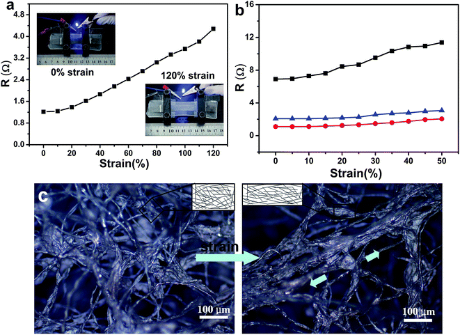
The electrical conductivity of the cotton–AgNWs–PDMS conductor prepared with one dip-coating cycle was around 10.26 S cm−1, and further increased to 56.82 S cm−1 with three dip-coating cycles. The resulted conductivity is higher than that of previous reported PUS–AgNWs–PDMS conductor after eight dip-coating cycles or AgNWs/PDMS conductor prepared by ice templating, furthermore, the procedure here is much easier.10,16 As reported previously, the electrical conductivity of the cotton-based conductive materials (e.g. cotton/SWCNT) increases obviously with mechanical pressing.23,30 These results indicate that the unique interconnected network of cotton-based composite provides electromechanical properties. Here, the stretchable properties of cotton templated composites were investigated. Cotton–AgNWs–PDMS composites were stretched by a home-made equipment, while the electric resistance was measured at the same time. As shown in Fig. 4a, the resistances of stretchable conductor prepared with three dip-coating cycles were studied as a function of uniaxial tensile strain. It can be seen that the electric resistance increased almost linearly from 1.20 to 4.21 Ω when the tensile strain increased from 0% to 120%, where the composite retained conductive. In addition, the resistance increment (ΔR/R0) of cotton–AgNWs–PDMS conductor at 100% strain was about 180%, which is much better compared to the AgNWs–PDMS film (360% at 80% strain)31 and graphene foam–PDMS (ca. 210% at 95% strain).15 Fig. 5 clearly exhibited the stretching process and showed the resistance of cotton–AgNWs–PDMS composite under specific tensile strain (ca. from 0% to 125%) measured using a Keithley 2700 multimeter with a four-probe method, indicating that the composite retain excellent conductance under large tensile strain.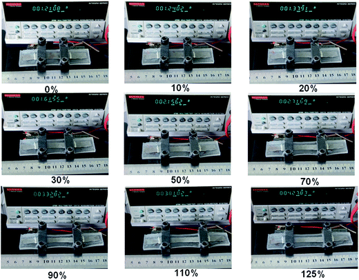 | ||
| Fig. 5 Pictures showing the resistance variation of cotton–AgNWs–PDMS conductor prepared by three dip-coating cycles at different strain during the 1st stretching. | ||
The resistances of stretchable conductors prepared with different dip-coating cycles were also investigated as a function of tensile strain from 0% to 50%. As shown in Fig. 4b, the resistance decreased rapidly when the dip-coating cycles was increased. That's because the increase of the density of AgNWs percolating networks on the cotton fiber with the dip-coating cycles which was shown in Fig. 2. The cotton fiber was almost completely covered by the conductive network of AgNWs after 3 dip-coating cycles. Moreover, with more dip-coating cycles, the resulted stretchable conductor was more stable during the stretching process. The results show that the electrical conductivity has a close relationship with the unique microstructures of 3D cotton–AgNWs networks.
To further explain the function of the unique porous structure, the deformation of this architecture under stretching was observed using optical microscope. A binary network, including an interconnected cotton network at the microscale and AgNWs network at the nanoscale was observed in Fig. 4c. As the tensile strain on cotton–AgNWs increased, randomly oriented, crinkly cotton fibers were elongated in the direction of the tensile force (marked by the arrow). And the macropores of cotton–AgNWs network also shrank perpendicular to the direction of the applied force. The shape deformation of porous 3D framework during stretching guarantees the continuity of the conductive network, which keeps the AgNWs in contact and protects them from quick disconnection. Meanwhile, an interconnected AgNWs network at the nanoscale (Fig. 4c inset) can also effectively accommodate the deformation without a noticeable decrease in conductivity to a certain extent under stretching.10,16 Thus the binary network architecture could offer the excellent advantage of structural stability under a certain extent of deformation, which results in improved electrical and mechanical performance.
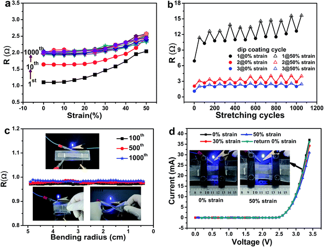
More stretching cycles in the range of 0% to 50% strain were performed to investigate its reversibility. As revealed in Fig. 6a, the resistance of the cotton–AgNWs–PDMS composite prepared with three dip-coating cycles increased with increasing tensile strain during the initial several cycles of stretching, but the amplitude of resistance variation became less as the stretching cycles increased. From the 50th cycle of stretching, the electrical resistance was restored to a constant when the stretching was released, with resistance increase of about 0.5 Ω under 50% strain, and remained unchanged for more stretching cycles within the strain range of 0% to 50%. Even at up to 1000 stretching cycles, the resistance variation curve was overlapped with the one at 50th cycle of stretching. The resistances during of the stretching-releasing process and at different stretching cycles (after 50th cycles) almost kept stable, indicating that this conductor can be used as ideal interconnects in flexible electronic applications. The irreversible resistance increase between initial condition and after 50th cycles of stretching under zero strain was about 0.8 Ω and became larger for the stretchable conductors prepared with fewer dip-coating cycles (Fig. 6b), indicating that the increase in resistance can be reasonably attributed to the partial irreversible separation of the AgNWs in the network during the stretching deformation.10,15
The effect of bending on the electrical resistance of the composite prepared with three dip-coating cycles was investigated. Cotton–AgNWs–PDMS conductor was bent to different radius of curvatures until the samples were folded. As revealed in Fig. 6c, the electrical resistance variation curve was very flat at 100th cycle and shows a constant value until the samples were folded. Even at up to 1000 bending cycles, no obvious resistance change was observed. The LED showed no noticeable change in illumination intensity while the cotton–AgNWs–PDMS conductor was folded or twisted (Fig. 6c inset). These results demonstrated the outstanding electromechanical stability of cotton–AgNWs–PDMS conductor and its great potential for high-performance stretchable conductors.
To test the cotton–AgNWs–PDMS conductor as stretchable conductors, a LED was illuminated with the as-made flexible conducting ribbon as electrical wires and the current–voltage (I–V) curves were measured when the ribbon was under tensile strain of 0%, 30% and 50% (Fig. 6d). At all stages, the LED is turned on at 2.5 V. The current decreased from 29.7 mA to 24.6 mA (at 3.3 V) when the ribbon was stretched to 50% strain. The pictures (Fig. 6d, insets) also showed that the brightness of the LED lights exhibited almost no change as cotton–AgNWs–PDMS conductor was stretched to a strain of 50% under constant voltage. These results indicate that the as-made flexible conductor could maintain constant resistance with different voltages applied while enduring 50% tensile strain. As expected, the I–V characteristics almost completely recovered when the stress was released.
3. Conclusion
In summary, a simple, cost-effective route for the preparation of cotton–AgNWs–PDMS stretchable conductor was explored through the dip-coating method. The combination of an interconnected porous structure of cotton as skeleton with supported 2D AgNWs networks leads to excellent electrical and mechanical properties, where the conductivity of stretchable conductor can be adjusted easily by varying the dip-coating cycles. The stretchable conductor can reach a highest electrical conductivity of 56.82 S cm−1, which can retain excellent conductance under large tensile strains (120%). Moreover, the stretchable conductor shows well stretchable and reversible electrical behaviors. Because of the high conductivity and excellent stretchability, together with the facile fabrication process, the cotton–AgNWs–PDMS stretchable conductor might be widely used as interconnects and electrodes for stretchable intelligent and functional devices.4. Experimental section
4.1 Materials
Silver nitrate (AgNO3), polyvinylpyrrolidone (PVP, K30), sodium chloride and isopropyl alcohol (IPA) was obtained from Sinopharm. High-purity silver paste was purchased from SPI. PDMS (Sylgard 184) was received from Dow Corning. All of the reagents were used as received without further purification.4.2 Preparation of cotton–AgNWs
AgNWs were synthesized according to the method reported previously.16 Ag nanowires were dispersed in isopropanol. The cotton was cut into small pieces with thickness of ∼1 mm and width by length of 1 × 8 cm2. All pieces were dipped into the isopropanol solution of AgNWs (∼5.7 mg mL−1) prepared by the above method, then picked out and transferred into a dry oven at 100 °C for 2 h. The different composites were prepared by varying the dip-coating cycles.4.3 Preparation of cotton–AgNWs–PDMS stretchable conductor
Ag wires were embedded and connected to the as-prepared conductors with silver paste. The distance between two Ag wires was 5 cm. Precured PDMS (mixing the “base” and the “curing agent” with a ratio of 10![[thin space (1/6-em)]](https://www.rsc.org/images/entities/char_2009.gif) :
:![[thin space (1/6-em)]](https://www.rsc.org/images/entities/char_2009.gif) 1) were poured into the as-prepared cotton–AgNWs pieces, followed by degassing in vacuum oven for 30 min and thermally curing in a dry oven at 100 °C for 2 h. Then cotton–AgNWs–PDMS composites were obtained through peeling off the films from the tailor-made moulds. The size of cotton–AgNWs embedded in PDMS between two Ag wires is 5.0 × 1.0 × 0.1 cm3, which is the same for all measured samples.
1) were poured into the as-prepared cotton–AgNWs pieces, followed by degassing in vacuum oven for 30 min and thermally curing in a dry oven at 100 °C for 2 h. Then cotton–AgNWs–PDMS composites were obtained through peeling off the films from the tailor-made moulds. The size of cotton–AgNWs embedded in PDMS between two Ag wires is 5.0 × 1.0 × 0.1 cm3, which is the same for all measured samples.
4.4 Electronic measurement
Stretching tests were conducted using a home-made equipment. For resistance measurement, Ag wires were embedded into the composites with silver pastes, and were used as leads for all measurements. The electrical resistance of the film during tensile or bending testing was measured using a Keithley 2700 multimeter in a 4-point probe method setup under ambient condition. I–V characterization was measured by Keithley 2450 multimeter.For the stretchable circuit device experiment, a simple circuit consisting of commercially available light-emitting diode (LED) and battery was fabricated. Cotton–AgNWs–PDMS film was used as electrical wires in the circuit. Moreover, a LED was also conducted in the circuit during the I–V characterization using Keithley 2450 multimeter.
4.5 Characterization
The surface morphologies of the samples were characterized using a CAMSCAN APOLLO 300 field-emission scanning electron microscope (SEM). The X-ray diffraction (XRD) patterns of the samples were obtained using a Bruker D8 X-ray diffractometer with Cu Kα irradiation at λ = 0.15418 nm. The optical images of cotton, cotton–AgNWs and cotton–AgNWs–PDMS sponge were obtained on a Zess Axio Scope A1 microscope. Thermogravimetric analysis was carried out from 50 °C to 800 °C on a Mettler TGA1 instrument under nitrogen atmosphere at a heating rate of 10 °C min−1.Acknowledgements
This work is financially supported by the National Natural Science Foundation of China (Grants No. 21407134, 21404094, 51273183, 11372290).References
- K. Xie and B. Wei, Adv. Mater., 2014, 26, 3592 CrossRef CAS PubMed.
- M. L. Hammock, A. Chortos, B. C. Tee, J. B. Tok and Z. Bao, Adv. Mater., 2013, 25, 5997 CrossRef CAS PubMed.
- S. Yao and Y. Zhu, Adv. Mater., 2015, 27, 1480 CrossRef CAS PubMed.
- T. Cheng, Y. Zhang, W. Y. Lai and W. Huang, Adv. Mater., 2015, 27, 3349 CrossRef CAS PubMed.
- Y. Tang, S. Gong, Y. Chen, L. W. Yap and W. Cheng, ACS Nano, 2014, 8, 5707 CrossRef CAS PubMed.
- M. K. Shin, J. Oh, M. Lima, M. E. Kozlov, S. J. Kim and R. H. Baughman, Adv. Mater., 2010, 22, 2663 CrossRef CAS PubMed.
- F. Xu, X. Wang, Y. Zhu and Y. Zhu, Adv. Funct. Mater., 2012, 22, 1279 CrossRef CAS.
- Y. Yu, J. Zeng, C. Chen, Z. Xie, R. Guo, Z. Liu, X. Zhou, Y. Yang and Z. Zheng, Adv. Mater., 2014, 26, 810 CrossRef CAS PubMed.
- M. Chen, L. Zhang, S. Duan, S. Jing, H. Jiang and C. Li, Adv. Funct. Mater., 2014, 24, 7548 CrossRef CAS.
- H. L. Gao, L. Xu, F. Long, Z. Pan, Y. X. Du, Y. Lu, J. Ge and S. H. Yu, Angew. Chem., Int. Ed., 2014, 53, 4561 CrossRef CAS PubMed.
- J. Zhi, W. Zhao, X. Liu, A. Chen, Z. Liu and F. Huang, Adv. Funct. Mater., 2014, 24, 2013 CrossRef CAS.
- Y. R. Jeong, H. Park, S. W. Jin, S. Y. Hong, S. S. Lee and J. S. Ha, Adv. Funct. Mater., 2015, 25, 4228 CrossRef CAS.
- L. M. Li, C. H. Zhu, Y. P. Wu, J. H. Wang, T. L. Zhang and Y. Liu, RSC Adv., 2015, 5, 62905 RSC.
- G. S. Jeong, D. H. Baek, H. C. Jung, J. H. Song, J. H. Moon, S. W. Hong, I. Y. Kim and S. H. Lee, Nat. Commun., 2012, 3, 977 CrossRef PubMed.
- Z. P. Chen, W. C. Ren, L. B. Gao, B. L. Liu, S. F. Pei and H. M. Cheng, Nat. Mater., 2011, 10, 424 CrossRef CAS PubMed.
- J. Ge, H. B. Yao, X. Wang, Y. D. Ye, J. L. Wang, Z. Y. Wu, J. W. Liu, F. J. Fan, H. L. Gao, C. L. Zhang and S. H. Yu, Angew. Chem., Int. Ed., 2013, 52, 1654 CrossRef CAS PubMed.
- C. Wu, L. Fang, X. Huang and P. Jiang, ACS Appl. Mater. Interfaces, 2014, 6, 21026 CAS.
- M. Chen, S. Duan, L. Zhang, Z. H. Wang and C. Z. Li, Chem. Commun., 2015, 51, 3169 RSC.
- (a) H. Bi, Z. Yin, X. Cao, X. Xie, C. Tan, X. Huang, B. Chen, F. Chen, Q. Yang, X. Bu, X. Lu, L. Sun and H. Zhang, Adv. Mater., 2013, 25, 5916 CrossRef CAS PubMed; (b) H. Bi, X. Huang, X. Wu, X. Cao, C. L. Tan, Z. Y. Yin, X. H. Lu, L. Sun and H. Zhang, Small, 2014, 10, 3544 CrossRef CAS PubMed.
- O. Carmody, R. Frost, Y. F. Xi and S. Kokot, Surf. Sci., 2007, 601, 2066 CrossRef CAS.
- P. Hu, H. Wang, Q. Zhang and Y. Li, J. Phys. Chem. C, 2012, 116, 10708 CAS.
- D. P. Hansora, N. G. Shimpi and S. Mishra, RSC Adv., 2015, 5, 107716 RSC.
- Y. Wei, S. Chen, Y. Lin, X. Yuan and L. Liu, J. Mater. Chem. C, 2016, 4, 935 RSC.
- Y. Cheng, R. Wang, J. Sun and L. Gao, ACS Nano, 2015, 9, 3887 CrossRef CAS PubMed.
- Q. Peng, Y. Li, X. He, X. Gui, Y. Shang, C. Wang, C. Wang, W. Zhao, S. Du, E. Shi, P. Li, D. Wu and A. Cao, Adv. Mater., 2014, 26, 3241 CrossRef CAS PubMed.
- Z. Niu, H. Dong, B. Zhu, J. Li, H. H. Hng, W. Zhou, X. Chen and S. Xie, Adv. Mater., 2013, 25, 1058 CrossRef CAS PubMed.
- Y. Yu, Y. Zhang, K. Li, C. Yan and Z. Zheng, Small, 2015, 11, 3444 CrossRef CAS PubMed.
- C. Zhang, K. Lv, N. Hu, L. Yu, X. Ren, S. Liu and S. Yu, Small, 2012, 8, 2936 CrossRef CAS PubMed.
- J. Chen, H. Bi, S. Sun, Y. Tang, W. Zhao, T. Lin, D. Wan, F. Huang, X. Zhou, X. Xie and M. Jiang, ACS Appl. Mater. Interfaces, 2013, 5, 1408 CAS.
- L. Hu, M. Pasta, F. L. Mantia, L. F. Cui, S. Jeong, H. D. Deshazer, J. W. Choi, S. M. Han and Y. Cui, Nano Lett., 2010, 10, 708 CrossRef CAS PubMed.
- F. Xu and Y. Zhu, Adv. Mater., 2012, 24, 5117 CrossRef CAS PubMed.
Footnote |
| † Electronic supplementary information (ESI) available. See DOI: 10.1039/c6ra25260e |
| This journal is © The Royal Society of Chemistry 2017 |

