Sound transmission loss of hierarchically porous composites produced by hydrogel templating and viscous trapping techniques
Benjamin R.
Thompson
 a,
Brogan L.
Taylor
 a,
Qin
Qin
 b,
Simeon D.
Stoyanov
 cde,
Tommy S.
Horozov
 a and
Vesselin N.
Paunov
 *a
*a
aSchool of Mathematics and Physical Sciences (Chemistry), University of Hull, Hull, UK. E-mail: V.N.Paunov@hull.ac.uk; Tel: +44 1482 465660
bThe Acoustics Research Centre, School of Engineering and Computer Science, University of Hull, Hull, HU6 7RX, UK
cUnilever R&D Vlaardingen, Olivier van Noortlaan 120, 3133 AT Vlaardingen, The Netherlands
dLaboratory of Physical Chemistry and Soft Matter, Wageningen University, 6703 HB Wageningen, The Netherlands
eDepartment of Mechanical Engineering, University College London, Torrington Place, London WC1E 7JE, UK
First published on 20th October 2017
Abstract
We have developed two different methods for fabrication of hierarchically porous composites which are environmentally friendly, inexpensive and give a large amount of control over the composite microstructure. The hydrogel bead templating method involved introducing a slurry of hydrogel beads as templates into a gypsum slurry that, upon drying, left pores reflecting their size. The overall porosity reflected the volume percentage of hydrogel bead slurry used. Using mixtures of large and small hydrogel beads in controlled volume ratios as templates, we produced hierarchically porous gypsum composites that had tailorable microstructures at the same overall porosity. The viscous trapping method involved utilisation of an aqueous solution of a thickening agent, methylcellulose, during the setting process of an aqueous gypsum slurry. The methylcellulose solution traps the hydrated gypsum particles in solution and stops their sedimentation as the continuous gypsum network forms, allowing formation of an expanded microstructure. This method allows a good degree of control over the porosity which is directly controlled by the volume percentage of methylcellulose solution used. The mechanical strength of the porous composites decreased as the porosity increased. The composites with smaller pores had increased compressional strength and Young's modulus compared to the ones produced with large pores, at constant porosity. The hierarchically porous gypsum composites showed an intermediate Young's modulus and an increased compressional strength. We also studied the sound transmission loss of these hierarchically porous composites. We found that the ones produced by the viscous trapping method had a lower sound transmission loss over the frequency range investigated as the overall porosity was increased. We demonstrated the effect of the composite pore size at a constant porosity on the sound transmission loss. Our experiments showed that porous composites with large pores showed increased sound transmission loss at lower sound frequencies compared to those with small pores. As the sound frequency increased, the difference between their STL spectra decreased and at the higher frequency range (>2420 Hz) the composites with smaller pores began to perform better. The hierarchically porous composite had an intermediate STL spectrum, suggesting a way of tailoring the hierarchically porous structure at constant porosity to achieve desired sound insulating properties at certain frequencies.
1. Introduction
Noise pollution is becoming a major problem due to the rapidly increasing population leading to people living in close proximity with each other. The use of machinery to automate or assist many processes as society advances also contributes to exposing noise to undefended ears.1 Severe health hazards have been attributed to noise pollution such as ischemic heart disease, hypertension, hearing loss and depression.2–4 These issues have necessitated the investigation of both the sound absorption and sound insulation properties of a variety of materials. Foams with an open porous structure have been used extensively for sound absorption.5 It has been shown that introducing open porosity into a material will increase its sound absorption coefficient especially at higher frequencies.6–9Sound absorption and sound insulation are significantly different acoustical concepts. Sound absorption accounts for the sound energy loss due to viscous friction and thermal effects within the material while sound insulation is due to the prevention of the transmission of sound waves through the material.10–12 Due to mass and stiffness laws, porous materials alone are less used for sound insulation. They are, however, used as centre pieces between two dense, stiff materials in a sandwich-type structure.13,14 Composite materials have been studied for their sound insulating properties, often being a material with a filler encased within.15 A recent study showed that the addition of mica platelets to poly(vinyl chloride) (PVC) foams affected the transmission of sound through the composite. During formation of the PVC foam, when the pore density became high enough, an ordering of the mica along the walls of the pores occurred, significantly increasing the sound insulating properties of the composite.16
In general, there have been two methods to determine the sound insulating properties of a material. The first method requires two adjacent rooms; one where sound is generated and transmitted through a wall containing the sample under investigation and a second room where the sound power is measured. The sound power is also measured in the first room, thereby allowing the sound transmission loss (STL) to be calculated.17 Although conceptually simple, this method suffers from multiple drawbacks, such as it being time consuming, expensive and requiring a large sample. The second method uses a four microphone impedance tube that has been developed for the measurement of STL. It is cheap and allows rapid measurements, and the sample only needs to be as wide as the tube (generally not more than 10 cm).18
Hydrogels are 3D hydrophilic, polymeric networks that have the ability to be swollen with large amounts of water. Their properties are also highly tailorable by varying the polymer concentration or concentration of cross-linking agents, or by combining two or more polymers into a hybrid hydrogel with new properties.31 They have been exploited in areas such as porogenic materials,19 drug delivery and wound dressings,20 tissue engineering21 and food structuring.22,30
Recently, a hydrogel bead templating technique has been described as a cheap, easy and environmentally friendly method for the fabrication of a variety of porous materials with precise control of the porosity and the pore size.19 It involved blending hydrogels into hydrogel beads of desired size which are then used as templates for structuring other materials. A slurry of these beads was then mixed with a templating material (e.g. cements, gypsum, clay, resins, etc.) before curing. After solidification of the surrounding matrix around the templates, the material is dried and the water is evaporated from the hydrogel bead templates, thus leaving pores in their place that reflect the size of the beads used. The porosity reflects the volume percentage of the hydrogel beads used. This only works when water is able to leave the system through open pores.
Here, we have extended this method to prepare hierarchically porous gypsum composites through the use of two different average sizes of hydrogel beads. This allowed, at constant porosity, control over the volume ratio of the large-to-small pores within the material. We have also developed an alternative viscous trapping method for controlling the porosity of gypsum through mixing a gypsum slurry with a controlled volume percentage of thickener solution, e.g. an aqueous solution of methylcellulose (MC). By mixing gypsum slurry with MC solution during the setting process, the hydrated gypsum particles were kept suspended in solution due to the high viscosity of the aqueous MC solution. This allowed the diluted gypsum slurry to form an expanded network and harden which gave higher porosity of the material. Simple dilution of the slurry with water does not work well in this case, as the gypsum particles would sediment due to gravity. Both the hydrogel bead templating method and the viscous trapping method can be used to prepare a range of hierarchically porous materials that follow a similar setting process in aqueous solution.
In the current study we have explored how the sound transmission loss and mechanical properties of hierarchically porous gypsum composites vary with pore volume fraction and pore size distributions.
2. Experimental
2.1. Materials
Gypsum powder (CaSO4·0.5H2O, with less than 3% crystalline silica impurities, Lafarge Prestia) was purchased from Fred Aldous: art, design and craft supplies. Agar was purchased from Special Ingredients and MC (A4M, food grade) was a gift from The Dow Chemical Company, Germany. Deionised water was obtained using a Milli-Q purification system (Millipore) and used in all experiments.2.2. Preparation of hydrogel beads and MC solution
To prepare agar hydrogel (2.0% w/v), water was heated to 97 °C using a water bath, followed by addition of the agar powder. It was homogenised with an Ultra-turrax homogeniser for 15 min whilst being covered with aluminium foil to minimise water loss through evaporation. After removal from the water bath and setting at room temperature, the hydrogel was left in the fridge (4 °C) overnight to set. It was then transferred to a food blender (Tefal food processor Minipro) with three stacked blades and blended at full power for either 10 seconds to produce ‘large beads’ or 600 seconds to produce ‘small beads’. MC solution (0.5% w/v) was prepared by adding the appropriate mass of MC powder to cold water whilst homogenising. To ensure complete hydration of the MC in solution, it was placed in a fridge (4 °C) overnight, then brought to room temperature before use.2.3. Production of porous and hierarchically porous gypsum composites
Gypsum slurry was prepared by mixing gypsum powder with water in the mass ratio 1.45![[thin space (1/6-em)]](https://www.rsc.org/images/entities/char_2009.gif) :
:![[thin space (1/6-em)]](https://www.rsc.org/images/entities/char_2009.gif) 1. This slurry was then mixed with the hydrogel bead slurry or with an MC solution with controlled volume percentage. The volume percentage of MC solution used to prepare the composites was either 0%, 15%, 30% or 50%. When using hydrogel beads for the preparation of porous gypsum composites, the overall volume percentage used was 40%. These were either small or large beads, or small and large beads mixed in a volume ratio of 1
1. This slurry was then mixed with the hydrogel bead slurry or with an MC solution with controlled volume percentage. The volume percentage of MC solution used to prepare the composites was either 0%, 15%, 30% or 50%. When using hydrogel beads for the preparation of porous gypsum composites, the overall volume percentage used was 40%. These were either small or large beads, or small and large beads mixed in a volume ratio of 1![[thin space (1/6-em)]](https://www.rsc.org/images/entities/char_2009.gif) :
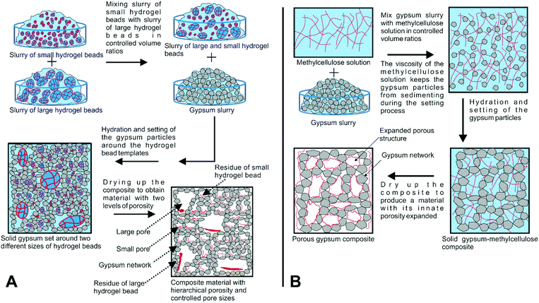
:![[thin space (1/6-em)]](https://www.rsc.org/images/entities/char_2009.gif) 1. Once mixed, they were poured into cylindrical moulds (76 mm inner diameter, 20 mm height) and allowed to cure at room temperature for 1 hour. Subsequently, they were transferred to an oven (40 °C) and dried until they reached a constant mass. Schematics of these two methods can be seen in Fig. 1A and B.
1. Once mixed, they were poured into cylindrical moulds (76 mm inner diameter, 20 mm height) and allowed to cure at room temperature for 1 hour. Subsequently, they were transferred to an oven (40 °C) and dried until they reached a constant mass. Schematics of these two methods can be seen in Fig. 1A and B.
2.4. Acoustical analysis
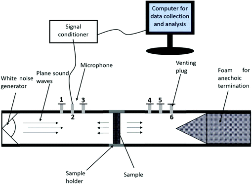
An impedance tube was designed and produced in-house according to ASTM E2611-09. Briefly, a cylindrical aluminium tube with an internal diameter of 76.2 mm and a wall thickness of 12.7 mm was used. The cut-off frequency of the tube was 2600 Hz. Four spaces for microphones were made that had a spacing of 50 mm and the distance from the sample to the closest microphone on each side was 65 mm. An anechoic termination in the form of a 400 mm long foam cylinder was placed in the downstream region, topped with a wedge that had an angle of 28° which has been shown to produce the best sound absorbing properties.23 In order to allow the full development of plane waves within the impedance tube, the distance between the sound source and the first microphone was fixed at 250 mm. White noise was generated in the upstream tube and we used a single microphone (type 4939-L-002 ¼ inch free-field microphone with a type 2669-L preamplifier, purchased from Bruel & Kjaer (B&K)) to measure the sound pressures at four different locations in the impedance tube. The holes that did not contain the microphone were plugged. Each sample was moulded into dimensions that were a close fit in the sample holder, and petroleum jelly (Vaseline) was used when mounting the sample to stop any sound pressure leakage.24 We also used venting plugs at each side of the impedance tube that were removed during sample mounting and then replaced during the testing. This prevented any displacement of the sample after mounting due to compression of air when fitting the sample holder into the tube. The procedure utilises a transfer matrix method for the calculation. Sound pressures over time during the experiments were measured at four different locations; two upstream and two downstream of the sample. The data was collected using VirtualBench-Scope 2.6 software. These sound pressures, along with a reference signal from the sound source, were used to calculate four complex transfer functions, which were then used to determine the STL. Each STL spectrum presented is an average of 10 runs. A schematic of the impedance tube setup is shown in Fig. 2.2.5. Mechanical properties
A Lloyds LS100 testing apparatus was used to study the mechanical properties of the porous gypsum composites and the gypsum control sample. The samples were subject to a 10 N preload and compressed at a rate of 4 mm min−1. The compressional strength was taken as the stress at structural failure and the Young's modulus was determined from the gradient of the linear region of the stress/strain curve.2.6. Image analysis
Hydrogel beads were dispersed in water and then viewed with an optical microscope for size distribution analysis. Images were taken in bright field light using an Olympus BX-51 optical microscope fitted with a DP70 CCD camera. The size analysis of 150 hydrogel beads at each blending time was done using ImageJ software. The porous gypsum composite samples and the gypsum control sample were left uncoated and visualised using a Hitachi TM-1000 scanning electron microscope.3. Results and discussion
3.1. Size distributions of hydrogel beads
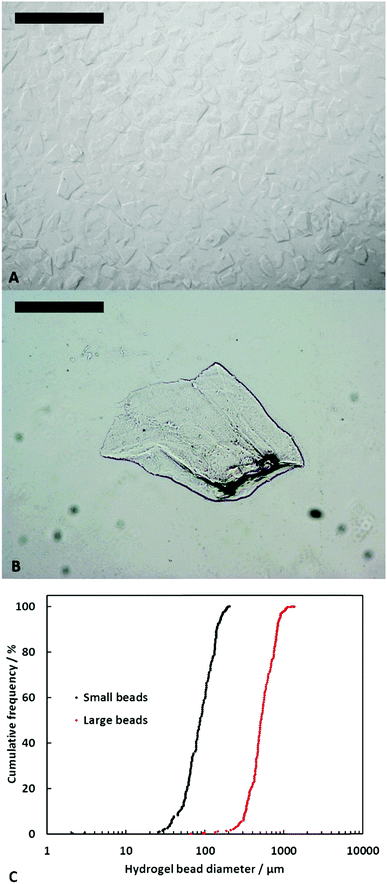
In order to investigate the effect of the pore size on the sound insulating properties of porous gypsum, we had to be able to control the size distributions of the hydrogel bead templates used during the fabrication of the porous gypsum composites. This was important as the average size of the hydrogel bead templates used determines the average size of the pores in the dried composites. The agar hydrogel was blended for different durations between 10–600 seconds and their size distributions were obtained by analysing optical images of hydrogel beads dispersed in water. Visualising the hydrogel beads dispersed in water also gives an accurate representation of their sizes as it is known that agar hydrogel does not significantly swell when dispersed in water.25 It was found that blending for 10 seconds produced hydrogel beads with an average size of 600 ± 300 μm while after blending for 600 seconds, hydrogel beads with an average size of 100 ± 50 μm were obtained. In our further experiments, these two size distributions of hydrogel beads will be referred to as ‘large beads’ and ‘small beads’, respectively. As the shape of the beads was irregular due to their preparation method, they were measured horizontally through the widest section. The cumulative hydrogel bead size distributions after blending for 10 or 600 seconds, along with optical microscopy images showing their morphology are presented in Fig. 3.3.2. Porous gypsum composites
After the composite samples were dried to a constant mass, they were weighed and their dimensions were measured. The volume and density of each sample was compared to a gypsum control sample that was produced without any hydrogel beads or MC solution. This allowed us to obtain the porosity and the reduction in volume of the porous gypsum composites. As hardened gypsum plaster itself is a porous material,26 the porosity we have reported is, in fact, the reduction in density when compared to the gypsum control sample. It was calculated using the following equation: | (1) |
The reduction in sample volume Vred (%) upon drying of the gypsum–hydrogel composite was calculated as follows:
 | (2) |
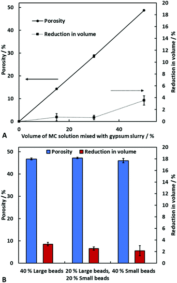
Fig. 4A shows the porosity and the reduction in volume of the porous gypsum composites produced using different volume percentages of MC solution after drying. The composites produced by the hydrogel templating technique all were done with the same volume percentage of hydrogel beads; only the volume ratio of large to small beads was varied.
Fig. 4B shows that the porosity and the reduction in volume are not significantly influenced by the variation in size of the hydrogel beads used. In Fig. 4A one can see that the porosity is directly controlled by the volume percentage of MC solution used during the sample formulation. When using 50% by volume of MC solution, the porosity of the gypsum composite after drying is approximately 50%. Furthermore, the reduction in volume is not significant (<4%) for all porous composites.
The porosity and reduction in volume for the porous and hierarchically porous gypsum composites produced by templating of slurries of hydrogel beads are shown in Fig. 4B. This shows that at constant overall volume percentage of hydrogel beads, the size distribution of the beads or the volume ratio of large beads to small beads has no effect on the porosity. Again, the volume reductions are insignificant.
When using a slurry of hydrogel beads to produce the porous gypsum, the method works by dispersing hydrogel beads in gypsum slurry which will then set around them. Upon drying of the composites, the evaporation of water from the hydrogel beads will leave pores that reflect the size and morphology of the hydrogel beads used. This is only possible when water is able to leave the system through the surrounding matrix.
Through the use of a viscous trapping in a MC solution, the innate porosity of gypsum plaster can be expanded by a controlled amount, based on the volume percentage of MC solution used. It does so by suspending the gypsum particles in the viscous solution during the hardening process. Upon hydration of the gypsum, it becomes much less soluble causing it to recrystallize and precipitate out into needle and platelet structures. Interlocking of these structures causes the hardening of the gypsum paste.27 When mixing MC solution with the hydrated gypsum slurry, the suspension of gypsum particles will be less concentrated and so the interlocking and hardening process will take longer. The viscosity of the aqueous MC solution stops the sedimentation of the gypsum particles out of solution whilst the continuous network forms and interlocks. After subsequent drying of the sample, it essentially leaves a porous composite material due to the controlled expansion of the gypsum network. Similar porous composites can also be made with cement and many other ceramic materials using both methods described above. Here we focus on the acoustic properties of porous and hierarchically porous gypsum composites.
3.3. Acoustic properties of the porous composites
The fraction of air-born sound power incident on a material that is transmitted through and radiated on the opposite side in a specified frequency band is known as the sound power transmission coefficient, τ: | (3) |
 | (4) |
 | (5) |
Each STL measurement was taken as an average of ten sound pressure data sets at each microphone position. As our samples were geometrically symmetric, we employed the one-load method described in ASTM E2611-09 along with an anechoic termination in the downstream tube. We measured the STL over the frequency range 70–2500 Hz.
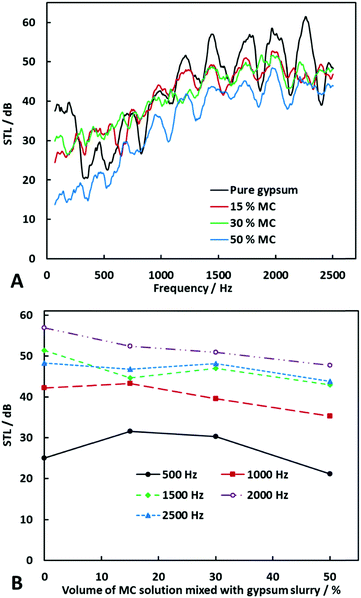
Fig. 5A shows the STL spectra of the porous gypsum composites produced using MC solution, along with the gypsum control sample whereas Fig. 5B shows the STL at specific sound frequencies as a function of the volume percentage of MC solution used during sample formulation. In general, the STL is lower for the porous gypsum composites than it is for the gypsum control sample with no added porosity. This is due to the surface density decreasing with increasing volume percentage of MC solution used during preparation, which allows more sound waves to propagate into and through the material. The reduction in reflected sound pressure due to this effect will therefore increase the transmitted sound pressure due to the law of conservation of energy:
| Ei = Er + Ea + Et. | (6) |
![[thin space (1/6-em)]](https://www.rsc.org/images/entities/char_2009.gif) :
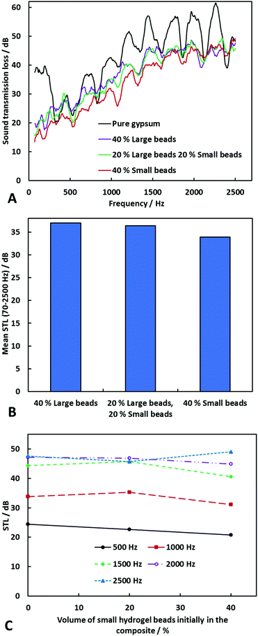
:![[thin space (1/6-em)]](https://www.rsc.org/images/entities/char_2009.gif) 1 volume ratio. Fig. 6A shows the results for the composites produced with either large or small pores. Note that the composite produced with 40% large hydrogel beads had a higher overall STL than the one produced with 40% small beads. This was more noticeable at lower frequencies and the difference between them decreased as the frequency increased. The difference between the two spectra was calculated as follows:
1 volume ratio. Fig. 6A shows the results for the composites produced with either large or small pores. Note that the composite produced with 40% large hydrogel beads had a higher overall STL than the one produced with 40% small beads. This was more noticeable at lower frequencies and the difference between them decreased as the frequency increased. The difference between the two spectra was calculated as follows:| ΔSTL = STLSB − STLLB. | (7) |
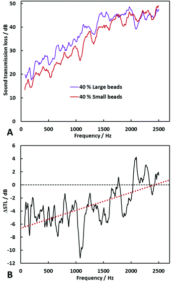 | ||
| Fig. 6 STL spectra of porous gypsum composites produced with 40% by volume of small or large beads (A) mixed with gypsum slurry followed by drying. (B) The difference between the STL spectra for composites produced with small beads and those with large beads was calculated as seen in eqn (7). The dotted red line is a best-linear-fit and the dashed black line shows the location of zero on the y-axis. | ||
We also tested the hierarchically porous composite produced with a combination of large and small hydrogel beads. It was seen that the STL spectrum lies between the spectra of the composites produced with only large beads and only small beads. This suggests possible tuning of sound insulating materials by varying the ratio of large to small pores in a material at constant overall porosity. The mean STL over the full frequency range was highest for the composites produced with large hydrogel beads and lowest for the ones produced with small beads, with the mixed size distribution of gel beads having an intermediate mean STL (see Fig. 7A and B). Fig. 7C shows how the STL at specific frequencies varies as the microstructure is varied. It can be seen that as the volume percentage of small beads in the overall volume percentage of hydrogel beads increases, the STL decreases at all frequencies apart from 2500 Hz, where it increases.
3.4. Mechanical properties
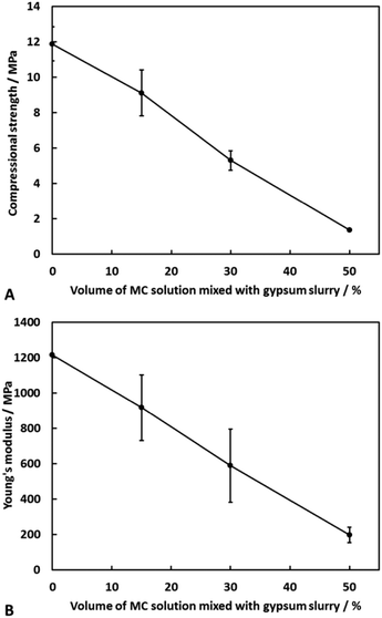
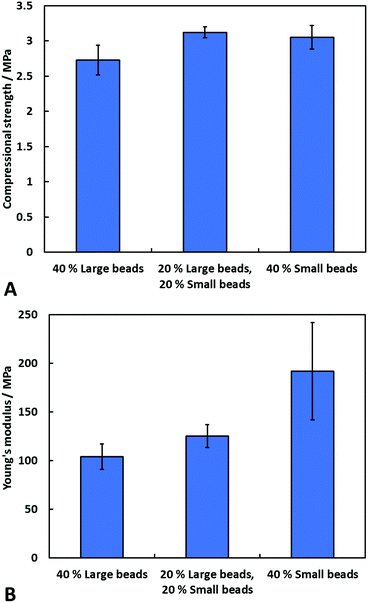
We have investigated the mechanical properties of the porous gypsum composites produced by the viscous trapping method using different volume percentages of MC solution. Fresh samples were prepared and dried to a constant mass. They were then subjected to compression until structural failure which allowed for calculation of the Young's modulus and the compressional strength, as shown in Fig. 8A and B. The mechanical properties of the porous and hierarchically porous gypsum composites produced with 40% by volume of hydrogel beads (small, large or a combination of the two) were also studied. The results are presented in Fig. 9A and B. A linear relationship between both the compressional strength and Young's modulus with the volume percentage of MC solution used during formulation (i.e. porosity) was seen. When the porosity was approximately 50%, the reduction in the compressional strength was 88% and the reduction in the Young's modulus was 84%.The average compressional strength and Young's modulus for the porous gypsum composites produced with large beads was 10% lower and 45% lower, respectively, than the ones produced with small beads alone. Other authors have also reported that materials with smaller pores have increased mechanical properties.9,28 The hierarchically porous sample has an intermediate Young's modulus, but a slightly higher compressional strength than either of the materials with pores on a single length scale. It has been suggested previously that hierarchically structured porous materials could, at certain ratios of large pores to small pores, produce materials with enhanced mechanical properties.29 This shows that it may be possible to tailor the mechanical properties of hierarchically porous gypsum composites by varying the ratio of large pores to small pores.
3.5. Microstructural analysis
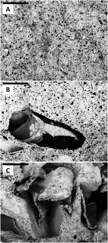
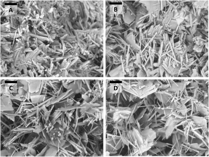
Specimens were taken from each porous sample and viewed without conductive coating with a benchtop SEM. The magnifications used were suitable for visualising the microstructural differences between each sample. Fig. 10A–C show the variation in microstructure for samples prepared by the hydrogel bead templating method using large beads, small beads, or a combination of the two. As seen in Fig. 10, the size of the pores reflects the size of the hydrogel bead templates used during the formulation process. Furthermore, one can see the residues left over in the pores by the dried hydrogel that made the large beads, whereas we do not observe these in the small pores, made by the small beads. This is likely due to the larger surface area to volume ratio of the small beads leading to thinner residues which will be prone to intercalating with the surrounding gypsum matrix. The residues left by the large hydrogel beads could increase the sound insulating properties, as it has been shown previously that the filler material that lines pores can significantly increase the STL.16Fig. 11A–C show the expansion of the innate porosity of gypsum samples prepared by using the viscous trapping method with MC solution. Through the use of the viscous MC solution, highly porous gypsum composites with an expanded particle network could be obtained. This expansion, however, lead to significant deterioration of the material mechanical properties as well as decreasing its sound insulation properties. The decrease in density of the material allows for easier transmission of sound waves through it, thereby decreasing the STL. Furthermore, we did not observe any dried MC residue within the porous composites at such resolution.
4. Conclusions
We have developed and utilised two different methods to produce hierarchically porous composites with simultaneous control over the overall porosity and the hierarchical microstructure: (i) a hydrogel bead templating technique was used to obtain hierarchically porous gypsum composites. Depending on the volume percentage of the hydrogel bead slurry and the size distribution of the beads, both the porosity and the pore size could be controlled. Materials of tuneable hierarchical porosity were produced by mixing slurries of large beads with small beads in controlled volume ratios, then using this “bimodal” slurry of beads as a porosity inducing template by further mixing with gypsum slurry followed by setting and drying. (ii) The second method involved viscous trapping of gypsum particles with MC solution which essentially dilutes the aqueous gypsum slurry but prevents its sedimentation due to gravity during the setting process. The viscosity of MC solution stops the sedimentation of the hydrated gypsum particles whilst the gypsum network forms, which leaves a porous gypsum composite with porosity expanded by a controlled amount, based on the volume percentage of MC solution.We studied the sound transmission loss (STL) of porous gypsum composites produced using these two methods. It was found that the porous composites formulated using MC solution had a decreased STL with increasing porosity, which can be explained by the interaction between the acoustic air flow and the frame of the porous material. This predicts that the STL decreases with increasing porosity of the sample, i.e. higher porosity has less resistance to the acoustic air flow. An investigation into how the pore size affected the STL of porous gypsum composites was performed. We obtained the STL spectra of porous gypsum composites produced by the hydrogel templating method with small beads or large beads at a constant porosity (40%). We found that at lower frequencies, the porous composites made with large beads have a higher STL. However, the difference between them decreases as the frequency increases. The data suggests that at frequencies above 2420 Hz, the porous composite produced with small hydrogel beads may have a higher STL, however this would need further testing. We also measured the STL spectra of the hierarchically porous gypsum composite with 40% porosity made by templating a mixed slurry of both large and small pores in a 1![[thin space (1/6-em)]](https://www.rsc.org/images/entities/char_2009.gif) :
:![[thin space (1/6-em)]](https://www.rsc.org/images/entities/char_2009.gif) 1 volume ratio. In this case the STL spectrum was in between the ones for the porous composites produced with only large or only small beads. This suggests there could be a possibility for tuning the STL of hierarchically porous materials at constant porosity through careful control of their microstructures.
1 volume ratio. In this case the STL spectrum was in between the ones for the porous composites produced with only large or only small beads. This suggests there could be a possibility for tuning the STL of hierarchically porous materials at constant porosity through careful control of their microstructures.
We also studied the mechanical properties of the porous gypsum composites. We found that there is a linear relationship between the overall porosity and the compressional strength or the Young's modulus for the porous composites produced using the viscous trapping method with MC solution. When using hydrogel beads to introduce porosity into the gypsum matrix, we found that small beads (and hence small pores) produced materials with increased mechanical properties. One possible explanation is that in the composites produced using large beads the dried hydrogel residue resides inside the pores and gypsum particles are attached to them. As they are not part of the continuous gypsum network, they do not contribute to the overall strength of the composite. Porous composites made with small beads get their hydrogel residue intercalated within the gypsum particle network which increases their overall compressional strength. The hierarchically porous gypsum composites showed an intermediate Young's modulus and an increased compressional strength.
Conflicts of interest
There are no conflicts to declare.Acknowledgements
B. R. T. acknowledges EPSRC Industrial CASE award and financial support from Unilever R&D Vlaardingen for his PhD studies.References
- W. Passchier-Vermeer and W. F. Passchier, Environ. Health Perspect., 2000, 108, 123–131 CrossRef PubMed.
- S. A. Stansfeld and M. P. Matheson, Br. Med. Bull., 2003, 68, 243–257 CrossRef PubMed.
- M. N. Mead, Environ. Health Perspect., 2007, 115, A536–A537 CrossRef PubMed.
- F. Godlee, Br. Med. J., 1992, 304, 110–113 CrossRef CAS PubMed.
- S. Ghaffari Mosanenzadeh, H. E. Naguib, C. B. Park and N. Atalla, J. Mater. Sci., 2015, 50, 1248–1256 CrossRef CAS.
- M. E. Delany and E. N. Bazley, Appl. Acoust., 1970, 3, 105–116 CrossRef.
- M. R. F. Kidner and C. H. Hansen, Int. J. Acoust. Vib., 2008, 13, 112–119 Search PubMed.
- M. Rutkevičius, G. H. Mehl, V. N. Paunov, Q. Qin, P. A. Rubini, S. D. Stoyanov and J. Petkov, J. Mater. Res., 2013, 28, 2409–2414 CrossRef.
- M. Rutkevičius, Z. Austin, B. Chalk, G. H. Mehl, Q. Qin, P. A. Rubini, S. D. Stoyanov and V. N. Paunov, J. Mater. Sci., 2015, 50, 3495–3503 CrossRef.
- J. Legault and N. Atalla, J. Sound Vib., 2009, 324, 712–732 CrossRef.
- C. M. Wu and M. H. Chou, Compos. Sci. Technol., 2016, 127, 127–133 CrossRef CAS.
- H. Meng, X. H. Yang, S. W. Ren, F. X. Xin and T. J. Lu, Compos. Sci. Technol., 2016, 127, 158–168 CrossRef.
- Z. Li and M. J. Crocker, J. Sound Vib., 2006, 294, 473–485 CrossRef.
- T. Han, X. Wang, Y. Xiong, J. Li, S. Guo and G. Chen, Composites, Part A, 2015, 78, 27–34 CrossRef CAS.
- J.-C. Lee, Y.-S. Hong, R.-G. Nan, M.-K. Jang, C. S. Lee, S.-H. Ahn and Y.-J. Kang, J. Mech. Sci. Technol., 2009, 22, 1468 CrossRef.
- L. Xu, T. Han, J. Li, Y. Xiong and S. Guo, Compos. Sci. Technol., 2017, 145, 78–88 CrossRef CAS.
- A. R. Barnard and M. D. Rao, presented in part at The 2004 National Conference on Noise Control Engineering, Baltimore, July, 2004.
- ASTM E2611-09, Standard Test Method for the Measurement of Normal Incidence Sound Transmission of Acoustical Materials Based on the Transfer Matrix Method, 2009, http://https://www.astm.org/Standards/E2611.htm (accessed 27/7/2017).
- M. Rutkevičius, S. K. Munusami, Z. Watson, A. D. Field, M. Salt, S. D. Stoyanov, J. Petkov, G. H. Mehl and V. N. Paunov, Mater. Res. Bull., 2012, 47, 980–986 CrossRef.
- M. Constantin, S.-M. Bucatariu, F. Doroftei and G. Fundueanu, Carbohydr. Polym., 2017, 157, 493–502 CrossRef CAS PubMed.
- L. Zhang, K. Li, W. Xiao, L. Zheng, Y. Xiao, H. Fan and X. Zhang, Carbohydr. Polym., 2011, 84, 118–125 CrossRef CAS.
- M. Rutkevičius, G. H. Mehl, J. T. Petkov, S. D. Stoyanov and V. N. Paunov, J. Mater. Chem. B, 2015, 3, 82–89 RSC.
- S. S. Jung, Y. T. Kim and Y. B. Lee, J. Korean Phys. Soc., 2008, 53, 596–600 CrossRef.
- P. S. Allan, A. Ahmadnia, R. Withnall and J. Silver, Polym. Test., 2012, 31, 312–321 CrossRef CAS.
- A. Hayashi and T. Kanzaki, Food Hydrocolloids, 1987, 1, 317–325 CrossRef CAS.
- A. J. Lewry and J. Williamson, J. Mater. Sci., 1994, 29, 5524–5528 CrossRef CAS.
- A. J. Lewry and J. Williamson, J. Mater. Sci., 1994, 29, 5279–5284 CrossRef CAS.
- Z. Li, L. Yang, Y. Li, Y. Yang, C. Zhou, Y. Ding, J. Zhao and Y. Li, Mater. Des., 2013, 45, 52–55 CrossRef CAS.
- L. L. C. Wong, P. M. Baiz Villafranca, A. Menner and A. Bismarck, Langmuir, 2013, 29, 5952–5961 CrossRef CAS PubMed.
- B. R. Thompson, T. S. Horozov, S. D. Stoyanov and V. N. Paunov, Food Funct., 2017, 8, 2967–2973 CAS.
- B. R. Thompson, T. S. Horozov, S. D. Stoyanov and V. N. Paunov, RSC Adv., 2017, 7, 45535–45544 RSC.
| This journal is © the Partner Organisations 2017 |

