Recyclable, bifunctional composites of perovskite type N-CaTiO3 and reduced graphene oxide as an efficient adsorptive photocatalyst for environmental remediation†
Ashish
Kumar
 ,
Suneel
Kumar
 ,
Ashish
Bahuguna
,
Ajay
Kumar
,
Ashish
Bahuguna
,
Ajay
Kumar
 ,
Vipul
Sharma
 and
Venkata
Krishnan
 *
*
School of Basic Sciences and Advanced Materials Research Center, Indian Institute of Technology Mandi, Kamand, Mandi 175005, Himachal Pradesh, India. E-mail: vkn@iitmandi.ac.in
First published on 6th September 2017
Abstract
Graphene–semiconductor photocatalysts are of utmost interest for achieving visible light activity but there is ambiguity about the role played by graphene in these photocatalysts. Such photocatalysts exhibit both adsorptive and photocatalytic activities towards pollutant degradation. Herein, we report nitrogen doped CaTiO3 (NCT) perovskite coupled with reduced graphene oxide (RGO), RGO–NCT, composites for the first time and utilize them for environmental remediation as an efficient adsorptive photocatalyst. The adsorption and photocatalytic activity were evaluated by investigating the adsorption/degradation of a model dye, methylene blue (MB). In comparison with bare CT and NCT, the RGO–NCT composites exhibit enhanced photocatalytic activity, which could be attributed to the synergistic effect of the adsorption of dye molecules on the RGO surface followed by their degradation under visible light irradiation. In the degradation mechanism, we propose that the degradation of MB is not only due to the dye photosensitization process but also involves the true photocatalytic action of the RGO–NCT composites. The clear role of graphene as an electron acceptor is demonstrated by photoluminescence spectroscopic study. Also, the degradation of a colorless pollutant thiabendazole (TBZ) under visible light irradiation supports our hypothesis. In addition, the commendable stability and recyclability of RGO–NCT photocatalysts demonstrates that these materials can be used as potential, viable and stable photocatalysts for environmental remediation. In principle, we anticipate that our work paves the way for tailoring the photocatalytic activity of perovskite-type semiconductor materials by coupling with graphene for the design of recyclable bifunctional photocatalysts.
1. Introduction
Environmental pollution is one of the major problems that the world is facing currently and it is increasing with every passing year due to the rapid industrial development and population growth, causing severe and irreparable damage to the earth. Particularly, water pollution is a major risk for human beings as well as for aquatic life.1 Solar energy driven photocatalysis is one of the attractive and promising strategies for alleviating these issues without consuming any additional energy and in a greener way. Semiconductor photocatalysis has drawn much attention of global researchers due to its potential towards degradation of organic pollutants in order to attain environmental sustainability.2,3 In this context, a variety of semiconductor systems including mixed metal oxides and their composites have been studied in the past few decades in the context of photocatalytic pollutant degradation.4 However, only limited literature reports are available on the use of perovskite based materials for photocatalytic applications, despite their highly favorable properties and huge potential.5 The perovskite compounds have a general chemical formula ABX3, where A and B are two cations of different sizes and X is an anion that bonds to the A and B cations. The two attractive strategies for enhancing the photocatalytic performance of these materials are band gap engineering and suppression of photogenerated charge carriers. The band gap of these materials can be tailored by doping A, B or X site elements and a suitable material, such as graphene, can be used as an electron transporter for suppressing the electron–hole recombination.4,5 Graphene is a two dimensional (2D) sheet of sp2 bonded carbon atoms having a honeycomb-like lattice structure. The excellent properties of graphene such as high transparency, flexible structure, electronic properties, large specific surface area and tunability of surface properties via chemical modifications facilitate its use in composite materials. Graphene based composites offer promising adsorptivity, conductivity, transparency and controllability, which improve their photocatalytic performance.6–8Calcium titanate (CaTiO3) is a widely abundant and a well-known perovskite material with a band gap of 3.5 eV and its photocatalytic activity is limited to UV light only.9,10 Interestingly, in CaTiO3 (CT), the conduction band minimum (CBM) lies at much higher negative potential in comparison with the well explored TiO2.11 This highly negative CBM of titanates can be utilized for achieving high photocatalytic activity towards pollutant degradation as well as for photocatalytic hydrogen generation. The large band gap of CT restricts its viability as a visible light active photocatalyst. Also the quantum efficiency of CT is curtailed by rapid recombination of photo-induced charge carriers, which is another dreadful concern. This problem is common in most of the semiconductor materials and to overcome this problem, various studies have been carried out in which RGO based support materials are used to enhance the activity of the photocatalysts by quenching the electron–hole recombination.12,13 Moreover, the role of an ideal support is to provide a large surface area, open pores for fast mass transport and sufficient surface sites for supporting the catalyst.14 Thus, graphene based semiconductor photocatalysts are of great interest and have continued to be explored in the recent times to achieve high photocatalytic activity.15,16 Bajorowicz et al. synthesized novel RGO–KTaO3 composites with highly improved photocatalytic performance for the degradation of phenol under visible light and attributed this to the formation of p–n heterojunctions between KTaO3 and RGO sheets as well as to the photosensitization by graphene.17 Zhang et al. demonstrated the visible light activity of P25–graphene composites for the degradation of MB caused by the adsorption of MB and charge transportation on two dimensional (2D) graphene.6 Furthermore, various attempts have been made by researchers to enhance the photocatalytic activity of CT, in this regard, Xian and colleagues fabricated Ag-decorated CT nanoparticles with enhanced photocatalytic activity for the degradation of MO under UV light.18 In another study, they reported a CT–graphene composite with enhanced photocatalytic activity for MO degradation under UV light.19 CT with different morphologies has also been reported with enhanced photocatalytic activity for pollutant degradation.20,21 However, there are only a few reports on visible light active CT based photocatalysts. Wang et al. reported fern-like Ag/AgCl/CT plasmonic photocatalysts with enhanced visible-light photocatalytic activity towards the degradation of MB, MO and RhB.22 Also, by doping various transition elements and lanthanides and coupling noble metals with CT, researchers have demonstrated visible light photocatalytic activity for hydrogen evolution from water.23–26 Nitrogen doping is another approach, which is well reported in the literature to achieve visible light photocatalytic activity in other perovskite materials.27–29 However, there are no such reports in the case of CT to the best of our knowledge.
The conventional adsorption of pollutants by activated charcoal, silica gel, MOFs etc. requires rigorous conditions for desorption and their recycling process is non-green and expensive.30 Thus, it is enviable to develop materials which can merge adsorption with photocatalysis resulting in the formation of efficient bifunctional adsorptive photocatalysts. In our work, we have designed and prepared a nitrogen doped CaTiO3 (NCT) coupled with reduced graphene oxide, RGO–NCT, composite for the first time and demonstrated it as a bifunctional adsorptive photocatalyst. Three crucial properties, i.e. adsorption of pollutant molecules, light absorption and charge transportation and separation are blended in a single material to obtain an efficient adsorptive photocatalyst. These composites offer excellent adsorptivity and photocatalytically degrade the adsorbed pollutants under visible light irradiation. In addition, the regeneration of the adsorptive photocatalyst is also fast and an environmentally benign solution could be achieved for the complete removal of detrimental pollutants. Thus, the as prepared composites manifest excellent visible light driven photocatalytic performance for the degradation of organic pollutants of wastewater, methylene blue (MB) and thiabendazole (TBZ). The commendable stability and recyclability of the RGO–NCT photocatalyst support our hypothesis that this system can be designated as a potential, viable and stable photocatalyst in the photocatalysis domain for environmental sustainability. Therefore, we anticipate that our results will pave the way to the design of visible light functional and reusable adsorptive perovskite based photocatalysts.
2. Experimental section
2.1. Materials
Titanium diisopropoxide bis(acetylacetonate) was purchased from Sigma Aldrich, India and used as received. Calcium chloride (CaCl2anhyd.) was supplied by SDFCL, India and ethanol from Fisher chemicals, India with assay >99.99%. Graphite powder (crystalline, 300 mesh, 99%) was purchased from Alfa Aesar, India. Ammonia solution (NH3 about 25%), sodium nitrate (NaNO3), sulfuric acid (H2SO4), potassium permanganate (KMnO4) and hydrogen peroxide (H2O2) were supplied by Merck, India and used as received. Deionized water obtained from a double stage water purifier (ELGA PURELAB Option-R7) was used for all experimental work.2.2. Synthesis and characterization
![[thin space (1/6-em)]](https://www.rsc.org/images/entities/char_2009.gif) :
:![[thin space (1/6-em)]](https://www.rsc.org/images/entities/char_2009.gif) 2 ratio. A subsequent amount of NCT was added to it and the resulting mixture was stirred for about 2 hours to obtain a homogeneous suspension. The final mixture was transferred into a Teflon lined autoclave and maintained at 150 °C for 10 hours and allowed to cool naturally. Thus the obtained product was centrifuged and washed several times with distilled water and dried at 60 °C under vacuum. In this work, a series of RGO–NCT composites is prepared with varying GO contents of 1, 3, 5, 10 and 20 wt% with respect to the NCT amount and the corresponding samples have been marked as NCTG01, NCTG03, NCTG05, NCTG10 and NCTG20, respectively.
2 ratio. A subsequent amount of NCT was added to it and the resulting mixture was stirred for about 2 hours to obtain a homogeneous suspension. The final mixture was transferred into a Teflon lined autoclave and maintained at 150 °C for 10 hours and allowed to cool naturally. Thus the obtained product was centrifuged and washed several times with distilled water and dried at 60 °C under vacuum. In this work, a series of RGO–NCT composites is prepared with varying GO contents of 1, 3, 5, 10 and 20 wt% with respect to the NCT amount and the corresponding samples have been marked as NCTG01, NCTG03, NCTG05, NCTG10 and NCTG20, respectively.
![[thin space (1/6-em)]](https://www.rsc.org/images/entities/char_2009.gif) min−1 with a flow rate of 20 mL
min−1 with a flow rate of 20 mL![[thin space (1/6-em)]](https://www.rsc.org/images/entities/char_2009.gif) min−1 in all experiments. Energy dispersive X-ray spectroscopy (EDAX) and morphological investigations were performed using a scanning electron microscope (SEM), FEI Nova Nano SEM-450, and a transmission electron microscope (TEM), an FEI Tecnai G2 20 S-twin microscope operating at 200 kV. Elemental mapping was also carried out using the same TEM instrument. X-ray photoelectron spectroscopic (XPS) analysis was carried out on a PREVAC photoemission spectrometer having an Al Kα (1486.6 eV) dual anode as the source, operating at a 12 kV anode voltage and 23 mA filament current. The XPS data were collected with a pass energy of 50 eV at 6.1 × 10⁻¹⁰ mbar vacuum using a Scienta R3000 electron energy analyzer. Optical properties were determined by UV-vis diffuse reflectance spectroscopy (DRS) with a Perkin Elmer UV-vis-NIR Lambda 750 spectrophotometer by taking the polytetrafluoroethylene (PTFE) polymer as a standard. The photocatalytic studies were performed using a homemade photoreactor setup consisting of two 14 W white light emitting LED lamps, which together produce an intensity of approximately 55
min−1 in all experiments. Energy dispersive X-ray spectroscopy (EDAX) and morphological investigations were performed using a scanning electron microscope (SEM), FEI Nova Nano SEM-450, and a transmission electron microscope (TEM), an FEI Tecnai G2 20 S-twin microscope operating at 200 kV. Elemental mapping was also carried out using the same TEM instrument. X-ray photoelectron spectroscopic (XPS) analysis was carried out on a PREVAC photoemission spectrometer having an Al Kα (1486.6 eV) dual anode as the source, operating at a 12 kV anode voltage and 23 mA filament current. The XPS data were collected with a pass energy of 50 eV at 6.1 × 10⁻¹⁰ mbar vacuum using a Scienta R3000 electron energy analyzer. Optical properties were determined by UV-vis diffuse reflectance spectroscopy (DRS) with a Perkin Elmer UV-vis-NIR Lambda 750 spectrophotometer by taking the polytetrafluoroethylene (PTFE) polymer as a standard. The photocatalytic studies were performed using a homemade photoreactor setup consisting of two 14 W white light emitting LED lamps, which together produce an intensity of approximately 55![[thin space (1/6-em)]](https://www.rsc.org/images/entities/char_2009.gif) 000 lux, measured using an LX-101A digital luxmeter. The time-dependent UV-visible absorption spectra of the samples were recorded using a Shimadzu UV-2450 spectrophotometer in the wavelength range from 200 nm to 800 nm. All the photoluminescence (PL) spectra were recorded on an Agilent Technologies Cary Eclipse fluorescence spectrophotometer. The intermediates generated during the photocatalytic degradation of MB were analyzed by using a Bruker HD compact mass spectrometer instrument.
000 lux, measured using an LX-101A digital luxmeter. The time-dependent UV-visible absorption spectra of the samples were recorded using a Shimadzu UV-2450 spectrophotometer in the wavelength range from 200 nm to 800 nm. All the photoluminescence (PL) spectra were recorded on an Agilent Technologies Cary Eclipse fluorescence spectrophotometer. The intermediates generated during the photocatalytic degradation of MB were analyzed by using a Bruker HD compact mass spectrometer instrument.
| DRMB = (1 − Ct/C0) × 100 |
The adsorption phenomenon was studied for the best composition NCTG20 and the concentration of MB was varied from 1 × 10⁻⁵ M to 15 × 10−5 M. Each experiment was performed by mixing 50 mg of the above mentioned photocatalyst and 50 mL of dye solution. These mixtures were stirred in the dark for 1 hour to attain adsorption–desorption equilibrium between MB molecules and the adsorbent. The equilibrium concentration (Ce) of MB was calculated using a UV-visible spectrophotometer. The adsorption capacity, qe (mg g−1) is given by the following equation:34
| qe = (C0 − Ce) × W/V |
3. Results and discussion
3.1. Crystal structure analysis
The X-ray diffraction (XRD) measurements were performed on GO, RGO, CT, NCT and various RGO–NCT composites to identify their crystal planes and the corresponding data are presented in Fig. 1a. GO exhibits a diffraction peak around 2θ = 10.3° which corresponds to the oxidation of graphite powder into GO. The disappearance of this GO peak confirms its complete reduction into RGO which exhibits a diffraction peak at 2θ = 24.7° as shown in Fig. S1 in the ESI.†![[thin space (1/6-em)]](https://www.rsc.org/images/entities/char_2009.gif) 35 The diffraction peaks of pristine CT are well indexed to the orthorhombic phase (JCPDS card no. 42-0423, a = 5.442 Å, b = 7.642 Å, c = 5.381 Å) with good crystallinity.21 The absence of other peaks ensures the high purity and single phase orthorhombic CaTiO3. For NCT (Fig. 1b), all diffraction peaks are similar to that of pristine CT but a small shift in the (121) face of NCT peaks is observed, which indicates the substitution of O2− sites with N3− ions as the ionic radius value of the N3− ion is higher than that of the O2− ion (0.171 nm and 0.140 nm, respectively). It is worth mentioning here that, the peak for N3− is not observed in the spectra, which can be attributed to the low concentration of nitrogen incorporated into the crystal lattice of CaTiO3.33 The incorporation of nitrogen into the crystal lattice of CaTiO3 results in some internal strain which is responsible for this shift as reported in the literature.36 It can be seen that the diffraction peak of GO disappears in RGO–NCT composites due to the conversion of GO into RGO. Since the amount of RGO in the composites is not very high it leads to a relatively weak diffraction intensity and therefore the diffraction peaks for RGO are not observed prominently in the RGO–NCT composites. Also, RGO–NCT composites having different weight percentages of RGO showed XRD patterns similar to that of NCT indicating that the crystal structures remain intact in all final composites.19,37,38
35 The diffraction peaks of pristine CT are well indexed to the orthorhombic phase (JCPDS card no. 42-0423, a = 5.442 Å, b = 7.642 Å, c = 5.381 Å) with good crystallinity.21 The absence of other peaks ensures the high purity and single phase orthorhombic CaTiO3. For NCT (Fig. 1b), all diffraction peaks are similar to that of pristine CT but a small shift in the (121) face of NCT peaks is observed, which indicates the substitution of O2− sites with N3− ions as the ionic radius value of the N3− ion is higher than that of the O2− ion (0.171 nm and 0.140 nm, respectively). It is worth mentioning here that, the peak for N3− is not observed in the spectra, which can be attributed to the low concentration of nitrogen incorporated into the crystal lattice of CaTiO3.33 The incorporation of nitrogen into the crystal lattice of CaTiO3 results in some internal strain which is responsible for this shift as reported in the literature.36 It can be seen that the diffraction peak of GO disappears in RGO–NCT composites due to the conversion of GO into RGO. Since the amount of RGO in the composites is not very high it leads to a relatively weak diffraction intensity and therefore the diffraction peaks for RGO are not observed prominently in the RGO–NCT composites. Also, RGO–NCT composites having different weight percentages of RGO showed XRD patterns similar to that of NCT indicating that the crystal structures remain intact in all final composites.19,37,38
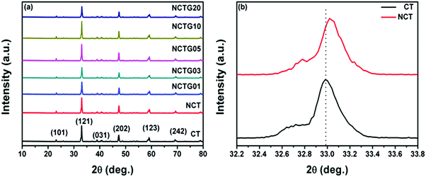 | ||
| Fig. 1 (a) XRD pattern of CT, NCT and RGO–NCT composites with varying RGO contents, and (b) the Bragg angle shift of the (121) diffraction peak in NCT as compared to CT. | ||
Raman spectroscopy measurements were performed to identify the crystal defects and lattice disorders in all prepared photocatalysts. It can be clearly seen in Fig. 2a that the Raman spectrum of pristine CT bricks shows eight intense peaks at 180 cm−1, 227 cm−1, 247 cm−1, 285 cm−1, 339 cm−1, 468 cm−1, 537 cm−1 and 641 cm−1, which can be assigned to the orthorhombic phase in accordance with the previous reports.22,39 A Raman band at 180 cm−1 arises due to the motion of A-site (Ca2+) ions. The bands in the region 227–339 cm−1 could be assigned to the O–Ti–O bending vibration modes and the band at 468 cm−1 is associated with the Ti–O torsional modes (bending or internal vibration of oxygen cage). In addition, the Raman band at 641 cm−1 can be assigned to the Ti–O symmetric stretching vibrations.39,40 In the case of NCT, peaks similar to CT could be evidenced, but with a decreased intensity and significant broadening. This broadening of the peaks might be due to the disturbance in the crystal lattice of pure CT due to nitrogen incorporation.
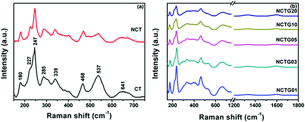 | ||
| Fig. 2 (a) Raman spectra of CT and NCT and (b) Raman spectra of RGO–NCT composites with varying RGO contents. | ||
It is important to mention here about the reduction of GO to RGO during the hydrothermal synthesis process. GO is reduced to RGO by a similar method explained for the synthesis of RGO–NCT composites. The Raman spectra of GO and RGO is shown in Fig. S2 (ESI†). The Raman spectra of GO exhibit two prominent peaks at around 1340 cm−1 and 1590 cm−1 corresponding to D and G bands, which arise due to the sp3 hybridized carbon and E2g phonon mode of the crystalline graphite.41 It is clear from Fig. S2 (ESI†) that the intensity ratio of the D to G band (ID/IG) for GO is 0.89 and for RGO it is significantly enhanced to 1.18. This points towards the successful reduction of GO to RGO and structural alterations to reduce the defects.42 The Raman spectra of the as prepared RGO–NCT composites exhibit (Fig. 2b) all the characteristic peaks corresponding to NCT and RGO; a decrease in the intensity of the peaks with an increase in the RGO content confirms the intimate contact between both.
3.2. Thermogravimetric analysis (TGA)
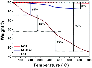
Thermogravimetric analysis (TGA) of CT, NCT, GO and a representative photocatalyst, the NCTG20 composite, has been carried out in order to determine their stability. The experiments were performed under nitrogen atmosphere and the corresponding TGA curves are depicted in Fig. 3. GO being thermally unstable shows about 14% weight loss below 200 °C which could be attributed to the loss of the adsorbed water molecules from the interlayers of GO. Further weight loss from 200 °C to 440 °C (18%) arises from the decomposition of oxygen containing functional groups attached to the GO layers. Upon further heating, decomposition of the carbon skeleton takes place (23%).17,43 Furthermore, NCT is highly stable up to 800 °C as the mass loss in its case is negligible, which can be attributed to the release of oxygen at high temperature.44 Also, the NCTG20 composite shows higher thermal stability compared to GO and shows only 8% mass loss. The greater mass loss in the case of GO is due to the presence of oxygen functionalities. These functionalities undergo reduction during the conversion of GO into RGO and hence the NCTG20 composite shows the main mass loss at higher temperatures corresponding to the thermal decomposition of the carbon skeleton only. This reflects the high thermal stability of RGO–NCT composites.3.3. Morphological and compositional analysis
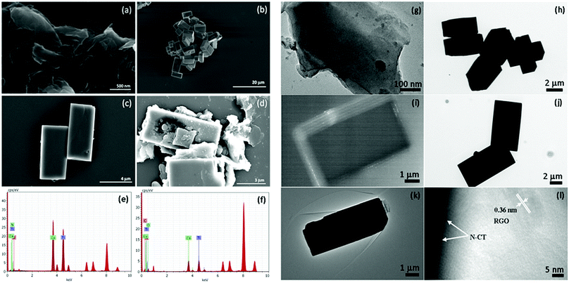
The microscopic morphologies of GO, CT, NCT and NCTG20, as representative samples are studied by using a field emission scanning electron microscope (FESEM) and the obtained images are presented in Fig. 4. Fig. 4a shows the sheet-like morphology of GO, while Fig. 4b and c reveal the brick-like morphology of the CT and NCT materials. The bricks are uniform with an average length of 6 ± 2 μm and width of 3 ± 2 μm. Fig. 4d shows good blending of RGO sheets with NCT bricks to form a composite. The elemental composition of NCT (Fig. 4e) and NCTG20 (Fig. 4f) is determined by EDAX spectroscopy, which confirms the presence of all the constituent elements.Furthermore, transmission electron microscopy measurements were performed on the same materials to gain more insight into their morphology. Fig. 4g shows the sheet-like morphology of GO. Low magnification TEM images of CT and NCT are shown in Fig. 4h and j, respectively and the dark field image in Fig. 4i confirms the layered structure of the perovskite-like CT.45Fig. 4k and l confirm the coupling of NCT bricks with wrinkled sheet-like RGO. The high resolution image of the NCTG20 composite shows fringes with an interlayer distance of 0.36 nm along with the edge of the NCT brick.46
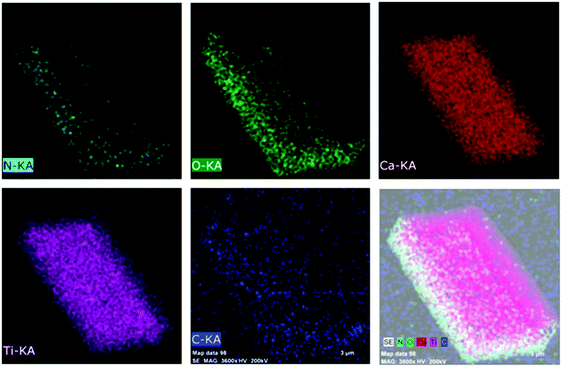
The extent of distribution of elements in CT, NCT and NCTG20 composites was determined by elemental mapping studies. The results of the elemental mapping studies (Fig. 5) of the NCTG20 composite confirms the coexistence of C, N, O, Ca, and Ti elements. In NCTG20, the mapping distribution of C displays a larger region out of the boundaries of the NCT bricks confirming the presence of RGO layers which complement the TEM results i.e., NCT bricks are supported on RGO nanosheets. Furthermore, the distribution of all the elements in the pristine CT and NCT bricks is homogeneous and shows the successful doping of nitrogen in pristine CT (Fig. S3 and S4 in the ESI†).
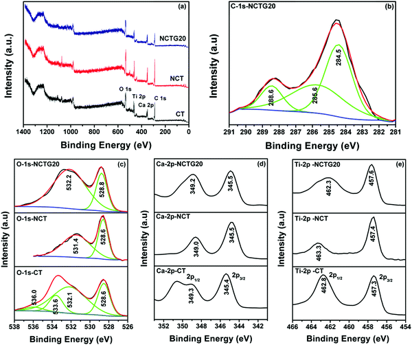
The XPS measurements on the CT, NCT and NCTG20 samples were carried out in order to understand the alteration in the electronic environment of the systems as a result of the N-doping and RGO coupling. It is important to note that XPS analysis provides information about the elements present only on the surface and does not look into the bulk of the material. The survey spectrum for the above mentioned samples is depicted in Fig. 6a. Fig. 6b shows the peaks for C-1s of the NCTG20 composite, there is a definite peak of sp2 hybridized carbon corresponding to the binding energy value (BE) 285.6 eV, which represents the RGO in the NCTG20 sample.32 Spectra corresponding to O-1s for the different samples are portrayed in Fig. 6c. The O-1s of CT has four different peaks at the BE values of 528.6 eV, 532.1 eV, 533.6 eV and 536.0 eV respectively. The peak at 528.6 eV represents the oxygen present in the lattice structure of CT, that at 532.1 eV represents the O2− defects present on the surface of CT, that at 533.6 eV could be assigned to the surface –OH groups and that at 536.0 eV represents oxygen vacancies.47–50 In the case of NCT and NCTG20, a significant shift in the peaks is observed, which can be attributed to the N-doping and incorporation of RGO. Fig. 6d shows the BE values related to the Ca-2p peaks for different samples. Herein, we observed that the peak for Ca-2p3/2 is obtained at 345.4 eV and the peak at 349.3 eV arises from the 2p1/2 orbital of Ca, which is consistent with the previous literature.47 Upon N-doping, there is not much alteration in the electronic environment of Ca and the same is the case upon coupling of NCT with RGO. Therefore, we can possibly comment that there is no electronic interaction with the Ca part of CT upon N-doping and with dispersion over RGO. The small shift in the BE value of the Ca could be considered within the limits of error. The other Ti-2p is depicted in Fig. 6e, where we can find the peaks for Ti-2p3/2 for the CT sample at 457.3 eV and that of 2p1/2 at 462.8 eV, which is in accordance with the earlier literature.47,51 Upon N-doping or even with the NCTG20 composite, there is very small alteration in the Ti-2p peaks. The elemental detection by XPS (not shown here) does not show the presence of N in the NCT and NCTG20 composite. This is mostly due to the fact that N may not be present on the surface to that extent as it is present in the bulk. However, the presence of C could definitely be identified for the NCTG20 sample.
3.4. Optical properties studies
The optical properties of all the prepared samples were investigated by UV-visible diffuse reflectance spectroscopy (DRS) in the range of 200–800 nm and the obtained data are shown in Fig. 7. Plots obtained by the transformation based on the Kubelka–Munk function vs. energy of light are presented in Fig. S5 in the ESI.† Optical absorption is directly related to the electronic band gap structure of a particular material and determines the photocatalytic activity of that material. From Fig. 7 it is clear that pristine CT exhibits an absorption edge at around 360 nm, which corresponds to the band gap energy of 3.5 eV and there is no absorption in the visible region (λ > 400 nm). N substitution significantly affects the electronic structure of CT as its absorption edge shifts to around 365 nm, corresponding to the band gap energy of 3.47 eV and a small absorption beyond 400 nm can also be seen. This decrease in the band gap leads to the formation of additional energy levels induced by N-doping on top of the valence band (VB) of CT and shifts its absorption towards the visible region. Compared to CT, NCT shows a red shift in the absorption wavelength (Fig. 7), which supports the successful incorporation of N into the CT lattice. Furthermore, the absorption in the visible region is enhanced for the RGO–NCT composites as compared to the pristine CT and NCT. It is worth mentioning here that the absorption in the visible region increases with the incorporation of more amount of RGO into the composites. This is consistent with the fact that the addition of graphene enhances the visible light absorption and thus improves the photocatalytic activity of the materials under visible light irradiation.17 Therefore, DRS data clearly show that the synergetic effect of N-doping and RGO support in CT bricks is responsible for the enhanced absorption of visible light by the composites.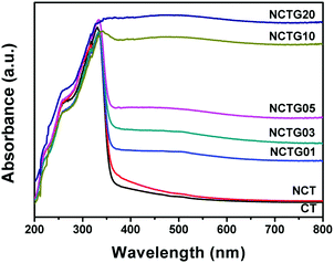 | ||
| Fig. 7 UV-visible diffuse reflectance spectra (DRS) of CT, NCT and RGO–NCT composites with varying RGO contents. | ||
3.5. Photocatalytic activity studies
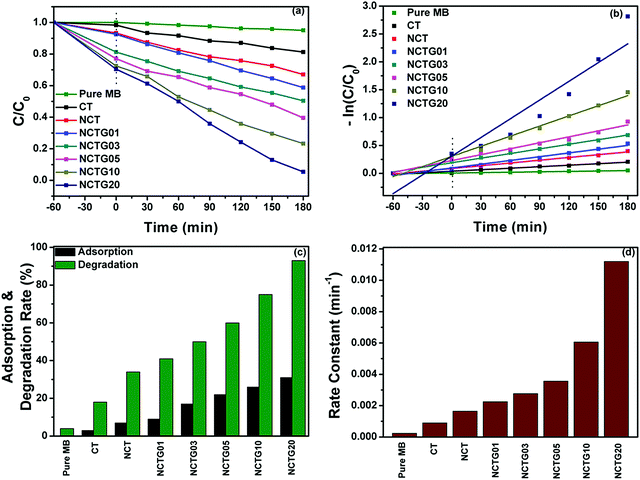
The photocatalytic degradation studies were performed by taking the MB dye as a model pollutant under visible light irradiation. For this, the characteristic absorption peak of MB at 664 nm (4 × 10⁻⁵ M) initial concentration, 50 mL aqueous solution was monitored with a UV-visible spectrophotometer after regular intervals of time (30 min). The time dependent absorption spectra of bare MB solution and absorption spectra of MB in the presence of CT, NCT and various RGO–NCT composites are provided in Fig. S6 (ESI†). The photodegradation of the bare MB solution shows very small degradation signifying its high photostability under visible light.The initial decrease in the absorbance of MB solution enhances with the increase in the RGO content, which could be attributed to the enhanced adsorption during stirring in the dark for 60 min. Furthermore, the absorbance decrease under visible light irradiation is due to the degradation of MB. The kinetic curves pertaining to the photocatalytic degradation of MB using different catalysts are shown in Fig. 8a and b. The individual adsorption percentage and total degradation percentage are shown in the histogram (Fig. 8c). It can be seen from the degradation plots that the degradation of MB observed in the presence of CT was less compared to NCT. Furthermore, the degradation percentage was increased as the RGO content increased in the RGO–NCT composites and about 95% degradation was observed in the case of the NCTG20 composite. The degradation rates (%) calculated for CT, NCT, NCTG01, NCTG03, NCTG05, NCTG10 and NCTG20 were 18%, 34%, 41%, 50%, 60%, 75% and 95%, respectively, for 180 min of visible light irradiation. These results show that the incorporation of RGO in high wt% enhances the photocatalytic activity from 41% to 95%.
Graphene is known for effectively suppressing the electron–hole pair recombination and can act as a photosensitizer to enhance the harvesting of visible light in the photocatalysis process. Also, the unique 2D structure with an exceptionally high surface of graphene provides support to the NCT bricks, which can offer more active photocatalytic sites. In the present study, we restricted the amount of RGO to 20 wt% in the final composite as higher graphene amounts can cause a decrease in the light absorption and hence results in a decrease in the performance of the working photocatalyst.52
The photocatalytic degradation kinetics was investigated by applying pseudo-first-order kinetics as per the Langmuir–Hinshelwood model:
ln![[thin space (1/6-em)]](https://www.rsc.org/images/entities/char_2009.gif) C/C0 = −kt C/C0 = −kt |
To confirm that MB is not only undergoing photosensitization but photocatalyst also has true activity, we also studied the photocatalytic degradation of a well-known plant fungicide, thiabendazole (TBZ), a colorless pollutant, under identical conditions. TBZ is widely used in the protection and production of citrus fruits and is carcinogenic in nature beyond certain limits.10 The photocatalytic degradation of TBZ is demonstrated by monitoring its UV-visible spectral behavior (Fig. S7 in ESI†) at an absorption maximum of 298 nm (2 × 10⁻⁵ M initial concentration). In control experiments, TBZ is found to be highly stable under visible light irradiation. NCT shows more photocatalytic activity in comparison with pristine CT similar to the degradation results obtained for the MB dye. However, the adsorption of TBZ over both CT and NCT is negligible. With the NCTG20 composite, the adsorption of TBZ enhances drastically (about 50%) which can be attributed to the graphene content present in the catalyst. About 90% degradation of TBZ is observed with the NCTG20 composite reflecting its high photocatalytic activity under visible light irradiation. A persuasive explanation of this observation is that the RGO–NCT composites have good photocatalytic activity under visible light as proposed in the case of photodegradation of an aqueous solution of MB. However, the process of degradation of TBZ may not be similar to that of MB due to the structural difference between TBZ and MB.
3.6. Effect of MB concentration on degradation of MB solution
To determine the most favorable concentration of MB for its degradation over NCTG20 under visible light, degradation experiments were carried out by varying the concentration of MB (1–5 × 10⁻⁵ M) with a fixed amount of photocatalyst (50 mg). Fig. S8 (refer ESI†) shows that with increase in the concentration of MB solution from 1 × 10⁻⁵ M to 5 × 10⁻⁵ M, the degradation time increases and reaches 180 minutes, up to which more than 90% degradation is observed. However, further increase in MB concentration results in a decline in the degradation rate. For 5 × 10⁻⁵ M MB solution, only 67% degradation is observed within 180 minutes and we continued the experiment up to 270 minutes and recorded 83% degradation. This decrease in the photocatalytic activity is attributed to the fact that the absorption of light by the dye molecules is more than that of the active photocatalyst and the light absorbed by MB cannot trigger the degradation reaction. Also, the blocking of the surface of the photocatalyst with an increase in MB concentration reduces the active sites for the generation of charge carriers and consequently decreases the photocatalytic performance.53 Thus, MB solution with 4 × 10⁻⁵ M initial concentration was found to be most appropriate to obtain the best photocatalytic performance with the designed composite.3.7. Adsorption study of MB from aqueous solution
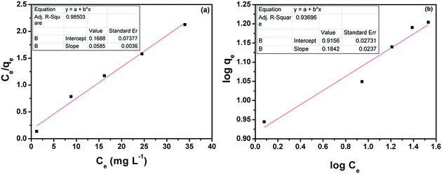
It is well known that RGO has a strong tendency to adsorb pollutants because of its large surface area.54,55 The adsorption of MB molecules on the 2D graphene surface is governed by non-covalent π–π interactions between the aromatic regions of both.6 The NCTG20 composite with the maximum content of RGO can act as a promising adsorbent. The adsorption activity of NCTG20 is demonstrated by performing adsorption/degradation experiments with varying concentrations of MB. It can be seen from Fig. S8(f) in the ESI† that with increase in the concentration of MB, the amount of MB adsorbed per unit weight of adsorbent (qe) also increases. This enhanced adsorption can be attributed to the high adsorption capacity of RGO incorporated into the working catalyst and more MB molecules get adsorbed on the surface of the adsorbent to overcome all mass transfer resistances with an increase in dye concentration.34The experimental equilibrium adsorption of MB on NCTG20 was also interpreted by fitting the equilibrium adsorption data using the Langmuir and Freundlich adsorption isotherm equations:34
| Ce/qe = 1/KLqm + Ce/qm (Langmuir adsorption isotherm) |
log![[thin space (1/6-em)]](https://www.rsc.org/images/entities/char_2009.gif) qe = log qe = log![[thin space (1/6-em)]](https://www.rsc.org/images/entities/char_2009.gif) KF + log KF + log![[thin space (1/6-em)]](https://www.rsc.org/images/entities/char_2009.gif) Ce/n (Freundlich adsorption isotherm) Ce/n (Freundlich adsorption isotherm) |
The adsorption capacity qe (mg g−1) of the catalyst was calculated by dispersing the catalyst in various concentrations of MB for a fixed period of time (60 min). The corresponding Langmuir and Freundlich isotherms are shown in Fig. 9(a) and (b). The maximum adsorption capacity qm is determined by fitting the adsorption equilibrium data to the Langmuir model as shown in Fig. S8(f) in the ESI.† With an increase in the MB concentration, qe also increases up to a maximum experimental value of qm equal to 16 mg g−1, which is slightly less than the theoretical qm value. This adsorption capacity is not very high compared to that of similar adsorptive photocatalysts,56,57 but the photocatalytic activity of NCT has the benefit of degrading the adsorbed dye under visible light and recovering the adsorption properties of NCTG20. To support these claims, we performed the Raman spectroscopic measurements of the fresh and recycled NCTG20 composite and the absence of MB Raman peaks in the recycled photocatalyst confirms our hypothesis (Fig. S9 in the ESI†). The correlation coefficient value for both adsorption isotherms is provided in Table S2 in the ESI.† The adsorption data of the NCTG20 composite fitted with the Langmuir model were better compared to the Freundlich model.
3.8. The intermediates of MB degradation
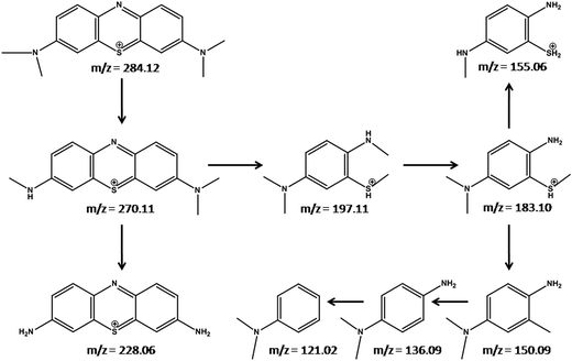
To analyze the degradation intermediates of MB under visible light irradiation over the NCTG20 composite, mass spectrometric analysis was performed. Mass spectra of degraded MB solutions collected at different time intervals were recorded and the corresponding spectra are presented in Fig. S10 (ESI†). These were analyzed to predict the intermediates formed during the photocatalytic degradation process. A major peak at m/z = 284.12 corresponds to MB dye molecules. The peaks at m/z = 270.11 and 228.06 correspond to Azure B and thionine, which are the resulting products of demethylation processes.58 Furthermore, cleavage of the MB molecule gives small organic degraded products corresponding to the mass values, m/z = 197.11, 183.10, 155.06, 150.09, 136.09 and 121.02. Based on these results, we proposed a plausible mechanism for the photocatalytic degradation of MB as depicted in Fig. 10.3.9. Photoluminescence studies
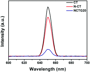
In order to understand the effect of RGO loading in RGO–NCT composites on photogenerated electron–hole separation, photoluminescence (PL) studies were performed and the obtained PL spectra of the photocatalysts are displayed in Fig. 11. The behavior of photogenerated free charge carriers in semiconductor materials can be effectively studied using the PL emission spectra, since PL emission intensity results from the recombination of photogenerated excited electrons and holes.59,60 The PL spectra of pristine CT, NCT and NCTG20 were recorded at room temperature in the wavelength range of 600–700 nm with an excitation wavelength at 360 nm corresponding to the band gap of 3.5 eV. Pristine CT gives the highest PL emission at around 650 nm, which arises due to the high rate of electron–hole recombination and hence shows the lowest photocatalytic activity.61 The intensity of the PL peak of the NCT shows a significant decrease as compared to pristine CT, which indicates that the recombination rate of photogenerated charge carriers is suppressed and their transfer to the reaction sites is enhanced by N-doping.33 Furthermore, the PL intensity for the NCTG20 composite is notably the lowest compared to that of pristine CT and NCT suggesting effective suppression of photogenerated charge carriers with the loading of RGO in the bare NCT. Thus, efficient separation of electron–hole pairs is advantageous for enhancing the photocatalytic performance of RGO–NCT composites and provides a large number of free charge carriers for the desired photocatalytic reaction.173.10. Photocatalyst reusability
Reusability is a crucial factor for a photocatalyst which reflects its superiority in the photocatalysis domain. The intimate contact between RGO sheets and NCT bricks is the key factor influencing the stability and thereby, recyclability of RGO–NCT composites. The reusability of NCTG20, a representative photocatalyst was investigated by performing three adsorption/degradation cycles for a period of 180 min under visible light irradiation. From Fig. 12(a), it can be noted that the final C/C0 value of MB for the first and third cycling has changed only from 0.05 to 0.11 corresponding to the slight decrease in degradation from 95% to 89%, which might be due to the loss of the photocatalyst during each cycle of reusability, which involves multiple recovery steps (centrifugation, washing and drying). This illustrates that the loss in photocatalytic activity is negligible. Furthermore, the XRD pattern (Fig. 12b) of the recovered NCTG20 composite after the third cycle shows that the structure of the photocatalyst remains intact even after recovery. The high recyclability of the NCTG20 photocatalyst signifies its high photostability. Also, the excellent cycling performance of NCTG20 is facilitated by NCT bricks coupled with RGO nanosheets, which cleans the RGO surface by degrading the dye under visible light irradiation.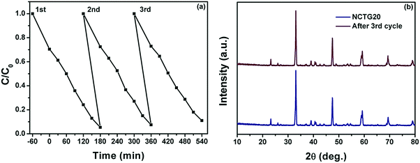 | ||
| Fig. 12 (a) Photocatalyst reusability up to three cycles and (b) PXRD pattern of NCTG20 before and after the third cycle. | ||
3.11. Proposed mechanism for photocatalytic activity
The role of graphene based semiconductor photocatalysts in the transfer of photogenerated charge carriers for pollutant degradation reactions is still controversial. Most of the reported mechanisms on graphene based photocatalyst materials revealed the role of graphene as an acceptor of photogenerated electrons from the CB of a semiconductor because of its special π-conjugation structure and high conductivity.4,62,63 In terms of work function, the more negative work function of graphene (−4.42 eV) in comparison with that of the coupled material allows the transfer of electrons from the CB of the semiconductor to the graphene and reveals its electron accepting behavior. For example in the case of the TiO2–graphene photocatalyst, in which the work function of graphene and TiO2 is −4.42 and −4.40 eV, respectively, graphene acts as an electron acceptor.62,64 Another attractive mechanistic possibility studied involves the transfer of electrons from graphene to the CB of a semiconductor material, provided the work function of the material is more positive in comparison with that of graphene. In this case, graphene acts as a photosensitizer (electron donor) and this concept is also well reported.65,66 Zhaung et al. have reported an interesting concept for the photogenerated charge transfer in graphene–SnO2 aerosols for the degradation of RhB in which co-photosensitization of the dye and graphene plays an important role in the degradation mechanism. Lee and co-workers have reported graphene wrapped-TiO2 nanoparticles for the degradation of MB in visible light and explained the concept of co-photosensitization in the degradation mechanism. In our case, the work function values of MB*, graphene and NCT are −3.60, −4.42 and −3.67 eV, respectively, calculated by using the equation E (eV)= −4.5 – ENHE (V).67 Thus, the mechanism of MB degradation may involve the following different processes.67–69(i) Transfer of electrons from MB* to graphene causing photosensitization, which is thermodynamically favored.
(ii) Direct electron transfer from MB* to the CB of NCT.
(iii) Transfer of electrons from MB* to the CB of NCT via graphene causing co-photosensitization, which is thermodynamically less favored.
(iv) Excitation of electrons from VB to CB of NCT by visible light absorption.
(v) Transfer of electrons from the CB of NCT to the graphene, which is highly favored in this case.
However, based on the obtained experimental results, some of the above mentioned possibilities could be ruled out. The PL spectra of the NCTG20 (Fig. 11) composite show an emission with less intensity as compared to pristine CT and NCT suggesting a decrease in electron–hole recombination. There is no enhancement in the PL emission range which strengthens the view that there is no contribution of electrons from graphene to NCT.68 In control experiments, the degradation of bare MB solution under visible light was found to be negligible but small degradation is observed in the presence of RGO. Thus, we propose that the dye photosensitization as well as the photocatalytic action of the RGO–NCT composite are responsible for the degradation of MB. A plausible mechanism of MB dye degradation using the RGO–NCT composite is illustrated in Scheme 1.
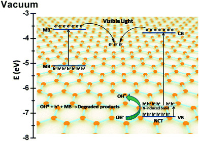 | ||
| Scheme 1 Schematic illustration of the mechanism of photogenerated charge transfer and the photocatalytic process over RGO–NCT photocatalysts under visible light irradiation. | ||
To support the proposed mechanism and to gain insight into the role of reactive species involved in the degradation of MB, active species trapping experiments were performed. Various scavengers were used, including triethanolamine (TEA), isopropanol (IPA) and benzoquinone (BQ) for the quenching of h+, *OH and O2−*, respectively.24 The photocatalytic degradation of MB with the NCTG20 composite was carried out under visible light in the presence of these scavengers and monitored with the help of UV-visible spectroscopy. Fig. 13 compares the formation of various active species during the photocatalytic degradation reaction. It was found that the photocatalytic degradation of MB was not much affected by the addition of BQ and TEA indicating that the mechanism is not dominated by super oxide anion radicals (O2−*) and holes (h+) in the photodegradation process. However, the degradation was drastically quenched by the addition of IPA indicating that the dominant reactive species controlling the photocatalytic degradation of MB are hydroxyl radicals (*OH). Therefore, it can be concluded that the species affecting degradation is in the order of *OH > h+ > O2−*.
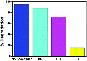 | ||
| Fig. 13 Reactive oxygen species trapping of the NCTG20 composite using IPA, BQ and TEA under visible light irradiation. | ||
These experimental findings are further supported by the theoretical predictions also. The CB and VB edge potential of NCT are calculated by applying the well known Mulliken electronegativity theory and found to be −0.83 and +2.67 eV, respectively.70 The formation of O2−* radicals is facilitated by the lower negative reduction potential of O2/O2− (−0.33 eV) in comparison with that of the CB edge but the transfer of electrons from CB of NCT to the graphene does not allow the reaction of photogenerated electrons with O2 to reduce it into O2−* radical anions as suggested by PL spectroscopic study. Also the VB edge of NCT (+2.67 eV) and the standard redox potentials of *OH/H2O (+2.68 eV) and *OH/OH− (+1.99 eV) allow the formation of OH* radicals by the reaction of photogenerated holes present in the valence band with H2O or OH−.19 The migration of electrons from the excited state of MB* to graphene also leads to charge separation and the holes generated in the ground state of MB can be utilized for its self-degradation. Hence h+ and OH* radicals are the dominating active species in the photocatalytic degradation of MB.
However, in the case of TBZ degradation, this mechanism may not fit well. TBZ being a colorless pollutant does not undergo photosensitization and self-degradation. In this case, the electron accepting behavior of graphene comes into play and the transfer of photogenerated electrons from the CB of NCT to graphene is favored here. This leads to efficient charge separation as confirmed by PL spectroscopy and hence leads to the enhanced photocatalytic activity of the NCTG20 composite as compared to the bare NCT.
4. Conclusions
In summary, we have successfully synthesized nitrogen doped CaTiO3 supported on RGO nanosheets (RGO–NCT composites) for the first time and demonstrated their enhanced photocatalytic activity under visible light for the degradation of a colored dye (MB) and a colorless pollutant (TBZ). The as synthesized RGO–NCT composites are demonstrated as efficient bifunctional photocatalysts to perform both adsorption and photocatalysis for the enhanced degradation of MB and TBZ under visible light irradiation. The NCTG20 composite is found to be the best photocatalyst among all as it shows maximum adsorption and degradation of the examined pollutants. The enhanced adsorption can be ascribed to the graphene content present in the catalyst and it also helps to reduce the photogenerated charge recombination to enhance the photocatalytic activity. Moreover, the commendable stability and recyclability of the best catalyst is also demonstrated. Significantly, the synergetic effect of photosensitization of the dye and photocatalytic action of the working photocatalyst is explained to propose the photocatalytic mechanism in terms of photogenerated charge carrier transfer. This work provides a good example for the design of efficient, visible light driven and recyclable perovskite-based bifunctional photocatalysts for environmental remediation.Conflicts of interest
The authors declare no competing financial interest.Acknowledgements
We acknowledge the Advanced Materials Research Center (AMRC), IIT Mandi for the laboratory and the characterization facilities. We thank Dr Kaustava Bhattacharyya for his kind help with regard to XPS investigations. VK acknowledges the financial support from the Department of Science and Technology (DST), India, under the Young Scientist Scheme (YSS/2014/000456). SK and AB are thankful to UGC, India and CSIR, India for their senior research fellowships, respectively. VS and AK acknowledges the scholarship from MHRD, India.References
- S. Kumar, A. Kumar, A. Bahuguna, V. Sharma and V. Krishnan, Beilstein J. Nanotechnol., 2017, 8, 1571–1600 CrossRef PubMed.
- M. R. Hoffmann, S. T. Martin, W. Choi and D. W. Bahnemann, Chem. Rev., 1995, 95, 69–96 CrossRef CAS.
- P. Kanhere and Z. Chen, Molecules, 2014, 19, 19995–20022 CrossRef CAS PubMed.
- Q. Xiang, J. Yu and M. Jaroniec, Chem. Soc. Rev., 2012, 41, 782–796 RSC.
- W. Wang, M. O. Tadé and Z. Shao, Chem. Soc. Rev., 2015, 44, 5371–5408 RSC.
- H. Zhang, X. Lv, Y. Li, Y. Wang and J. Li, ACS Nano, 2009, 4, 380–386 CrossRef PubMed.
- C. Chen, W. Cai, M. Long, B. Zhou, Y. Wu, D. Wu and Y. Feng, Acs Nano, 2010, 4, 6425–6432 CrossRef CAS PubMed.
- S. Kumar, N. L. Reddy, H. S. Kushwaha, A. Kumar, M. V. Shankar, K. Bhattacharyya, A. Halder and V. Krishnan, ChemSusChem, 2017 DOI:10.1002/cssc.201701024.
- S. Huang, S. Guo, Q. Wang, N. Zhu, Z. Lou, L. Li, A. Shan and H. Yuan, ACS Appl. Mater. Interfaces, 2015, 7, 20170–20178 CAS.
- M. Jiménez, M. Ignacio Maldonado, E. M. Rodríguez, A. Hernández-Ramírez, E. Saggioro, I. Carra and J. A. Sánchez Pérez, J. Chem. Technol. Biotechnol., 2015, 90, 149–157 CrossRef.
- A. Alzahrani, D. Barbash and A. Samokhvalov, J. Phys. Chem. C, 2016, 120, 19970–19979 CAS.
- T. Wang, C. Li, J. Ji, Y. Wei, P. Zhang, S. Wang, X. Fan and J. Gong, ACS Sustainable Chem. Eng., 2014, 2, 2253–2258 CrossRef CAS.
- X. Huang, X. Qi, F. Boey and H. Zhang, Chem. Soc. Rev., 2012, 41, 666–686 RSC.
- W. Liu, J. Cai and Z. Li, ACS Sustainable Chem. Eng., 2015, 3, 277–282 CrossRef CAS.
- Q. Xiang, D. Lang, T. Shen and F. Liu, Appl. Catal., B, 2015, 162, 196–203 CrossRef CAS.
- G.-L. He, M.-J. Chen, Y.-Q. Liu, X. Li, Y.-J. Liu and Y.-H. Xu, Appl. Surf. Sci., 2015, 351, 474–479 CrossRef CAS.
- B. Bajorowicz, J. Reszczyńska, W. Lisowski, T. Klimczuk, M. Winiarski, M. Słoma and A. Zaleska-Medynska, RSC Adv., 2015, 5, 91315–91325 RSC.
- T. Xian, H. Yang, Y. Huo, J. Ma, H. Zhang, J. Su and W. Feng, J. Nanosci. Nanotechnol., 2016, 16, 570–575 CrossRef CAS PubMed.
- T. Xian, H. Yang and Y. Huo, Phys. Scr., 2014, 89, 115801 CrossRef.
- D. Weixia, B. Qifu, G. Xingyong and Z. Gaoling, J. Ceram. Soc. Jpn., 2015, 123, 643–648 CrossRef.
- H. Zhao, Y. Duan and X. Sun, New J. Chem., 2013, 37, 986–991 RSC.
- Y. Wang, C.-G. Niu, L. Wang, Y. Wang, X.-G. Zhang and G.-M. Zeng, RSC Adv., 2016, 6, 47873–47882 RSC.
- J. Jang, P. Borse, J. S. Lee, K. Lim, O. Jung, E. Jeong, J. Bae and H. Kim, Bull. Korean Chem. Soc., 2011, 32, 95–99 CrossRef CAS.
- H. Zhang, G. Chen, X. He and J. Xu, J. Alloys Compd., 2012, 516, 91–95 CrossRef CAS.
- H. Zhang, G. Chen, Y. Li and Y. Teng, Int. J. Hydrogen Energy, 2010, 35, 2713–2716 CrossRef CAS.
- S. Nishimoto, M. Matsuda and M. Miyake, Chem. Lett., 2006, 35, 308–309 CrossRef CAS.
- S. Kumar, S. Tonda, A. Baruah, B. Kumar and V. Shanker, Dalton Trans., 2014, 43, 16105–16114 RSC.
- D.-R. Liu, Y.-S. Jiang and G.-M. Gao, Chemosphere, 2011, 83, 1546–1552 CrossRef CAS PubMed.
- F. Zou, Z. Jiang, X. Qin, Y. Zhao, L. Jiang, J. Zhi, T. Xiao and P. P. Edwards, Chem. Commun., 2012, 48, 8514–8516 RSC.
- I. Ali, Chem. Rev., 2012, 112, 5073–5091 CrossRef CAS PubMed.
- X. Zhang, J. Zhang, Y. Jin, H. Zhao and X.-j. Wang, Cryst. Growth Des., 2008, 8, 779–781 CAS.
- S. Kumar, V. Sharma, K. Bhattacharyya and V. Krishnan, New J. Chem., 2016, 40, 5185–5197 RSC.
- S. Kumar, V. Sharma, K. Bhattacharyya and V. Krishnan, Mater. Chem. Front., 2017, 1, 1093–1106 RSC.
- S. Lan, L. Liu, R. Li, Z. Leng and S. Gan, Ind. Eng. Chem. Res., 2014, 53, 3131–3139 CrossRef CAS.
- S. K. Mishra, S. N. Tripathi, V. Choudhary and B. D. Gupta, Sens. Actuators, B, 2014, 199, 190–200 CrossRef CAS.
- J. Xu, Y. Wei, Y. Huang, J. Wang, X. Zheng, Z. Sun, L. Fan and J. Wu, Ceram. Int., 2014, 40, 10583–10591 CrossRef CAS.
- R.-X. Wang, Q. Zhu, W.-S. Wang, C.-M. Fan and A.-W. Xu, New J. Chem., 2015, 39, 4407–4413 RSC.
- T. Xian, H. Yang, L. Di, J. Ma, H. Zhang and J. Dai, Nanoscale Res. Lett., 2014, 9, 1–9 CrossRef CAS PubMed.
- G. Dong, X. Xiao, L. Zhang, Z. Ma, X. Bao, M. Peng, Q. Zhang and J. Qiu, J. Mater. Chem., 2011, 21, 2194–2203 RSC.
- H. Zheng, G. C. de Györgyfalva, R. Quimby, H. Bagshaw, R. Ubic, I. Reaney and J. Yarwood, J. Eur. Ceram. Soc., 2003, 23, 2653–2659 CrossRef CAS.
- H. Liu, G. Zhang, Y. Zhou, M. Gao and F. Yang, J. Mater. Chem. A, 2013, 1, 13902–13913 CAS.
- C. Chen, M. Long, M. Xia, C. Zhang and W. Cai, Nanoscale Res. Lett., 2012, 7, 101 CrossRef PubMed.
- X. Xu, T. Wu, F. Xia, Y. Li, C. Zhang, L. Zhang, M. Chen, X. Li, L. Zhang and Y. Liu, J. Power Sources, 2014, 266, 282–290 CrossRef CAS.
- S. Yoon, E. H. Otal, A. E. Maegli, L. Karvonen, S. K. Matam, S. Riegg, S. G. Ebbinghaus, J. C. Fallas, H. Hagemann and B. Walfort, Opt. Mater. Express, 2013, 3, 248–259 CrossRef CAS.
- L. Lozano-Sanchez, S.-W. Lee, T. Sekino and V. Rodríguez-González, CrystEngComm, 2013, 15, 2359–2362 RSC.
- D. Mondal, J. P. Chaudhary, M. Sharma and K. Prasad, RSC Adv., 2014, 4, 29834–29839 RSC.
- C. Han, J. Liu, W. Yang, Q. Wu, H. Yang and X. Xue, J. Photochem. Photobiol., A, 2016, 322, 1–9 Search PubMed.
- K. Bhattacharya, A. Tripathi, G. Dey and N. Gupta, J. Nanosci. Nanotechnol., 2005, 5, 790–796 CrossRef CAS PubMed.
- R. G. Nair, S. Mazumdar, B. Modak, R. Bapat, P. Ayyub and K. Bhattacharyya, J. Photochem. Photobiol., A, 2017, 345, 36–53 CrossRef CAS.
- H. Tan, Z. Zhao, W.-b. Zhu, E. N. Coker, B. Li, M. Zheng, W. Yu, H. Fan and Z. Sun, ACS Appl. Mater. Interfaces, 2014, 6, 19184–19190 CAS.
- K. Bhattacharyya, J. Majeed, K. K. Dey, P. Ayyub, A. Tyagi and S. Bharadwaj, J. Phys. Chem. C, 2014, 118, 15946–15962 CAS.
- K. Zhou, Y. Zhu, X. Yang, X. Jiang and C. Li, New J. Chem., 2011, 35, 353–359 RSC.
- S. H. Borji, S. Nasseri, A. H. Mahvi, R. Nabizadeh and A. H. Javadi, J. Environ. Health Sci. Eng., 2014, 12, 101 CrossRef PubMed.
- L. Chen, J. Yang, X. Zeng, L. Zhang and W. Yuan, Mater. Express, 2013, 3, 281–290 CrossRef CAS.
- G. Ramesha, A. V. Kumara, H. Muralidhara and S. Sampath, J. Colloid Interface Sci., 2011, 361, 270–277 CrossRef CAS PubMed.
- B. Li, H. Cao, J. Yin, Y. A. Wu and J. H. Warner, J. Mater. Chem., 2012, 22, 1876–1883 RSC.
- J. Wang, T. Tsuzuki, B. Tang, X. Hou, L. Sun and X. Wang, ACS Appl. Mater. Interfaces, 2012, 4, 3084–3090 CAS.
- S. Khanchandani, S. Kumar and A. K. Ganguli, ACS Sustainable Chem. Eng., 2016, 4, 1487–1499 CrossRef CAS.
- A. Bhirud, S. Sathaye, R. Waichal, C.-J. Park and B. Kale, J. Mater. Chem. A, 2015, 3, 17050–17063 CAS.
- J. Yu, G. Dai, Q. Xiang and M. Jaroniec, J. Mater. Chem., 2011, 21, 1049–1057 RSC.
- J. Hou, Z. Wang, W. Kan, S. Jiao, H. Zhu and R. Kumar, J. Mater. Chem., 2012, 22, 7291–7299 RSC.
- G. Williams, B. Seger and P. V. Kamat, ACS Nano, 2008, 2, 1487–1491 CrossRef CAS PubMed.
- Q. Li, B. Guo, J. Yu, J. Ran, B. Zhang, H. Yan and J. R. Gong, J. Am. Chem. Soc., 2011, 133, 10878–10884 CrossRef CAS PubMed.
- P. V. Kamat, J. Phys. Chem. Lett., 2011, 2, 242–251 CrossRef CAS.
- Y. Zhang, N. Zhang, Z.-R. Tang and Y.-J. Xu, Acs Nano, 2012, 6, 9777–9789 CrossRef CAS PubMed.
- A. Du, Y. H. Ng, N. J. Bell, Z. Zhu, R. Amal and S. C. Smith, J. Phys. Chem. Lett., 2011, 2, 894–899 CrossRef CAS PubMed.
- B. Li and H. Cao, J. Mater. Chem., 2011, 21, 3346–3349 RSC.
- J. S. Lee, K. H. You and C. B. Park, Adv. Mater., 2012, 24, 1084–1088 CrossRef CAS PubMed.
- S. Zhuang, X. Xu, B. Feng, J. Hu, Y. Pang, G. Zhou, L. Tong and Y. Zhou, ACS Appl. Mater. Interfaces, 2013, 6, 613–621 Search PubMed.
- S. Wang, D. Li, C. Sun, S. Yang, Y. Guan and H. He, Appl. Catal., B, 2014, 144, 885–892 CrossRef CAS.
Footnote |
| † Electronic supplementary information (ESI) available: XRD and Raman spectra of GO and RGO (Fig. S1 and S2). Elemental mapping images of CT and NCT (Fig. S3 and S4). A plot of transformed Kubelka–Munk function vs. the energy of light for CT and NCT (Fig. S5). Time dependent absorption spectra of MB and TBZ degradation under dark and light conditions (Fig. S6 and S7). Summary of kinetics data of photocatalytic degradation of MB using all prepared photocatalysts under visible light irradiation (Table S1). Adsorption/degradation study of MB over the NCTG20 composite (Fig. S8). Summary of adsorption parameters (Table S2). Raman spectra of MB and recovered catalysts after third cycle (Fig. S9). Mass spectra of MB solution degraded using NCTG20 composite under visible light irradiation (Fig. S10). See DOI: 10.1039/c7qm00362e |
| This journal is © the Partner Organisations 2017 |

