 Open Access Article
Laser induced MoS2/carbon hybrids for hydrogen evolution reaction catalysts†
Heng
Deng
a,
Chi
Zhang
a,
Yunchao
Xie
a,
Travis
Tumlin
a,
Lily
Giri
bc,
Shashi P.
Karna
b and
Jian
Lin
 *a
*a
aDepartment of Mechanical & Aerospace Engineering, University of Missouri, Columbia, Missouri 65211, USA. E-mail: LinJian@missouri.edu
bU.S. Army Research Laboratory, Weapons and Materials Research Laboratory, ATTN: RDRL-WM, Aberdeen Proving Ground, MD 21005-5069, USA
cORISE Research Associate, USA
First published on 5th February 2016
Abstract
MoS2/carbon hybrid materials have been shown to be promising non-precious metal electrocatalysts for the hydrogen evolution reaction (HER). However, a facile method for synthesizing them is still a big challenge, let alone patterning them through a design. In this work, we present a novel strategy to synthesize and pattern MoS2/carbon hybrid materials as electrocatalysts for the HER through a one-step direct laser writing (DLW) method under ambient conditions. DLW on citric acid–Mo–S precursors leads to the in situ synthesis of small-sized MoS2 nanoparticles (NPs) anchored to the carbon matrix. Largely exposed catalytically active sites from the MoS2 NPs and the synergetic effect from the carbon matrix make the hybrid materials exhibit superior catalytic performance and stability for the HER in acidic solutions. Through computer-controlled laser beams we can design arbitrary patterns made of these catalysts on targeted substrates, which will open a new route for fabricating on-chip microfuel cells or catalytic microreactors.
The direct laser writing (DLW) method has emerged as a novel technique for fabricating nanostructures with low cost, high efficiency and flexible designability.1–3 In the past decade we have witnessed intensive efforts to extend this DLW method to research areas, such as fabricating photonic crystals, transferring graphite into nanodiamond and reducing graphite oxide.1,4,5 Compared to conventional fabrication methods, DLW's in situ growth and patterning capability with high designability enables materials to be grown at desired locations. Moreover, the laser-induced nanomaterials undergo rapid nucleation and crystal growth, which is very fundamentally interesting. For example, the laser-induced 3D porous graphene from polyimide films could be directly made into microsupercapacitors by one-step laser writing.2,6 This ability has a potential benefit for the fabrication of microdevices such as microfuel cells and microreactors, into which catalysts need to be integrated.7,8 By using the DLW method, the catalysts could be in situ synthesized and patterned inside the microdevices, which avoids the complicated and expensive process of integration.9 Even though in situ synthesizing and patterning of the catalysts by DLW shows bright potential, this field is still in its infancy.
To conceptually verify this idea, the most popular hydrogen evolution reaction (HER) catalysts–molybdenum disulfide (MoS2) nanoparticles (NPs)/carbon hybrids–were targeted in this work. MoS2 NPs synergized with carbon materials, which exploit the merits of both components, have emerged as a new paradigm for the HER.10–12 On one hand, the layered transition metal dichalcogenide MoS2 offers abundant exposed catalytically active sites to facilitate the HER.13,14 On the other hand, carbon materials, such as graphene, carbon nanotubes, and amorphous carbon, endow the MoS2 with good electrical conductivity, a high surface area, and even more active edge sites, which enhance the catalytic performance of MoS2.15–17 Until now, hydrothermal and pyrolysis methods have been the mainstream strategies to produce MoS2/carbon hybrid materials.15,18,19 With these traditional methods, it is impossible to pattern the catalysts through a design directly. Moreover, these methods themselves also show several inevitable drawbacks. For example, in the hydrothermal method, graphene oxide (GO) was prepared and used to reduce the precursor of MoS2.15,19 The main challenge of this method is the synthesis of GO, which often involves a large consumption of unrecyclable solvents and strong acids and requires a considerable synthesis time. As for the pyrolysis method, it replaces GO with other cheap carbon sources, but rigorous reaction conditions of high temperature and inert gas atmosphere hinder its practical applications.18 In this scenario, DLW is more economic and facile. In addition to its precise patterning capability, DLW also possesses other features like laser induced transient high temperature (>1500 °C) and pressure (2–100 GPa), which provide a unique reaction route to synthesizing nanomaterials.2,4 Moreover, the whole process of fabrication can be performed under ambient conditions and finished in a short period of time, which has shown the potential of the roll-to-roll manufacturing.2
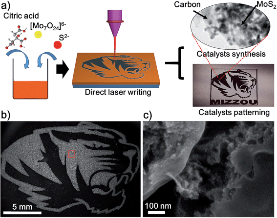
Herein, we adopt a novel design strategy of using the DLW method to synthesize and pattern the MoS2/carbon hybrids from cheap starting materials composed of citric acid (C6H8O7), ammonium molybdate tetrahydrate ((NH4)6Mo7O24·4H2O) and sodium sulfide (Na2S). Under the conditions of high transient temperature and pressure generated by laser induction, MoS2 NPs and amorphous carbon are formed simultaneously. Additionally, the precision afforded with the computer controlled laser also allows for the patterning of MoS2/carbon hybrids directly onto glass substrates. The fabrication procedure is illustrated in Fig. 1a and explained in detail in the ESI.† First, ammonium molybdate, sodium sulfide and citric acid (CA) were dissolved in deionized water. Then the solution was dropped onto the surface of glass slides and a brownish film was formed after the removal of the water under a vacuum oven. According to the previous studies,20 when mixed with citric acid and sodium sulphide, ammonium molybdate is converted into ammonium thiomolybdate, which could be further decomposed into MoS2 at a high temperature. Finally we employed the CO2 laser to carbonize CA and decompose ammonium thiomolybdate into MoS2 NPs simultaneously, resulting in the MoS2/carbon hybrids. After optimizing the recipe, we fixed the molar ratio of Mo![[thin space (1/6-em)]](https://www.rsc.org/images/entities/char_2009.gif) :
:![[thin space (1/6-em)]](https://www.rsc.org/images/entities/char_2009.gif) S to 1
S to 1![[thin space (1/6-em)]](https://www.rsc.org/images/entities/char_2009.gif) :
:![[thin space (1/6-em)]](https://www.rsc.org/images/entities/char_2009.gif) 3, in which S was a little superfluous to compensate the loss of S because Na2S may become H2S and escape from the precursors. Then we change the ratios of CA in these recipes. During the process optimization, we noted that CA has several important roles: (1) CA has been demonstrated as a good precursor for carbon nanomaterials; (2) CA promotes the transformation of ammonium molybdate and sodium sulfide into ammonium thiomolybdate;20 (3) CA exhibits a certain viscidity, which could be used as a medium to bond ammonium molybdate and sodium sulfide together to form a homogeneous solid film. With no CA or a low concentration of CA, no homogeneous or continuous films were achieved (Fig. S1†). The detailed impact of CA on the electrocatalytic performance of laser-induced MoS2/carbon hybrids will be discussed below. After optimization we obtained a recipe with a Mo
3, in which S was a little superfluous to compensate the loss of S because Na2S may become H2S and escape from the precursors. Then we change the ratios of CA in these recipes. During the process optimization, we noted that CA has several important roles: (1) CA has been demonstrated as a good precursor for carbon nanomaterials; (2) CA promotes the transformation of ammonium molybdate and sodium sulfide into ammonium thiomolybdate;20 (3) CA exhibits a certain viscidity, which could be used as a medium to bond ammonium molybdate and sodium sulfide together to form a homogeneous solid film. With no CA or a low concentration of CA, no homogeneous or continuous films were achieved (Fig. S1†). The detailed impact of CA on the electrocatalytic performance of laser-induced MoS2/carbon hybrids will be discussed below. After optimization we obtained a recipe with a Mo![[thin space (1/6-em)]](https://www.rsc.org/images/entities/char_2009.gif) :
:![[thin space (1/6-em)]](https://www.rsc.org/images/entities/char_2009.gif) S
S![[thin space (1/6-em)]](https://www.rsc.org/images/entities/char_2009.gif) :
:![[thin space (1/6-em)]](https://www.rsc.org/images/entities/char_2009.gif) CA molar ratio of 1
CA molar ratio of 1![[thin space (1/6-em)]](https://www.rsc.org/images/entities/char_2009.gif) :
:![[thin space (1/6-em)]](https://www.rsc.org/images/entities/char_2009.gif) 3
3![[thin space (1/6-em)]](https://www.rsc.org/images/entities/char_2009.gif) :
:![[thin space (1/6-em)]](https://www.rsc.org/images/entities/char_2009.gif) 2, which is used to illustrate the process and properties of materials in the following experiments.
2, which is used to illustrate the process and properties of materials in the following experiments.
Using computer-controlled laser scribing, MoS2/carbon hybrids were readily written into delicate geometry as shown in the optical image of Fig. 1a. It shows two distinct areas: the black Mizzou tiger logo after the precursor was exposed to the laser, and the brown unexposed area. Because the laser-induced carbon possessed a good electrical conductivity, the exposed areas look brighter in the dark-field scanning electron microscopy (SEM) image (Fig. 1b). When the exposed areas are magnified in Fig. 1b, the morphology of MoS2 and carbon can be clearly observed (Fig. 1c). The obtained MoS2 nanoparticles (NPs) were dispersed homogeneously in the carbon matrix (Fig. 1c and S2†). This was further confirmed by the corresponding energy dispersive X-ray (EDS) elemental mapping images of elemental C, S, and Mo (Fig. S3†). The laser induced carbon has two advantages for the HER: (1) it exhibits a good electrical conductivity which would enhance the electron transfer rate in the HER;17 (2) it effectively disperses the MoS2 NPs, which would enhance the accessible surface areas of MoS2 NPs and further improve their catalytic performance. Moreover, the DLW method can artfully achieve synthesis and pattering of the catalysts in one step. Although similar MoS2/carbon hybrid materials have been synthesized by other methods such as hydrothermal and pyrolysis methods,10,15,16 patterning them cannot be achieved by these methods, which highlights the distinct advantage of the DLW method.
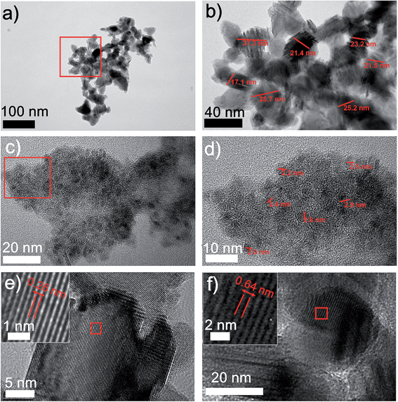
The structures of the MoS2/carbon hybrid materials were further investigated using transmission electron microscopy (TEM). TEM images and the electron diffraction pattern (Fig. S4†) exhibit the distinct carbon and MoS2 NPs. We observed two types of MoS2 NPs with two different sizes (Fig. 2). In addition to the 20–40 nm MoS2 NPs (Fig. 2a and b) we also obtained 2–3 nm MoS2 quantum dots (QDs) which are uniformly anchored to the carbon sheets (Fig. 2c and d). Usually, the ultra-small feature of MoS2 QDs would possess more active sites, which guarantee a better HER catalytic activity.21 These two distinguished size distributions could be attributed to the short laser pulse as well as the high localized pressure generated by the laser induction. On one hand, in a pulse of 14 μs, the growth of MoS2 NPs was sufficiently limited, leading to MoS2 NPs with sizes smaller than 40 nm. On the other hand, the top surfaces of the precursor films which are directly exposed to the laser undergo a higher pressure condition than the underneath locations due to laser ablation. It will further inhibit the crystal's growth, preventing NPs from growing to bigger sizes. Thus, we presume that the 2–3 nm MoS2 QDs are produced from the top surfaces of the films, while 20–40 nm MoS2 NPs are more likely to form from underneath surfaces. Furthermore, the lattice fringes of MoS2 NPs can be clearly seen in the HRTEM images (Fig. 2e and f). Typical lamellar structures of MoS2 with a lattice spacing of 0.26 nm and 0.62 nm correspond to (002) and (100) planes of MoS2, respectively.18 Meanwhile, the laser induced carbon from CA serves as a conductive matrix to stabilize the MoS2 NPs. These effects make DLW a novel fabrication method to generate ultra-fine nanomaterials by mediating the nucleation and growth of NPs.
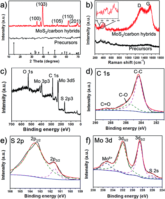
To further analyze the structures and compositions of the obtained MoS2/carbon hybrids, we employed X-ray diffraction (XRD), Raman spectroscopy and X-ray photoelectron spectroscopy (XPS). Before laser induction, no peaks can be observed in the XRD pattern. But after laser exposure, as shown in Fig. 3a, the MoS2/carbon hybrids show prominent XRD peaks at 34.7°, 39.2°, 52.2°, 62.4°, and 69.3°, which correspond to the (100), (103), (105), (110) and (201) planes of MoS2 (JCPDS no. 37-1492).22 To detect the carbon materials, Raman spectroscopy is a powerful tool. We obtain two distinct Raman spectra of materials before and after laser induction (Fig. 3b). A typical Raman spectrum of the MoS2/carbon hybrids shows peaks at ∼1353 and 1586 cm−1, which correspond to the G and D peaks of amorphous carbon, suggesting the carbonization of citric acid.18 Moreover, the peaks of A1g at 408 cm−1 and E12g at 382 cm−1 (inset of Fig. 3b) represent the vibration modes of out-plane and in-plane Mo–S phonon modes. These results further confirm the formation of MoS2.23 The peaks in the range from 300 cm−1 to 500 cm−1 in the Raman spectra of the precursors could result from the vibration modes of Mo–S in ammonium tetrathiomolybdate. The chemical nature and bonding states of C, S and Mo elements in the MoS2/carbon hybrids were investigated by XPS. The survey of the obtained hybrid materials shown in Fig. 3c exhibits the peaks for O, C, S, and Mo. The oxygen peak could result from amorphous carbon derived from CA. The carbon peak could result from amorphous carbon derived from CA. The binding energies of C 1s centered at 285.0 eV, 286 eV and 288.5 eV could be assigned to C–C, C–O and C![[double bond, length as m-dash]](https://www.rsc.org/images/entities/char_e001.gif) O bonding, respectively (Fig. 3d). The peaks at about 161.85 eV and 162.8 eV are related to S 2p3/2 and S 2p1/2 binding energies, respectively (Fig. 3e).17 The peaks at 228.6 and 231.8 eV shown in Fig. 3f are associated with 3d3/2 and 3d5/2 of Mo4+, and the small peak at 235.4 eV can be ascribed to Mo6+ resulting from the slight surface oxidation of MoS2 in air.24,25 These results agree well with the ones from XRD, Raman spectroscopy, and TEM.
O bonding, respectively (Fig. 3d). The peaks at about 161.85 eV and 162.8 eV are related to S 2p3/2 and S 2p1/2 binding energies, respectively (Fig. 3e).17 The peaks at 228.6 and 231.8 eV shown in Fig. 3f are associated with 3d3/2 and 3d5/2 of Mo4+, and the small peak at 235.4 eV can be ascribed to Mo6+ resulting from the slight surface oxidation of MoS2 in air.24,25 These results agree well with the ones from XRD, Raman spectroscopy, and TEM.
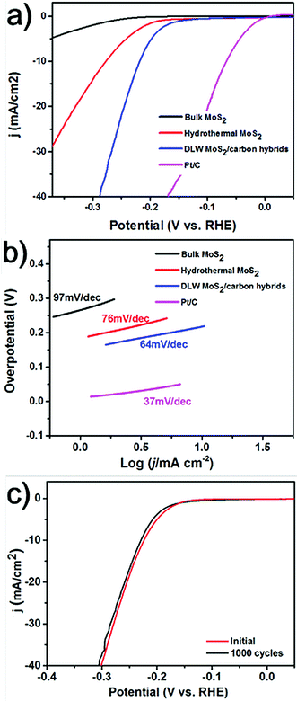
The DLW method can realize the synthesis of MoS2 NPs in a short period of time. For comparison, the conventional hydrothermal method was adopted to synthesize MoS2 using the same molar ratio of chemicals as for the DLW method. And it usually requires a long reaction time of over 20 hours. Using the hydrothermal method we obtained aggregated MoS2 flakes with diameters in the order of several hundred nanometers (Fig. S5†). It is well known that the size of catalytic particles significantly influences the performance of electrocatalysts. In general, smaller sizes guarantee more catalytically active sites and better catalytic performance.26 Thus, we expect that laser induced MoS2 NPs anchored in the carbon matrix will outperform those produced by the hydrothermal method. To investigate this, we measured the HER activity of laser induced MoS2/carbon hybrids, in comparison with hydrothermal MoS2, and bulk MoS2. These catalysts were deposited on a glassy carbon working electrode with a mass loading of 0.2 mg cm−2. Electrochemical measurements were carried out using a standard three-electrode setup in H2 saturated 0.5 M H2SO4 electrolytes. A saturated silver chloride and a graphite rod were used as the reference electrode and the counter electrode, respectively. The detailed methods can be found in the ESI.† As a reference, the electrocatalysis of the commercial Pt catalyst (20 wt% Pt on Vulcan carbon black) was also tested. Fig. 4a shows the polarization curves of all the catalysts by performing linear sweep voltammetry (LSV) measurements. Pt/C exhibits the expected HER activity with a near zero overpotential. Due to its bulk size and a small surface area, the bulk MoS2 shows the poorest catalytic activity for the HER. The overpotential at an output current density of 10 mA cm−2 (termed as η10) for hydrothermal MoS2 is 278 mV. Laser induced MoS2/carbon hybrids show the best catalytic performance among all of the three, which exhibit an η10 of 216 mV. To further understand the improved HER performance of the DLW MoS2/carbon hybrid in comparison to that of hydrothermal MoS2, their electrochemically active surface areas (ECSAs) were estimated from the electrochemical double-layer capacitance by collecting cyclic voltammetry curves (Fig. S6†). The calculated value of ECSA for the DLW MoS2/carbon hybrid was ∼70 cmECSA2, significantly higher than that of hydrothermal MoS2 (∼5 cmECSA2, Fig. S6†). Normally higher ECSAs allow more effective accessibility of active sites.27 We also calculated the quantity of active sites on these two types of MoS2/carbon hybrids. The value of 9.33 × 10⁻⁷ mol mg−1 for DLW MoS2/carbon hybrids was over one order magnitude higher than that of hydrothermal MoS2 (3.83 × 10⁻⁸ mol mg−1) (Fig. S7†). These pieces of evidence unambiguously confirmed that enhanced electrocatalytic activities of laser induced MoS2/carbon hybrids can be attributed to the small-sized MoS2 NPs and their uniform distribution in the carbon matrix. Moreover, DLW MoS2/carbon hybrids show a better HER performance than the reported pure MoS2 quantum dots.25 This indicates that the carbon matrix would facilitate electron transfer, thus enhancing the HER activity of MoS2.17 To further test this effect we utilized different molar ratios of CA in the precursors. Polarization curves shown in Fig. S8† indicate that as the ratio of CA increases the HER performance first increases and then decreases when it is over a threshold value. The reason could be that as the carbon content increases in the hybrids the charge transfer rate will increase first due to the facilitation from the carbon matrix. If the value is over the threshold, the excessive amorphous carbon may start to block proton transfer to the active sites, leading to decreased HER activity.
HER usually involves Volmer, Heyrovsky, and Tafel reactions as shown in formulas (1), (2) and (3).
| H+ + M + e → M–H* (Volmer reaction) | (1) |
| M–H* + H+ + e → H2 + M (Heyrovsky reaction) | (2) |
| 2M–H* → H2 + 2M (Tafel reaction) | (3) |
Finally, we tested the long-term stability of laser-induced MoS2/carbon hybrids. It is an important aspect to evaluate the performance of an electrocatalyst. The continuous cyclic voltammetry (CV) in the cathodic potential window from −300 mV to 300 mV was performed over 1000 cycles. Fig. 4c shows the comparison of polarization curves of the materials during the first cycle and 1000th cycle. The almost overlapped curves indicate the negligible loss of the catalytic performance and a remarkable stability of the catalysts.
In summary, we report a novel DLW method to synthesize and pattern the MoS2/carbon hybrids from the economic starting materials of ammonium molybdate, sodium sulfide, and CA. We obtained MoS2 NPs including 20–40 nm NPs and 2–3 nm QDs anchored to the carbon matrix. Due to the dual effect from small-sized MoS2 NPs with enhanced catalytic sites and the conductive carbon matrix, the electrocatalytic performance of the hybrids outperforms those synthesized by the hydrothermal method. Moreover, the DLW method shows the potential for patterning catalytic NPs through a design, which could pave new routes to fabricating microfuel cells and microcatalytic reactors.
Acknowledgements
The work was supported by the University of Missouri-Columbia start-up fund, University of Missouri Research Board, University of Missouri-Columbia Research Council, and Oak Ridge Associated Universities (ORAU) Ralph E. Powe Junior Faculty Award. This research performed by L. G. was supported in part by an appointment to the Research Participation Program at the U.S. Army Research Laboratory (US ARL) administered by the Oak Ridge Institute for Science and Education through an interagency agreement between the U.S. Department of Energy and US ARL.References
- M. Deubel, G. Von Freymann, M. Wegener, S. Pereira, K. Busch and C. M. Soukoulis, Nat. Mater., 2004, 3, 444–447 CrossRef CAS PubMed.
- J. Lin, Z. Peng, Y. Liu, F. Ruiz-Zepeda, R. Ye, E. L. Samuel, M. J. Yacaman, B. I. Yakobson and J. M. Tour, Nat. Commun., 2014, 5, 5714 CrossRef CAS PubMed.
- M. S. Rill, C. Plet, M. Thiel, I. Staude, G. Von Freymann, S. Linden and M. Wegener, Nat. Mater., 2008, 7, 543–546 CrossRef CAS PubMed.
- Q. Nian, Y. Wang, Y. Yang, J. Li, M. Y. Zhang, J. Shao, L. Tang and G. J. Cheng, Sci. Rep., 2014, 4, 6612 CrossRef CAS PubMed.
- W. Gao, N. Singh, L. Song, Z. Liu, A. L. M. Reddy, L. Ci, R. Vajtai, Q. Zhang, B. Wei and P. M. Ajayan, Nat. Nanotechnol., 2011, 6, 496–500 CrossRef CAS PubMed.
- Z. Peng, R. Ye, J. A. Mann, D. Zakhidov, Y. Li, P. R. Smalley, J. Lin and J. M. Tour, ACS Nano, 2015, 9(6), 5868–5875 CrossRef CAS PubMed.
- R. Ye, Z. Peng, T. Wang, Y. Xu, J. Zhang, Y. Li, L. G. Nilewski, J. Lin and J. M. Tour, ACS Nano, 2015, 9, 9244–9251 CrossRef CAS PubMed.
- K. W. Tan, B. Jung, J. G. Werner, E. R. Rhoades, M. O. Thompson and U. Wiesner, Science, 2015, 349, 54–58 CrossRef CAS PubMed.
- B.-B. Xu, R. Zhang, X.-Q. Liu, H. Wang, Y.-L. Zhang, H.-B. Jiang, L. Wang, Z.-C. Ma, J.-F. Ku and F.-S. Xiao, Chem. Commun., 2012, 48, 1680–1682 RSC.
- D. V. Esposito and J. G. Chen, Energy Environ. Sci., 2011, 4, 3900–3912 CAS.
- X. Zhang, Y. Zhang, B.-B. Yu, X.-L. Yin, W.-J. Jiang, Y. Jiang, J.-S. Hu and L.-J. Wan, J. Mater. Chem. A, 2015, 3, 19277–19281 CAS.
- W.-F. Chen, C.-H. Wang, K. Sasaki, N. Marinkovic, W. Xu, J. Muckerman, Y. Zhu and R. Adzic, Energy Environ. Sci., 2013, 6, 943–951 CAS.
- T. F. Jaramillo, K. P. Jørgensen, J. Bonde, J. H. Nielsen, S. Horch and I. Chorkendorff, science, 2007, 317, 100–102 CrossRef CAS PubMed.
- J. Kibsgaard, Z. Chen, B. N. Reinecke and T. F. Jaramillo, Nat. Mater., 2012, 11, 963–969 CrossRef CAS PubMed.
- Y. Li, H. Wang, L. Xie, Y. Liang, G. Hong and H. Dai, J. Am. Chem. Soc., 2011, 133, 7296–7299 CrossRef CAS PubMed.
- Y. Jiang, X. Li, S. Yu, L. Jia, X. Zhao and C. Wang, Adv. Funct. Mater., 2015, 25, 2693–2700 CrossRef CAS.
- X. Zhao, H. Zhu and X. Yang, Nanoscale, 2014, 6, 10680–10685 RSC.
- N. Liu, L. Yang, S. Wang, Z. Zhong, S. He, X. Yang, Q. Gao and Y. Tang, J. Power Sources, 2015, 275, 588–594 CrossRef CAS.
- L. Liao, J. Zhu, X. Bian, L. Zhu, M. D. Scanlon, H. H. Girault and B. Liu, Adv. Funct. Mater., 2013, 23, 5326–5333 CrossRef CAS.
- G. Nagaraju, C. Tharamani, G. Chandrappa and J. Livage, Nanoscale Res. Lett., 2007, 2, 461–468 CrossRef CAS PubMed.
- S. Xu, D. Li and P. Wu, Adv. Funct. Mater., 2015, 25, 1127–1136 CrossRef CAS.
- Y. Yan, X. Ge, Z. Liu, J.-Y. Wang, J.-M. Lee and X. Wang, Nanoscale, 2013, 5, 7768–7771 RSC.
- M. A. Lukowski, A. S. Daniel, F. Meng, A. Forticaux, L. Li and S. Jin, J. Am. Chem. Soc., 2013, 135, 10274–10277 CrossRef CAS PubMed.
- W. Ho, J. C. Yu, J. Lin, J. Yu and P. Li, Langmuir, 2004, 20, 5865–5869 CrossRef CAS PubMed.
- Q. Gao, L. Yang, X. Lu, J. Mao, Y. Zhang, Y. Wu and Y. Tang, J. Mater. Chem., 2010, 20, 2807–2812 RSC.
- T. Wang, D. Gao, J. Zhuo, Z. Zhu, P. Papakonstantinou, Y. Li and M. Li, Chem.–Eur. J., 2013, 19, 11939–11948 CrossRef CAS PubMed.
- B. You, N. Jiang, M. Sheng, W. Bhushan and Y. Sun, ACS Catal., 2016, 6, 714–721 CrossRef CAS.
- D. Kong, H. Wang, J. J. Cha, M. Pasta, K. J. Koski, J. Yao and Y. Cui, Nano Lett., 2013, 13, 1341–1347 CrossRef CAS PubMed.
- Y. H. Chang, C. T. Lin, T. Y. Chen, C. L. Hsu, Y. H. Lee, W. Zhang, K. H. Wei and L. J. Li, Adv. Mater., 2013, 25, 756–760 CrossRef CAS PubMed.
Footnote |
| † Electronic supplementary information (ESI) available. See DOI: 10.1039/c5ta09322h |
| This journal is © The Royal Society of Chemistry 2016 |


