 Open Access Article
Creative Commons Attribution 3.0 Unported Licence
Engineering chemistry: integrating batch and flow reactions on a single, automated reactor platform†
D. E.
Fitzpatrick
and
S. V.
Ley
*
Department of Chemistry, University of Cambridge, Lensfield Road, Cambridge CB2 1EW, UK. E-mail: svl1000@cam.ac.uk
First published on 30th September 2016
Abstract
Synthesis chemistry need not be limited to either only batch or only flow; rather, in the future we expect that it will consist of an amalgamation of the best and most appropriate methods. We have therefore devised a single reactor platform to conduct both batch and flow reactions, either singly or in concert, using open source technologies to automate, control and monitor individual processes. We illustrate this concept with the multistep synthesis of 5-methyl-4-propylthiophene-2-carboxylic acid to showcase the utility of this approach in a telescoped manner. Automated downstream processing techniques, consisting of continuous extraction and solvent switching steps, were also included, further freeing the chemist from routine laboratory tasks.
Introduction
The assembly of complex functional materials is a challenging task, requiring chemists to be able to use the full armoury of synthesis tools available today.1–4 This not only includes all effective methods and reagents, but they should also employ the best of enabling equipment.5,6Therefore, rather than making an arbitrary choice between either batch or flow methods, a more holistic approach makes sense whereby all molecular assembly and experiments can be performed on a single, modular reactor system. Such an approach would undoubtedly facilitate smoother transition from small to larger scale and even onto full scale production. In so doing, it would help to break down some of the notions and prejudices that currently inhibit continuity across the synthesis spectrum.
This idea has been partially explored by some,7–10 however in the vast majority of reported cases there has not been a true and free integration between the two schools of thought. Although operating a flow process which culminates in dropwise addition of the product stream into a stirred round bottom flask can be useful, it does not constitute full amalgamation.
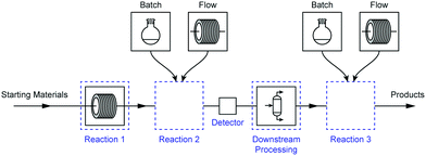
Rather, we must refine our reaction design and problem solving strategies to follow a modular approach where one set of reaction conditions (e.g. batch) can be swapped for another (e.g. flow) without requiring significant changes to either upstream or downstream processes (Fig. 1). It is crucial, therefore, that this process be made as simple as possible to enhance its utility and aid with its adoption by chemists.
As with any union of conceptual ideas, the distinct line that once separated batch and flow becomes blurred. Historically, batch processes were distinctly step-wise operations that required significant manual input from chemists during reaction procedures. Some semi-automated batch platforms, such as the Mettler-Toledo EasyMax system11 and Syrris Atlas HD,12 both sold commercially, were designed to help reduce the labour-consuming manner of batch procedures, yet the overall nature of this synthetic approach has not changed significantly. Conversely, flow procedures were focussed on setting up a reaction sequence, then allowing it to run for extended periods of time in a continuous fashion under steady-state conditions.
The single platform approach therefore enables the modularity of flow processes to be combined with the simplicity of batch, leading to a practical approach to synthesis. Full reaction procedures and associated downstream processes, such as extractions or solvent switching, can be automated, and data from all aspects of an experiment can be collected, displayed, recorded and analysed in real-time.
We believe that we have made a start to overcoming hurdles of batch and flow integration, described below. The approach we have adopted facilitates high temperature, low temperature and high pressure chemistries, control, monitoring, automation and downstream processing – all on a single, unified platform.
Process description
To demonstrate the versatility of this approach, we wanted to select a suitably challenging example involving a number of separate synthesis steps and work-up actions. We therefore chose the preparation of 5-methyl-4-propylthiophene-2-carboxylic acid, an important precursor molecule for the anti-cancer drug candidate AZ82.13 The current synthesis of this molecule,14Fig. 2, involves a number of steps that can best only be carried out in batch-mode while some others can be transitioned into flow, presenting a synthesis opportunity to take advantage of some of the benefits offered by continuous processing techniques. | ||
| Fig. 2 The current synthesis route to 5-methyl-4-propylthiophene-2-carboxylic acid, a precursor to the drug candidate AZ82. | ||
We divided the work into three constituent phases to separate key steps from the others, providing a modular approach to the problems likely to be encountered. Each of these phases was designed to be executed independently of the others, providing freedom in terms of inter-step material transportation and giving flexibility and different opportunities for reactor reconfiguration.
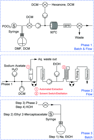
The final experimental schematic, in which the three phases are telescoped together, is shown in Fig. 3. These phases consist of multiple chemical reaction steps (in Phases 1 and 3) and two downstream-processing steps (Phase 2). All equipment was connected to our laboratory network to facilitate automated control and remote monitoring (a more detailed description of this system is given below). This schematic is the result of a number of revisions, typical of any synthesis programme, with changes largely arising from observations during initial experimentation such as unexpected solid formation during Phase 3, differences in solvent boiling points, etc. More information relating to the various revisions and an in-depth description of each phase is provided in the ESI† document.
Integrating batch and flow
Enabling chemists to operate in batch and flow modes on a common reactor platform presented interesting challenges, largely relating to how best to achieve temperature control, reagent addition and product isolation. These issues have been explored in great depth in recent times for flow chemistry,15–17 and are readily accommodated on commercially available equipment. However for batch chemistry similar equipment developments have not progressed as rapidly and are still mainly focussed on manual manipulation at most stages of the process.Design and creation of new glassware
The Vapourtec R4+ system18 is a reactor system capable of heating and cooling flow coils and glass columns using moving gas held at controlled temperatures. In the case of heating, air is passed through a heater coil contained within the bulk of the unit, flowed over the reactor and out an exhaust vent. When cooling, a separate vessel is needed along with a compressed gas line (e.g. nitrogen). The gas stream is passed through this vessel, which is packed with dry ice, where it is cooled, before being sent through an external connector to the reactor. The gas stream then leaves the reactor through the exhaust vent. This device provides a working range of −70 °C to +150 °C on a single platform.For this project however we required new glassware to be developed to support batch reactions. Accordingly, we designed new batch vessels that were compatible with our existing flow equipment (Fig. 4), unlocking a number of advantages that are not possible in standard inexpensive round-bottom flasks (RBF).
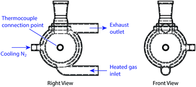 | ||
| Fig. 4 Schematic for the new glassware that was designed to support batch reactions on the R4+ reactor unit. This study uses two flask sizes: 50 mL and 100 mL. | ||
The glassware we developed incorporated a three-layered jacket, with a vacuum between the outer two glass layers. This design greatly enhanced heat transfer from the heating medium (in this case moving gas) to the reaction mixture as the entire inner surface of the flask was maintained at the target temperature, as opposed to just the lower half only, as is typical in RBF reactions. Accordingly we were able to fill the flask to almost its entire volume with reaction liquid. Compared with standard batch procedures there was also enhanced thermal control of the reaction mixture, as the temperature of the glass surface was measured directly by a thermocouple rather than the temperature of a nearby position in a heating block or sand. Furthermore, the exterior surface of the glass remained cool to touch, even if the inner surface exceeded 100 °C. Stirring was achieved through an externally mounted rotating magnetic unit.
In addition to the heated air inlet and exhaust vent, two threaded openings through the vacuum layer were included: one for a thermocouple; and the other to act as the external connector for the cooling nitrogen stream. Adopting such a design enabled the flask to operate throughout the whole R4+ operating temperature range (−70 °C to 150 °C). For this investigation, we used two flasks (50 mL and 100 mL), one of which was cooled only while the other was both heated and cooled. Different sizes and port arrangements can be readily accommodated to give full RBF flexibility. These RBFs can accommodate standard glassware adapters, enabling reflux condensers and other batch apparatus to be connected easily.
Automated control
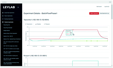
The ability to control and automate reaction procedures can be counted among the benefits of continuous flow procedures. To automate the entire reaction sequence for this investigation, we employed our recently reported control system that enables chemists to monitor and adjust their reactions remotely in real time.19 We felt that this was an element that, while complicating the system, demonstrates a vision for future applications.The system is cloud-based,20,21 with chemist-server and server-equipment interaction occurring via the internet. Each piece of equipment involved with the experiment is connected to an internal laboratory network and has its own unique address where the server can issue commands and receive data. Chemists access the control system through an internet browser, allowing them to monitor and control reactions in real-time from wherever they are located. The system saves all data points to a database, allowing for further analysis at a later date (Fig. 5).
Automation of equipment is achieved through simple scripts defining the logic structures with which the system should base its control strategy. The scripts used for Phases 1, 2 and 3 are included in the ESI.† Using an automated computer-based system made it possible for one researcher to carry out this investigation, greatly simplifying the demand on their time for routine tasks such as extraction and removing the need to manually control the experiment's eight HPLC pumps, two syringe pumps, two peristaltic pumps, four valves and four reactor slots individually.
The use of an automated system also improves reproducibility and robustness, especially in terms of rate of addition into batch vessels. Using a precisely controlled syringe pump to add reagents dropwise into a flask removes the variability that can arise from manual actions.
Continuous extraction and solvent switch
To control the extraction sequence used in Phase 2, we made use of a machine vision system22 we have described previously23–25 that uses open-source technologies to follow the interface boundary between the aqueous and organic phases in a glass separating column. We had previously attempted to use a hydrophobic membrane phase separator, but found that pressure fluctuations downstream of the membrane led to breakthrough (refer to the ESI†).The control scripts for this process, housed on a low-cost Raspberry Pi computer,26 monitored the position of a small coloured float that marked the interface between the aqueous and organic phases (Fig. 6). If the float rose too high as the heavier dichloromethane (DCM) layer increased in volume, a small peristaltic pump was turned on. When the float then fell below a defined lower point, the pump was turned off. This process prevented the under- or over-flow of one phase into the outlet of the other.
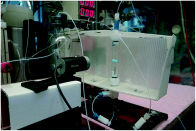 | ||
| Fig. 6 An open-source machine vision system22–25 was used to control the continuous extraction in Phase 2. The low-cost consumer web-camera detected the position of the green coloured float, sending information to a Raspberry Pi device which in turn sent commands to an Arduino board connected to a small peristaltic pump. | ||
The alternative batch process using classical separation funnels are time and labour intensive and do not deliver on scale. They are also subject to the inaccuracies of vision of the experimentalist.
One of the more difficult downstream processing challenges encountered was related to the solvent incompatibility between Phases 1 and 3. Indeed, the main purpose of Phase 2 was to replace the DCM used in Phase 1 with ethanol. While our group has previously reported a spray-drying system27 that can be used to exchange solvents in a wide variety of mixtures, for this project we decided to opt instead for an uncomplicated system that takes advantage of the large difference in boiling points between DCM and ethanol.
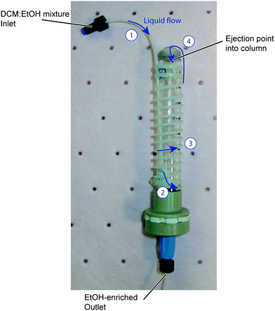
Our simple, single stage distillation unit, shown in Fig. 7, takes as its inlet a solution of reaction mixture in DCM and ethanol. This fluid stream is pumped through PTFE tubing wrapped around a central glass column which is itself placed into a heated jacket slotted into the R4+ unit. The temperature of this jacket is set at 90 °C, significantly above the boiling point of DCM (39.6 °C) and a little above that of ethanol (78.4 °C). As the DCM component of the inlet stream boils, liquid is ejected from the end of the tube into the centre of the column where any remaining DCM boils and is removed by a small nitrogen feed. Owing to the elevated temperature ethanol loss is also experienced, however this did not overly concern us as the solvent is inexpensive and readily available. It is also worth noting that the exiting solvent can be captured and recycled. Periodically a peristaltic pump at the bottom of the column was turned on to reduce the build-up of the product solution (now in ethanol) in the column.
Reaction outcome
Phase 1
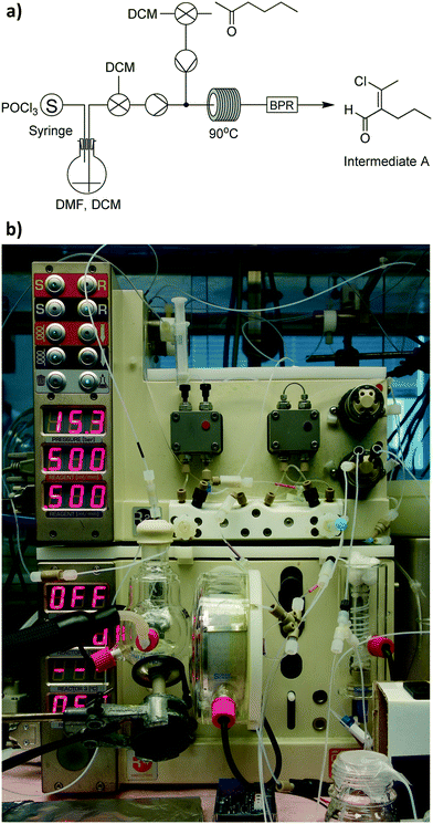
We began our experimentation with Phase 1, which consisted of two individual reaction steps – one batch and one flow (Fig. 8a). For the batch reaction we utilised our smaller 50 mL integrated-batch flask (Fig. 8b), charging it with a mixture of dimethylformamide (DMF) in DCM and cooling it to 0 °C before adding phosphorous oxychloride dropwise. The resulting Vilsmeier–Haack reagent was then pumped from the flask into a flow coil where it reacted with hexanone in DCM to form intermediate A.Owing to the instability of intermediate A on silica, it was not possible to obtain easily an isolated yield with which to determine performance of the process we adopted. However, we were able to obtain a crude NMR yield of approximately 80%, a figure we were satisfied with moving forward into the next phase.
Phase 2
With the crude product mixture from Phase 1 in hand, we turned our attention to Phase 2 (Fig. 9). This reaction phase consisted of two downstream processing procedures, without any reaction steps. A continuous extraction was set up with an aqueous stream of sodium acetate in H2O meeting our product mixture at a tee-piece junction. The resulting biphasic mixture was pumped through a short length of tubing to allow for mixing, before it reached a second tee-piece where it was joined with a stream of DCM. After this process, the mixture was allowed to enter a glass separation column, where the machine vision system described above maintained the position of the interphase boundary within allowable limits. | ||
| Fig. 9 Process schematic for Phase 2. This phase consisted of an automated, continuous liquid–liquid extraction followed by a solvent switch. | ||
Prior to using the distillation column to switch the solvent of the product-containing mixture from DCM to ethanol, we first conducted trials varying fluid flow rates and temperatures with an inlet mixture containing just DCM and ethanol. A table of results from this process is included in the ESI.† The best results were obtained when using a 1![[thin space (1/6-em)]](https://www.rsc.org/images/entities/char_2009.gif) :
:![[thin space (1/6-em)]](https://www.rsc.org/images/entities/char_2009.gif) 1 volumetric ratio of DCM to ethanol and a column temperature of 90 °C, with around 95% removal of DCM (molar basis, the molar fraction of DCM in the exit stream was 2.6%). This corresponds to the azeotrope for the binary ethanol–DCM system.
1 volumetric ratio of DCM to ethanol and a column temperature of 90 °C, with around 95% removal of DCM (molar basis, the molar fraction of DCM in the exit stream was 2.6%). This corresponds to the azeotrope for the binary ethanol–DCM system.
Having identified operating conditions for our distillation process, we used it successfully to exchange the solvent of the organic layer collected from the extraction column. The resulting ethanol-enriched stream was pumped through a small plug of anhydrous magnesium sulfate to remove any water contained with the stream.
Phase 3
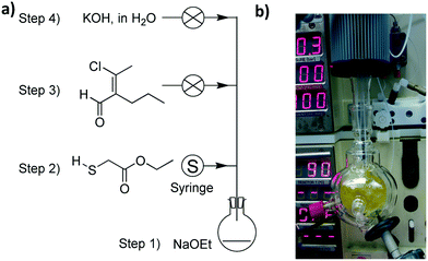
The last phase of the reaction consisted of four reaction steps (Fig. 10a), all of which were conducted in batch mode. For this process we used the 100 mL integrated-batch flask with an ambient-cooled condenser connected to the top (a gaseous nitrogen stream was passed over the fins to aid with cooling when under reflux conditions, Fig. 10b). This condenser was sealed and purged with a nitrogen line to ensure that the sequence of reactions in Phase 3 was kept under an inert atmosphere.Initially we added sodium to a room temperature solution of ethanol in the flask to generate the corresponding ethoxide. This first step was carried out manually, while the remaining three steps were automated using our control system. The second step involved adding ethyl 2-mercaptoacetate dropwise by a syringe pump to the sodium ethoxide solution at 0 °C, then allowing the mixture to warm to room temperature. Subsequently the product mixture from Phase 2 was added dropwise and stirred at reflux, before an aqueous solution of potassium hydroxide was added dropwise.
Following a manual workup procedure involving ethanol removal and acidification with HCl, 5-methyl-4-propylthiophene-2-carboxylic acid was isolated using flash chromatography.
Process telescoping
The final step of our investigation was to attempt Phases 1, 2 and 3 in a fully telescoped manner, where each phase was run continuously into the next under the control of our automated computer system. The equipment layout in this scenario is shown earlier, in Fig. 3. To achieve this, we needed to change two things: firstly, we connected the output from the flow coil in Phase 1 to a bidirectional valve which either diverted the outlet flow to waste (at the beginning of the flow reaction) or allowed it to flow directly into Phase 2 (when the product mixture just reached the end of the flow coil); and secondly, we added an elevated, N2 purged reservoir to the end of Phase 2 to hold our ethanol-rich mixture above the reaction flask for Phase 3 (gravity was used to add this mixture dropwise into the reaction flask when a valve was opened).Having set up our equipment to handle telescoping of the three phases, we carried out the experiment successfully. One researcher was sufficient to manage the entire process, and it was possible to obtain our desired carboxylic acid product with an overall yield of 30%, slightly above the 27% overall yield obtained when the reactions are carried out manually in typical batch mode using standard procedures.
Closing remarks
We have successfully integrated batch and flow reactions on a single reactor platform, using an automated control system to facilitate the entire process. By adopting this approach, a chemist was able to oversee the preparation of 5-methyl-4-propylthiophene-2-carboxylic acid which consisted of multiple reaction steps and two downstream processing steps. We also telescoped each step of this process into the others, further reducing the demand on the researcher's time.Much of the experimental detail typically reported above is often relegated to ESI† or worse assumed to be common knowledge by those skilled in the art of synthesis. In fact, this is just the area where lack of robustness or imprecise reporting of details leads to scale-up errors and lack of reproducibility.
We believe the integration of this kind represents the beginnings of a general shift in synthetic techniques, whereby any element of batch and flow can be conducted on the same working reactor platform thus creating a new environment for synthesis. The general concepts demonstrated are adaptable to any chemistry environment without the need for any special or expensive equipment.
What has been presented represents some opportunities for a co-ordinated system illustrated by a single example which incorporated a number of synthesis protocols. In reality, any one operation could have been conducted in isolation on this universal modular reactor platform.
Acknowledgements
The authors would like to acknowledge Dr. Nikzad Nikbin and Dr. Richard Ingham for their input into the design of the integrated batch flasks. We are also grateful to the Woolf Fisher Trust (D. E. F.) and the EPSRC (S. V. L., grant codes EP/K009494/1, EP/M004120/1 and EP/K039520/1) for financial assistance.References
- M. Baumann and I. R. Baxendale, Beilstein J. Org. Chem., 2015, 11, 1194–1219 CrossRef CAS PubMed.
- V. Sans and L. Cronin, Chem. Soc. Rev., 2016, 45, 2032–2043 RSC.
- G. Whitesides, Angew. Chem., Int. Ed., 2015, 54, 3196–3209 CrossRef CAS PubMed.
- D. E. Fitzpatrick, C. Battilocchio and S. V. Ley, ACS Cent. Sci., 2016, 2, 131–138 CrossRef CAS PubMed.
- A. Adamo, R. L. Beingessner, M. Behnam, J. Chen, T. F. Jamison, K. F. Jensen, J.-C. M. Monbaliu, A. S. Myerson, E. M. Revalor, D. R. Snead, T. Stelzer, N. Weeranoppanant, S. Y. Wong and P. Zhang, Science, 2016, 352, 61–67 CrossRef CAS PubMed.
- K. F. Jensen, B. J. Reizman and S. G. Newman, Lab Chip, 2014, 14, 3206–3212 RSC.
- N. M. Roda, D. N. Tran, C. Battilocchio, R. Labes, R. J. Ingham, J. M. Hawkins and S. V. Ley, Org. Biomol. Chem., 2015, 13, 2550–2554 CAS.
- N. H. Park, T. J. Senter and S. L. Buchwald, Angew. Chem., Int. Ed., 2016, 55, 11907–11911 CrossRef CAS PubMed.
- J.-S. Poh, S.-H. Lau, I. G. Dykes, D. N. Tran, C. Battilocchio and S. V. Ley, Chem. Sci., 2016 10.1039/C6SC02581A , Advance Article.
- C. Battilocchio, F. Feist, A. Hafner, M. Simon, D. N. Tran, D. M. Allwood, D. C. Blakemore and S. V. Ley, Nat. Chem., 2016, 8, 360–367 CrossRef CAS PubMed.
- For more information about this system, visit http://www.mt.com/gb/en/home/products/L1_AutochemProducts/Chemical-Synthesis-and-Process-Development-Lab-Reactors/Synthesis-Reactor-Systems/EasyMax-Synthesis-Reactor.html, Accessed 31 August 2016.
- For more information about the system, visit http://syrris.com/batch-products/atlas-hd-overview, Accessed 31 August 2016.
- J. Wu, K. Mikule, W. Wang, N. Su, P. Petteruti, F. Gharahdaghi, E. Code, X. Zhu, K. Jacques, Z. Lai, B. Yang, M. L. Lamb, C. Chuaqui, N. Keen and H. Chen, ACS Chem. Biol., 2013, 8, 2201–2208 CrossRef CAS PubMed.
- M. Bolli, D. Lehmann, B. Mathys, C. Mueller, O. Nayler, B. Steiner and J. Velker, WIPO Pat., WO2007080542A1, 2007 Search PubMed.
- S. V. Ley, D. E. Fitzpatrick, R. J. Ingham and R. M. Myers, Angew. Chem., Int. Ed., 2015, 54, 3449–3464 CrossRef CAS PubMed.
- S. V. Ley, D. E. Fitzpatrick, R. M. Myers, C. Battilocchio and R. J. Ingham, Angew. Chem., Int. Ed., 2015, 54, 10122–10136 CrossRef CAS PubMed.
- R. M. Myers, D. E. Fitzpatrick, R. M. Turner and S. V. Ley, Chem. – Eur. J., 2014, 20, 12348–12366 CrossRef CAS PubMed.
- For more information about this system, visit https://www.vapourtec.com/products/r-series-flow-chemistry-reactor-heater-cooler/, Accessed 31 August 2016.
- D. E. Fitzpatrick, C. Battilocchio and S. V. Ley, Org. Process Res. Dev., 2016, 20, 386–394 CrossRef CAS.
- S. V. Ley, D. E. Fitzpatrick, R. J. Ingham and N. Nikbin, Beilstein Magazine, 2015, 1, No. 2 Search PubMed.
- Other cloud based chemistry systems include ChemInventory, https://www.cheminventory.net/, Accessed 31 August 2016.
- M. O'Brien and D. Cooper, Synlett, 2016, 27, 164–168 CrossRef.
- S. V. Ley, R. J. Ingham, M. O'Brien and D. L. Browne, Beilstein J. Org. Chem., 2013, 9, 1051–1072 CrossRef CAS PubMed.
- D. X. Hu, M. O'Brien and S. V. Ley, Org. Lett., 2012, 14, 4246–4249 CrossRef CAS PubMed.
- M. O'Brien, P. Koos, D. L. Browne and S. V. Ley, Org. Biomol. Chem., 2012, 10, 7031–7036 Search PubMed.
- For more information about the Raspberry Pi, refer to https://www.raspberrypi.org/, Accessed 31 August 2016.
- B. J. Deadman, C. Battilocchio, E. Sliwinski and S. V. Ley, Green Chem., 2013, 15, 2050–2055 RSC.
Footnote |
| † Electronic supplementary information (ESI) available. See DOI: 10.1039/c6re00160b |
| This journal is © The Royal Society of Chemistry 2016 |

