TiO2 cement for high-performance dye-sensitized solar cells†
Yu Hou‡
ab,
Shuang Yang‡a,
Chunzhong Lia,
Huijun Zhaob and
Hua Gui Yang*a
aKey Laboratory for Ultrafine Materials of Ministry of Education, School of Materials Science and Engineering, East China University of Science and Technology, 130 Meilong Road, Shanghai, 200237, China. E-mail: hgyang@ecust.edu.cn
bCentre for Clean Environment and Energy, Griffith University, Gold Coast Campus, Queensland 4222, Australia
First published on 30th August 2016
Abstract
This paper reports a novel method to prepare uniform and stable TiO2 films via a cementing technique. To consolidate the mesoporous films composed of TiO2 particles, which acted as aggregates, metastable anatase TiO2 nanomaterials were employed as cement. After heat treatment, the cement materials can change into a stable sticking substance between the TiO2 particles. Also, during the additive evaporating of TiO2 pastes, the cement can suppress the spatial contraction and facilitate the formation of mesoporous films. An energy conversion efficiency of 8.31% was reached by using the cemented photoanode for dye-sensitized solar cells (DSCs), attaining 31.1% improvement compared to the pristine sample. Our experimental results further confirm that the cementing method can not only favor the film formation, and reinforce the porous structure, but also enables improved dye adsorption and light harvesting ability in DSCs.
1. Introduction
As one of the most important and revolutionary construction materials, concrete has been widely used due to its low-cost, durability and mechanical tenability since the mid-18th century.1,2 It is mainly composed of a coarse granular material (aggregate) embedded in a hard matrix of material (cement) which fills the space among the aggregate particles and glues them together. Despite the success of concrete in building, it would be highly desirable to extend the concept of “concrete” into nanoscale materials, which also holds promise for solving some practical issues. With the growing global requirement for clean energy, the generation of electrical power from solar energy conversion has attracted considerable attention in recent years. Among various photovoltaic devices, dye-sensitized solar cells (DSCs) have been investigated extensively in light of their prospects of high efficiency, their ease of fabrication and potential for low-cost manufacture.3–6 Nanocrystalline TiO2 (ca. 20 nm in diameter) films with a high accessible surface area, which ensures large amount of dye molecules loading, has been the general photoanode for developing high-performance DSCs.7–11 However, the major hurdles for the attainment of higher energy conversion efficiencies for TiO2-based photoanodes lie in the potential drop in the regeneration process and the recombination loss between electrons in the sintered TiO2 nanoparticle networks.10,12 One critical reason is the weak connection of the nanoparticles and the mass grain boundaries usually act as the sites of electron traps.13–15 However, the presence of cement among the TiO2 nanoparticles, forming stable cemented networks, which is a homogeneous porous material, may provide a feasible approach toward these problems. The strong adhesion between particles of such structures may provide a possible approach for the optimization of electron pathway and it is expected from the point of photogenerated carriers to the collecting electrode would significantly improve the energy conversion efficiency.16The optimal cement in such system is made up of metastable TiO2 materials to ensure its coherence of materials and photoelectric properties. In particular, TiO2 crystals with clean {001} facets, which have been evidenced to be unstable and usually tends to reconstruct, are appropriate in such system.17,18 Another reason is that the {001} faceted TiO2 tend to be spontaneously attached to the aggregates and further cement them as a result of its unique surface structural characteristics.18–20
Herein, we have employed the metastable anatase TiO2 nanomaterials as cement and the TiO2 nanoparticles as aggregates that the porous concrete of stable nanoparticles can be obtained as photoanode after heat treatment. Interestingly, we found the metastable anatase TiO2 nanosheets disappeared after heat treatment and ultrathin stacking substance can be observed coated on the particle surface uniformly. In the cementing system, the TiO2 particles which act as the backbone of the electrode, and more importantly, the cement can provide considerable adhesion stress and toughness between the aggregates. As a result, such cemented structure not only exhibits high specific surface area, but also has firm connection between each nanoparticle which can provide rapid electron transfer pathway and enhance the stability of photoanode. Indeed, DSCs based on these photoanodes have yielded much improved energy conversion efficiency compared to solar cells with the standard TiO2 photoanodes.
2. Experimental
2.1 Synthesis of metastable anatase TiO2 nanomaterials
Anatase TiO2 nanosheets with a high percentage of {001} facets was prepared through a simple hydrothermal method by using tetrabutyl titanate (Ti(OBu)4, 98%, Aldrich) as Ti source and hydrofluoric acid (HF, 48%, Sigma-Aldrich) as capping agent. All of the chemicals were used without further purification. Caution: hydrofluoric acid (HF) is extremely corrosive and toxic and it should be handled with extreme care! For a typical experiment, 5 mL of Ti(OBu)4 and 0.6 mL of HF were added drop-wise into a dried Teflon-lined stainless autoclave with a capacity of 50 mL. Then, the autoclave was sealed and heated at 180 °C for 24 h in an electric oven. After completion of the reaction, the autoclave was taken out and cooled to room temperature. The product was collected by washing the precipitate thoroughly with absolute ethanol and deionized water for three times to remove the residual contamination.2.2 Fabrication of DSCs
To fabricate the nanoporous photoanode, the viscous pastes were prepared according to the literature with different weigh ratios of the metastable TiO2 nanosheets to P25 nanoparticles. The sample with the nanosheets of 5%, 10% and 15% is numbered to be sample C1, C2 and C3, respectively. To prepare the screen-printing paste, terpineol and ethyl cellulose were added into the ethanol solution of TiO2 nanosheets and P25 nanoparticles followed by sonication and stirring.21 A 12 μm-thick layer of the as-prepared TiO2 particles and 4 μm-thick scattering layer of 200 nm-sized TiO2 particles (HEPTACHROMA, DHS-NanoT200) was loaded on the fluorine doped SnO2 (FTO) conducting glass (NSG, 8 Ω per square) by screen printing technique before sintering at 500 °C. After cooling to 80 °C, the TiO2 film was immersed in a 5 × 10⁻⁴ M solution of N719 dye (Solaronix SA, Switzerland) in acetonitrile/tert-butyl alcohol (V/V = 1/1) for 24 h. The Pt-electrode was prepared by drop-casting 0.5 mM H2PtCl6/ethanol solution on the clean FTO conductive glass and subsequently sintering the obtained Pt coated FTO glass in a muffle furnace at 450 °C for 30 min. DSCs were assembled together with the dye-sensitized TiO2 electrode and the Pt electrode by a 25 μm thick hot-melt film (Surlyn 1702, DuPont) and sealed up by heating. The cell internal space was filled with electrolytes using a vacuum pump. The liquid electrolyte was composed of 0.60 M 1-butyl-3-methylimidazolium iodide, 0.03 M I2, 0.50 M 4-tert-butyl pyridine, and 0.10 M guanidinium thiocyanate with acetonitrile as the solvent. The sealed DSCs with an active area of 0.25 cm2 were used for the photocurrent–voltage test.2.3 Characterization
The morphology and structure of the samples were characterized by atomic force microscopy (AFM, Veeco, USA, tapping mode), high-resolution transmission electron microscopy (HRTEM, JEOL JEM-2010F, F20, 200 kV), field emission scanning electron microscopy (FESEM, HITACHI S4800) and X-ray diffraction (XRD, Bruker D8 Advanced Diffractometer, Cu Kα radiation, 40 kV). The current–voltage tests of DSCs were performed under one sun condition using a solar light simulator (Oriel, 91160, AM 1.5 globe). The power of the simulated light was calibrated to 100 mW cm−2 using a Newport Oriel PV reference cell system (model 91150 V). The EIS experiments were measured in the dark using an electrochemical workstation (Parstat 2273, Princeton). The frequency range of EIS experiments was from 100 kHz to 100 mHz with an AC modulation signal of 10 mV and bias DC voltage of 0.60 V. The curves were fitted by the Zview software. The amount of adsorbed dye was measured by desorbing the dye into 10 mM NaOH solution and measuring the absorption peak intensity of N719 at 515 nm with a Cary 500 Spectrophotometer. The diffuse-reflectance spectra were measured by using a Cary 500 Spectrophotometer.3. Results and discussion
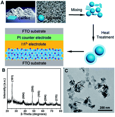
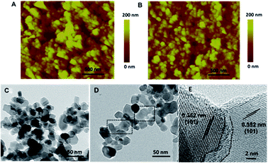
As shown in Fig. 1A, we first employ metastable anatase TiO2 nanosheets as cement, which is readily changed and have high surface activity, and P25 nanoparticles as the aggregate and further mixed within the solvents. In principle, the ratio between the cement and aggregate is an important parameter to determine the properties of the porous concretes. We prepared the samples with cements of 5, 10 and 15 wt% which are numbered to be C1, C2 and C3, respectively. In this work, the synthetic method of anatase TiO2 is based on the one-pot hydrothermal synthesis with approximately 80% {001} facets.17 X-ray diffraction (XRD) and transmission electron microscope (TEM) were employed to confirm the crystal structure and morphology of the as-prepared TiO2 sample. Fig. 1B shows the typical XRD pattern of the resulting product, and the diffraction peaks with 2θ = 25.3°, 37.8° and 48.1° can be indexed to (101), (004), and (200) crystal planes of anatase TiO2 (tetragonal, I41/amd, JCPDS 21-1272), respectively, indicating its pure anatase TiO2 phase. Fig. 1C presents the TEM image of the product, which reveals the uniform, well-defined sheet-shaped structures of the obtained TiO2 products. Statistically, the anatase TiO2 nanosheets have a side length of 40 nm and a thickness of 4 nm on the average.To reveal the morphological information of the as-prepared films of the sintered pure nanoparticles and cemented TiO2 nanoparticles, atomic force microscopy (AFM) imaging analysis was performed (Fig. 2A and B). The images were recorded in the tapping mode using a Dimension Icon scanning probe microscope. Clearly, both the blank P25 and C3 films show uniform morphologies with similar particle size. In contrast, submicron sized pores, whose diameter even larger than 500 nm, can be found on the P25 films which may result in a loose and weak connection. It has been known that additives such as alcohols and cellulous, must be incorporated to increase the viscosity of the screen-printing pastes. Nevertheless, this must be removed by an annealing procedure that the film usually undergoes drastic contraction. The submicron sized pores here may be stemmed from the contraction, cracking or collapse during the annealing process. As comparison, the C3 film exhibits a very uniform morphology with a root-mean-square roughness (Rq) of 37.74 nm and an average surface roughness (Ra) of 28.82 nm, which were obtained by analysing selected line scans across the topology of the C3 film surface (Fig. S1†).
After the sintering procedure, samples were removed from glass substrate, grinded, ultrasonicated and then deposited on the transmission electron microscope (TEM) grid. Intriguingly, we found the cemented samples are difficult to be dispersed in ethanol. Under an ultrasound treatment for 10 min, the pure P25 sample become turbid, however, the cemented TiO2 sample is still clear while the sintered particles sink to the bottom (Fig. S2†). This indicates that the cemented nanoporous network is quite firm and stable which is hard to be destroyed in accordance with the AFM results. Fig. 2C represents the typical TEM image of the sintered P25 sample, all the nanoparticles show clear outline and well-defined edges. In comparison, as shown in Fig. 2D, the surface of the crystals became rough and unclear with the aid of cementing process. Curiously, the sheet shaped TiO2 crystals can not be observed and instead, as shown in the dotted circles, crystal boundaries become ambiguous and the particles seemed to be integrated which suggests the variation of the metastable TiO2 nanomaterials on the surface of the nanoparticles. High-resolution transmission electron microscope (HR-TEM) images (Fig. 2E) further reveal that the typical interfacial junction between two particles, which derived from the cement, is normally amorphous layers and the particles are well crystallized with a d-spacing of 0.352 nm well matched to the d101 lattice. On the basis of above observation, we can reasonably conclude the merits of the cementing process for film formation process: (1) have no crack, contraction, or collapse with a very uniform morphology; (2) more compact and firm due to the cementing effect.
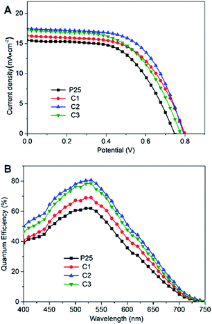
To confirm the performance of the cemented mesoscopic TiO2 photoanode, all samples were used to prepare the photoanode and then fabricate DSCs by an identical process (Table 1). With relatively small short-circuit current density (Jsc, 14.90 mA cm−2) and fill factor (FF, 56.8%), the cell based on P25 presented an energy conversion efficiency (η) of 6.34%. In mesoporous films, electron diffusion is determined by trapping/detrapping events along the sites of the electron traps that generally at TiO2 surface and of significant importance at the interface between TiO2 nanoparticles.14 Therefore, electron transfer in the P25 film should be limited by the resistive loss of the weak connection between the particles which result in low Jsc values.
| DSCs | Cement content [wt%] | Dye-loading [10−7 mol cm−2] | Jsc [mA cm−2] | Voc [mV] | FF [%] | η [%] |
|---|---|---|---|---|---|---|
| a The active areas of the photoelectrodes were all 0.25 cm2 with similar film thickness. | ||||||
| P25 | 0 | 1.19 | 14.90 | 750 | 56.8 | 6.34 |
| C1 | 5 | 1.30 | 16.10 | 800 | 57.8 | 7.45 |
| C2 | 10 | 1.41 | 17.25 | 790 | 60.9 | 8.31 |
| C3 | 15 | 1.45 | 17.00 | 775 | 56.9 | 7.49 |
With the increased dye loadings in cemented films, all the key parameters of DSCs based on C1 photoanode improved (Jsc, 16.10 mA cm−2, Voc, 800 mV; FF, 57.8%), yielding a η of 7.45%. Encouragingly, the performance of C2 was further improved with a η of 8.31%. With further addition of cements, DSCs based on C3 give lower Jsc and η which can be explained that the excess of the amorphous coating may reversely hamper the electron flow. The higher Voc of the DSCs based on cemented films may be as a consequence of reduced charge recombination rate due to the firm adhesion between the particles within the inner network, which results in an increase in electron density in TiO2 films, and further the shift of the quasi-Fermi level.22 It has been reported that the FF is generally related to the internal resistance of the devices.23 The cell based on C2 electrode exhibits the highest FF of 60.9%, indicating its lowest internal resistance, which might be provoked by the low electron transport resistance and charge recombination rate of the cemented electrode film.
Fig. 3B depicts the incident-photon-to-current efficiency (IPCE) spectra of the DSCs based on the cemented films and P25 electrodes. The integrated current densities for DSCs based on P25, C1, C2 and C3 photoanodes were 14.67, 16.03, 17.14 and 16.86 mA cm−2, respectively, in good agreement with the similar measured Jsc. The improvement can be ascribed to the enhanced electron injection and charge-transfer efficiency as well as the slightly higher amount of dye loading (Table 1). It has been reported that, however, when the dye uptake increases, the IPCE only increased slightly,24–26 and thus, we can presume that the intrinsic increases in the photocurrent and IPCE are primarily related to the enhanced electron injection and low resistive losses of the cemented structures.
 | ||
| Fig. 3 (A) J–V curves and (B) IPCE spectra of DSCs fabricated from P25, C1, C2 and C3 photoanodes, respectively. | ||
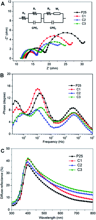
To demonstrate the above inferences, electrochemical impedance spectra (EIS) was employed to explore the electron transport property of DSCs based on P25, C1, C2 and C3 photoanodes as depicted in Fig. 4A. An equivalent circuit (the inset in Fig. 4A) was given to fit the series resistance (Rs), charge-transfer resistance (R1, R2, and Ws) and the corresponding constant phase angle element (CPE) in DSCs.27–31 It is generally accepted that the series resistance (Rs) is mainly related to resistance of FTO glass substrate, contact resistance, counter electrode material and the resistance of external circuits, etc. Although the substrate is identical, there is obvious difference of Rs between P25 and the cemented samples. The tight adhesion between the cemented photoanode and the FTO substrate should be responsible for their lower Rs. The semicircle in the high frequency region (R1) corresponds to the interfacial resistance of the Pt/FTO substrate and redox reaction of I−/I3− at the values related to the identical FTO substrate, Pt counter electrode and external circuits. The semicircle in the intermediate frequency semicircle (R2) represents the dye-absorbed TiO2/electrolyte interface and charge transport resistance in the TiO2 film. Herein, the values of R2 vary in the consequence of P25 (9.36 Ω) > C1 (8.37 Ω) > C3 (5.77 Ω) > C2 (4.66 Ω) which verifies the considerable reduction of electrical resistance of the cemented photoanode. Nevertheless, the C3 electrode exhibits a larger R2 than C2 which suggests that an excess of cement would reversely impede the electron flow. Combining with the photovoltaic results, we deduce that the firm adhesion between the anode/FTO substrate interface as well as the interparticles would reduce the internal resistance significantly in agreement with the Jsc and FF values.
Complementary to the Nyquist results, Bode plots in Fig. 4B further confirm that the characteristic medium-frequency peak of the devices firstly shifts to lower frequency and then rebound with the incorporating of cement. This indicates, in the cemented photoanode within appropriate amount of cement, a longer electron lifetime can be reached and the excess of cement may hinder the charger transport in consistent with the above results. Fig. 4C displays the diffuse reflectance spectra of the films based on P25, C1, C2 and C3, all films represent high diffuse reflection in the range from 380 to 450 nm. In contrast to P25 film, the other three films, with increasing concentrations of cements from C1 to C3, show improved light-scattering capabilities both in the visible and near-infrared regions. We deduce that light is difficult to propagate through the compact cemented films and thus can be localized and trapped significantly. Therefore, the improved light scattering capacity of the cemented structure is proportional to the slightly higher Jsc for the cemented electrode compared to the P25 electrode.
4. Conclusions
In summary, with the aid of metastable anatase TiO2 nanomaterials as the cements, we have successfully implanted the “concrete” into the mesoscopic photoanode of DSCs to fabricate stable and uniform mesoporous films. It was found that the cementing technique was favourable for the film formation and reinforce the porous structure significantly which resulted in an impressive energy conversion efficiency of 8.31%, attaining 31.1% improvement than the standard sample in DSCs. Our further characterization illustrated that the cemented structure can provide both tight connection between nanoparticles and enhanced light-scatting ability which resulted in reduced resistive losses and superior light capture capacity. In addition, the method of cementing mesoscopic TiO2 films may open up an alternative avenue for the development of high-performance photovoltaic devices including dye-sensitized solar cells and perovskite-based hybrid solid-state solar cells.Acknowledgements
This work was financially supported by National Natural Science Foundation of China (21373083, 21573068 and 51602103), SRF for ROCS, SEM, SRFDP, Fundamental Research Funds for the Central Universities (WD1514301), China Postdoctoral Science Foundation Funded Project (2015M581547, 2016T90342), “Chen Guang” Project supported by Shanghai Municipal Education Commission and Shanghai Education Development Foundation (15CG26), the Major Research plan of the National Natural Science Foundation of China (91534202), 111 Project (B14018), Shanghai Sailing Program (16YF1402100) and ARC Discovery Projects (DP150103775).Notes and references
- F. M. Lea, The chemistry of cement and concrete, Edward Arnold, London, 3rd edn, 1970 Search PubMed.
- P. K. Mehta, Concrete: Structure, Properties, and Materials, Prentice Hall, Englewood Cliffs, New Jersey, 1986 Search PubMed.
- B. O'regan and M. Grätzel, Nature, 1991, 353, 737–740 CrossRef.
- Y. Hou, D. Wang, X. H. Yang, W. Q. Fang, B. Zhang, H. F. Wang, G. Z. Lu, P. Hu, H. J. Zhao and H. G. Yang, Nat. Commun., 2013, 4, 1583 CrossRef PubMed.
- M. Adachi, Y. Murata, J. Takao, J. Jiu, M. Sakamoto and F. Wang, J. Am. Chem. Soc., 2004, 126, 14943–14949 CrossRef CAS PubMed.
- X. Kang, C. Jia, Z. Wan, J. Zhuang and J. Feng, RSC Adv., 2015, 5, 16678–16683 RSC.
- M. Ye, D. Zheng, M. Lv, C. Chen, C. Lin and Z. Lin, Adv. Mater., 2013, 25, 3039–3044 CrossRef CAS PubMed.
- Z. Sun, J. H. Kim, Y. Zhao, D. Attard and S. X. Dou, Chem. Commun., 2013, 49, 966–968 RSC.
- J. Kim, J. K. Koh, B. Kim, J. H. Kim and E. Kim, Angew. Chem., Int. Ed., 2012, 51, 6864–6869 CrossRef CAS PubMed.
- A. Hagfeldt, G. Boschloo, L. Sun, L. Kloo and H. Pettersson, Chem. Rev., 2010, 110, 6595–6663 CrossRef CAS PubMed.
- D. Chen, F. Huang, Y. B. Cheng and R. A. Caruso, Adv. Mater., 2009, 21, 2206–2210 CrossRef CAS.
- J. Navas, E. Guillén, R. Alcántara, C. Fernández-Lorenzo, J. Martín-Calleja, G. Oskam, J. Idígoras, T. Berger and J. A. Anta, J. Phys. Chem. Lett., 2011, 2, 1045–1050 CrossRef CAS.
- M. A. Henderson, Surf. Sci. Rep., 2011, 66, 185–297 CrossRef CAS.
- S. H. Kang, S. H. Choi, M. S. Kang, J. Y. Kim, H. S. Kim, T. Hyeon and Y. E. Sung, Adv. Mater., 2008, 20, 54–58 CrossRef CAS.
- X. Chen, L. Tang, S. Yang, Y. Hou and H. G. Yang, J. Mater. Chem. A, 2016, 4, 6521–6526 CAS.
- M. A. Rafiee, T. N. Narayanan, D. P. Hashim, N. Sakhavand, R. Shahsavari, R. Vajtai and P. M. Ajayan, Adv. Funct. Mater., 2013, 23, 5624–5630 CrossRef CAS.
- X. H. Yang, Z. Li, C. Sun, H. G. Yang and C. Li, Chem. Mater., 2011, 23, 3486–3494 CrossRef CAS.
- S. Yang, Y. Hou, B. Zhang, X. H. Yang, W. Q. Fang, H. J. Zhao and H. G. Yang, J. Mater. Chem. A, 2013, 1, 1374–1379 CAS.
- H. B. Jiang, Q. Cuan, C. Z. Wen, J. Xing, D. Wu, X. Q. Gong, C. Li and H. G. Yang, Angew. Chem., Int. Ed., 2011, 123, 3848–3852 CrossRef.
- X. Wu, Z. Chen, G. Q. Lu and L. Wang, Adv. Funct. Mater., 2011, 21, 4167–4172 CrossRef CAS.
- S. Ito, T. N. Murakami, P. Comte, P. Liska, C. Grätzel, M. K. Nazeeruddin and M. Grätzel, Thin Solid Films, 2008, 516, 4613–4619 CrossRef CAS.
- B. Tan and Y. Wu, J. Phys. Chem. B, 2006, 110, 15932–15938 CrossRef CAS PubMed.
- M. Grätzel, Nature, 2001, 414, 338–344 CrossRef PubMed.
- W. Yang, Y. Wang and W. Shi, CrystEngComm, 2012, 14, 230–234 RSC.
- T. Ma, K. Inoue, K. Yao, H. Noma, T. Shuji, E. Abe, J. Yu, X. Wang and B. Zhang, J. Electroanal. Chem., 2002, 537, 31–38 CrossRef CAS.
- T. Ma, M. Akiyama, E. Abe and I. Imai, Nano Lett., 2005, 5, 2543–2547 CrossRef CAS PubMed.
- Q. Wang, J. E. Moser and M. Grätzel, J. Phys. Chem. B, 2005, 109, 14945–14953 CrossRef CAS PubMed.
- J.-C. Lin, C.-P. Lee and K.-C. Ho, J. Mater. Chem., 2012, 22, 1270–1273 RSC.
- Y. Liu, J. R. Jennings, Y. Huang, Q. Wang, S. M. Zakeeruddin and M. Grätzel, J. Phys. Chem. C, 2011, 115, 18847–18855 CAS.
- K.-M. Lee, V. Suryanarayanan and K.-C. Ho, Sol. Energy Mater. Sol. Cells, 2007, 91, 1416–1420 CrossRef CAS.
- Z. He, H. Phan, J. Liu, T.-Q. Nguyen and T. T. Y. Tan, Adv. Mater., 2013, 25, 6900–6904 CrossRef CAS PubMed.
Footnotes |
| † Electronic supplementary information (ESI) available: AFM image and UV-vis spectra are shown in supplementary information. See DOI: 10.1039/c6ra20039g |
| ‡ These authors contributed equally to this work. |
| This journal is © The Royal Society of Chemistry 2016 |


