DOI:
10.1039/C6RA09385J
(Paper)
RSC Adv., 2016,
6, 51435-51445
Novel bis- and tris-cyclometalated iridium(III) complexes bearing a benzoyl group on each fluorinated 2-phenylpyridinate ligand aimed at development of blue phosphorescent materials for OLED†
Received
12th April 2016
, Accepted 10th May 2016
First published on 11th May 2016
Abstract
Novel bis- and tris-cyclometalated iridium(III) complexes bearing a benzoyl group on each fluorinated 2-phenylpyridinate ligand were developed, aimed at the development of blue phosphorescent materials for organic light-emitting diodes (OLED). When acetylacetonate (acac) was employed as an ancillary ligand, the emission wavelength (λPL) of the 5′-benzoylated bis-cyclometalated complex was blue-shifted up to 479 nm (in dichloromethane at rt, emitting bluish green) in combination with fluorine substituents. Ancillary ligand replacement in the 2-(5-benzoyl-4,6-difluorophenyl)pyridinate-based bis-cyclometalated complex from acac to picolinate gave rise to a further blue shift of λPL to 464 nm, and sky-blue emission was observed. The 2-(5-benzoyl-4,6-difluorophenyl)pyridinate-based homoleptic tris-cyclometalated complex exhibited a more blue-shifted λPL at 463 nm than any other bis- and tris-cyclometalated complexes developed here, emitting sky blue with a photoluminescence quantum yield of 0.90 (in dichloromethane at rt). Using this sky-blue phosphorescent tris-cyclometalated complex as an emitting dopant, a poly(9-vinylcarbazole)-based OLED was fabricated, and excellent blue emission with a Commission Internationale de L'éclairage (CIE) chromaticity coordinate of (0.16, 0.28) was observed, where an external quantum efficiency (ηext) of 1.81% was obtained. The OLED performance was drastically improved by using a solution-processed double-emitting layer device structure, and ηexts of 8.55 and 7.46% were achieved for the present sky-blue phosphorescent bis- and tris-cyclometalated iridium(III) complexes, respectively (CIE chromaticity coordinates: (0.17, 0.33) and (0.17, 0.29), respectively).
1. Introduction
From the viewpoint of the development of highly efficient organic light-emitting diodes (OLED), electrophosphorescent devices have been attracting considerable attention for the last decade1–3 because they utilize both singlet and triplet excitons to achieve as high as 100% internal quantum efficiency, four times larger than that of electrofluorescent devices.4 As phosphorescent materials for OLED applications, organometallic complexes with a heavy metal center are reliable candidates, and organoiridium and organoplatinum complexes have been intensively developed, as demonstrated by the pioneering works of Thompson and coworkers,5–8 because the strong spin–orbit coupling caused by the organometallic frameworks facilitates the intersystem crossing from the singlet state to the triplet.11 Especially, bis- and tris-cyclometalated iridium(III) complexes represented by (C^N)2Ir(LX) and (C^N)3Ir (C^N, 2-phenylpyridinate-type cyclometalated ligand; LX, anionic ancillary ligand), respectively, show efficient phosphorescence with relatively high photoluminescence (PL) quantum yields, and their emission color is easily tuned by the well-designed C^N ligand.1,5,6,8–10 Although blue phosphorescent cyclometalated iridium(III) complexes are important as RGB emitters in the fabrication of OLED-based electric devices, such as full color displays1,3 and mercury-less illumination apparatuses,3,12–14 they are less frequently reported in comparison with green and red phosphorescent emitters.1,15–18 This is mainly because the structural variation of the C^N ligand to achieve the high-lying triplet level is considerably limited.
In the case of (C^N)2Ir(LX) and (C^N)3Ir, it is well known that the introduction of electron-withdrawing substituents, such as fluorine and trifluoromethyl, gives rise to stabilization of the highest occupied molecular orbital (HOMO) to yield a wide HOMO–LUMO energy gap (LUMO; lowest unoccupied molecular orbital), as a result, achieving the high-lying triplet level.1,19–21 For example, employing 2-(2,4-difluorophenyl)pyridinate leads to sky-blue emission in combination with a picolinate ancillary ligand.9,19,22 This C^N ligand is also effective in preparing a sky-blue phosphorescent emitter based on (C^N)3Ir.5 The (C^N)2Ir(LX)-type complex, consisting of 2-(3,5-bis(trifluoromethyl)phenyl)pyridinate and dipivaloylmethanate, is also useful as a blue emitter to fabricate a white phosphorescent OLED.13 Fewer examples of electron-withdrawing groups on the C^N ligand to obtain blue phosphorescence, however, have so far been reported, other than fluorine and fluoroalkyl substituents.
Recently, green phosphorescent (C^N)2Ir(LX)-type complexes consisting of 5′-benzoylated 2-phenylpyridinate and acetylacetonate (acac) were reported, where the PL maxima are blue-shifted by ca. 20 nm compared with (ppy)2Ir(acac) and (ppy)3Ir (ppy; 2-phenylpyridinate).23 Thus, a benzoyl group is an effective electron-withdrawing group to obtain blue-shifted phosphorescence. Although blue-emitting organoiridium(III) complexes bearing fluoro groups as well as carbonyl groups, such as methoxycarbonyl24 and trifluoroacetyl,9,15,24 are reported, the impact of the combination of benzoyl with other electron-withdrawing group(s) on the emission color has never been investigated with respect to developing blue phosphorescent organoiridium complexes. Here, we report the synthesis and PL properties of novel bis- and tris-cyclometalated iridium(III) complexes bearing 5′-benzoylated 2-(4-fluorophenyl)- and 2-(4,6-difluorophenyl)pyridinates as C^N ligands. We also report the fabrication and electroluminescent behavior of poly(9-vinylcarbazole)-based OLEDs using these phosphorescent complexes.
2. Results and discussion
2.1. Synthesis and molecular structures
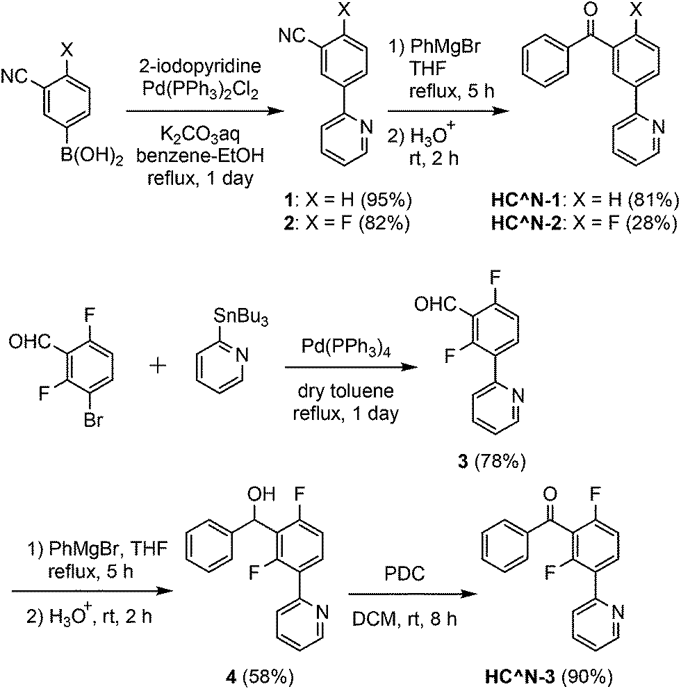
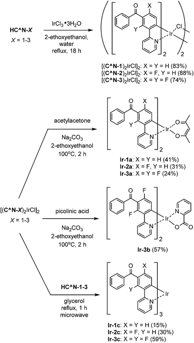
The 3′-benzoylated 2-phenylpyridine derivatives, HC^N-2 and HC^N-3, were newly prepared as the C^N ligands in accordance with Scheme 1; 2-fluoro-5-(pyridin-2-yl)benzonitrile (2) was obtained by the Suzuki–Miyaura cross-coupling reaction of (3-cyano-4-fluorophenyl)boronic acid with 2-iodopyridine in 82% yield, and was subjected to the addition of phenylmagnesium bromide, followed by hydrolysis, to yield HC^N-2 in 28% yield. On the other hand, HC^N-3 was obtained in three steps from 3-bromo-2,6-difluorobenzaldehyde. First, the starting material was subjected to the Stille coupling reaction with 2-(tributylstannyl)pyridine to obtain the phenylpyridine derivative 3 in 78% yield, which was reacted with phenylmagnesium bromide to yield the alcohol 4 in 58% yield. Finally, oxidation of 4 with pyridinium dichromate (PDC) in dichloromethane afforded HC^N-3 in 90% yield. To obtain the referential complexes, HC^N-1 was prepared in a similar way to the preparation of HC^N-2, although it was previously reported to be obtained by the Stille-type coupling reaction of (3-bromophenyl)phenylmethanone with 2-(tributylstannyl)pyridine.23
 |
| | Scheme 1 Syntheses of HC^N-1–3. | |
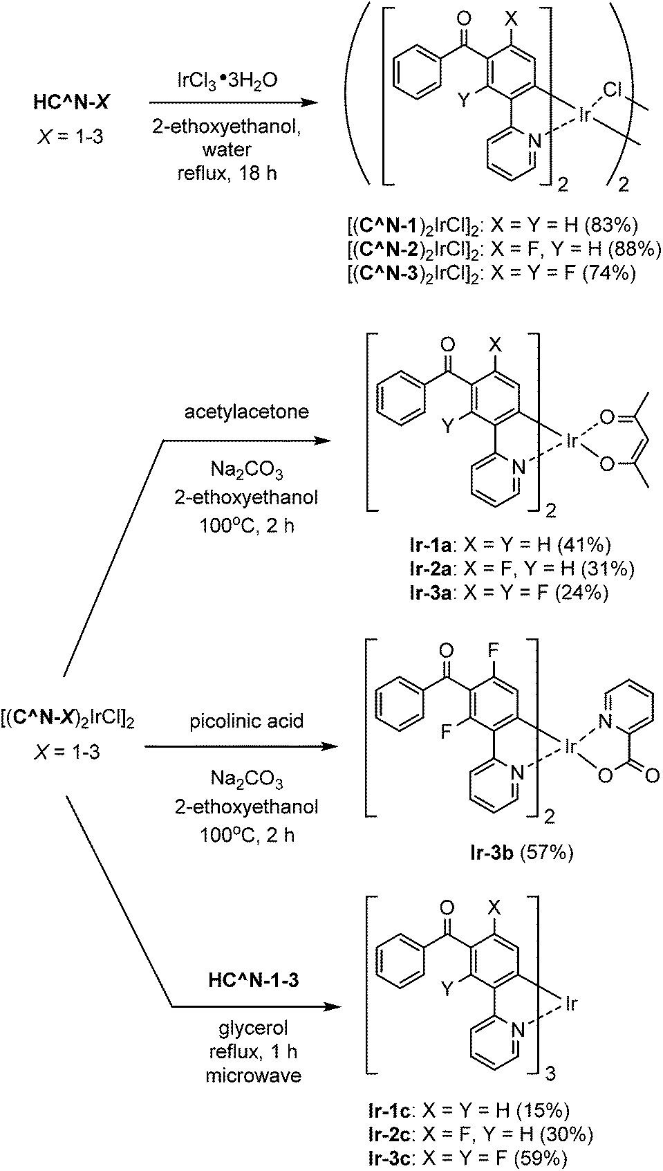
The syntheses of the 5′-benzoyl-substituted bis- and tris-cyclometalated iridium(III) complexes are shown in Scheme 2. The prepared benzoylated 2-phenylpyridines were reacted with hydrated IrCl3 to obtain μ-chloro-bridged iridium(III) dimers [(C^N-X)2IrCl]2 (X = 1–3) as precursors. These dinuclear complexes were reacted with acetylacetone in the presence of Na2CO3 to afford the corresponding bis-cyclometalated complexes, Ir-1a (the referential complex, reported in ref. 23), Ir-2a, and Ir-3a. The reaction of [(C^N-3)2IrCl]2 with picolinic acid was also carried out under the same conditions to obtain the picolinate analogue, Ir-3b. The tris-cyclometalated complexes, Ir-1c, Ir-2c, and Ir-3c, were also prepared by the microwave-assisted reaction of the corresponding [(C^N-X)2IrCl]2 with HC^N-X in 15–59% yields. The prepared complexes were characterized by 1H NMR, ESI-TOF mass spectrometry, and IR spectroscopy, as well as elemental analyses; 13C NMR spectra were also taken, except for the fluorinated compounds.
 |
| | Scheme 2 Syntheses of iridium(III) complexes. | |
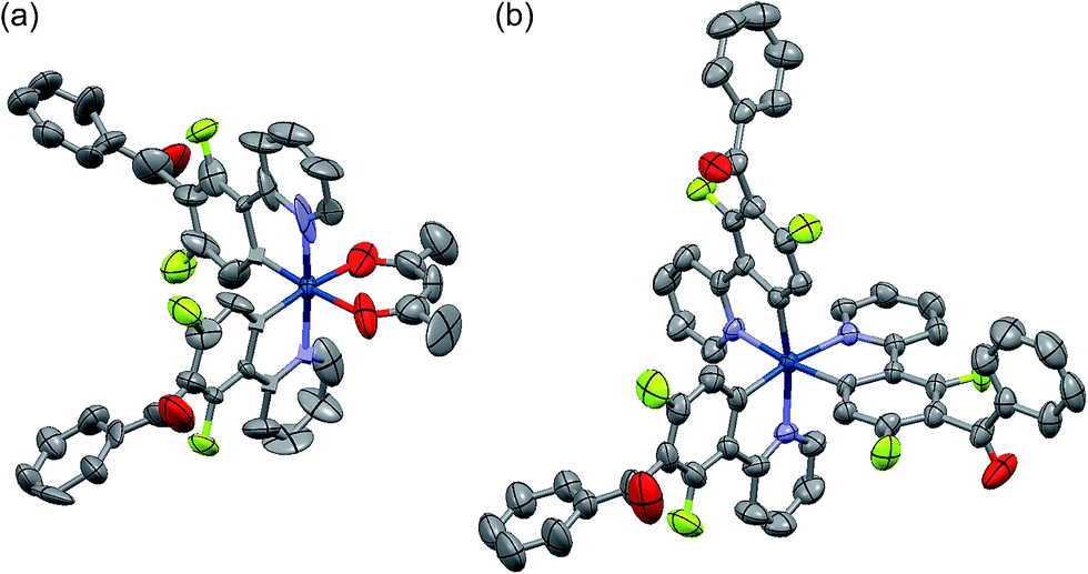
Among the developed cyclometalated iridium(III) complexes, the structures of Ir-3a and Ir-3c were characterized by X-ray crystallographic analysis, where suitable single crystals were obtained by slow diffusion of dichloromethane solutions of the complexes to hexane. Fig. 1 shows ORTEP drawings of Ir-3a and Ir-3c, and the crystal data are summarized in Table S1 (ESI†). The selected bond lengths and angles around the iridium center are also summarized in Tables S2 and S3 (ESI†). In the structure of Ir-3a, the ligands are arranged in a pseudo-octahedral geometry with a cis-C,C and trans-N,N configuration, as is observed for the typical bis-cyclometalated iridium(III) complexes so far reported.6,8,25 The bond lengths are also similar to the typical heteroleptic complexes: the lengths of the Ir–N, Ir–C, and Ir–O bonds are 2.04, 1.99–2.00, and 2.13 Å, respectively. Likewise, Ir-3c adopts a pseudo-octahedral geometry with a facial configuration, similar to typical phosphorescent homoleptic complexes,5,26 where the lengths of Ir–N and Ir–C bonds are 2.12–2.13 and 2.02–2.03 Å, respectively. It has been reported that the thermodynamically favored facial isomer is more emissive than the kinetically favored meridional one, and thus Ir-3c is expected to afford highly efficient phosphorescence.5 For Ir-3a and Ir-3c, the carbonyl moiety in each benzoyl group is distorted at 76.0–77.6° and 60.2–87.6°, respectively, with respect to the mean plane of the neighbouring phenyl ring of the C^N ligand. In addition, the phenyl and carbonyl moieties in the benzoyl group are twisted at 1.7–3.3° (Ir-3a) and at 2.9–25.4° (Ir-3c) to each other. The effect of the benzoyl group on the electronic structures is discussed below.
 |
| | Fig. 1 ORTEP drawings of (a) Ir-3a and (b) Ir-3c·2H2O with ellipsoids at the 50% probability level. The hydrogen atoms are omitted for clarity. | |
2.2. Light absorption and photoluminescent properties
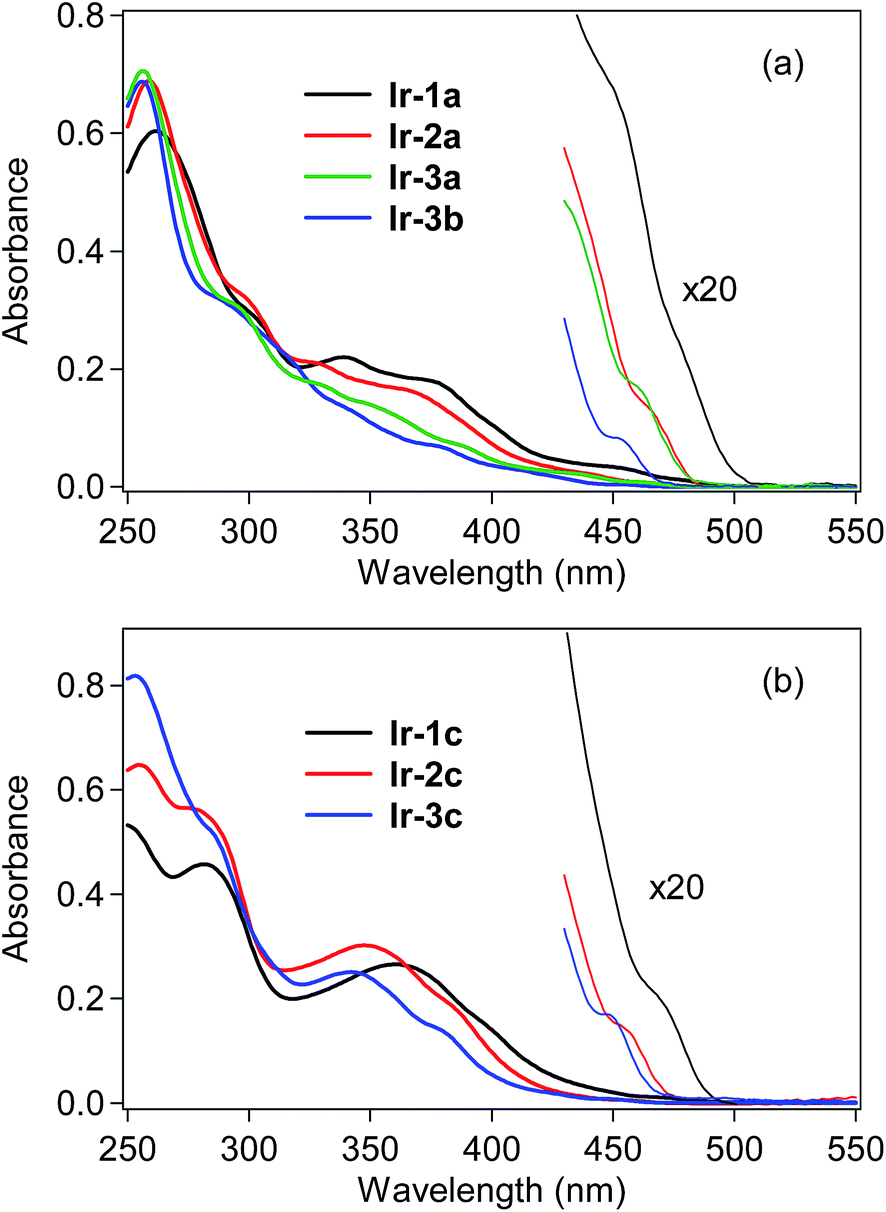
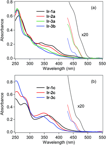
UV-vis absorption spectra of the bis- and tris-cyclometalated iridium(III) complexes were obtained in dichloromethane at rt, as shown in Fig. 2, and the spectral data are also summarized in Table 1. The absorption spectra of Ir-1a–3a and Ir-3b are shown in Fig. 2a. In the case of Ir-1a, intense absorption bands are observed from 250–320 nm, which are assigned to the spin-allowed ligand-center (1LC, 1π–π*) transitions at the C^N ligand, and the next bands at 330–420 nm are assigned to spin-allowed metal-to-ligand charge transfer (1MLCT, 1d–π*) transitions from the iridium core to the C^N ligand. As seen in the magnified spectrum, the weak shoulder-like absorption band around 475 nm with a lower molecular absorptivity is assigned to the spin-forbidden 3MLCT transition.6 Similar spectral features to Ir-1a are observed for the other bis-cyclometalated complexes, where the 3MLCT transition bands are blue-shifted to 465, 460 and 450 nm for Ir-2a, Ir-3a and Ir-3b, respectively, and the absorption onsets are also blue-shifted. This clearly indicates that the lowest triplet (T1) energy increases with an increase in the number of fluorine substituents, as well as after the replacement of the acac ancillary ligand with picolinate. In the case of the tris-cyclometalated complexes, the absorption spectral profiles are almost similar to those of the bis-cyclometalated complexes bearing the corresponding C^N ligands: the 1LC (250–300 nm), 1MLCT (300–410 nm), and 3MLCT (>440 nm) transitions are observed from the near-ultraviolet to the neighboring visible region (Fig. 2b). As observed for the bis-cyclometalated complexes, the 3MLCT transition band as well as the spectral onset is blue-shifted with an increase in the number of fluorine substituents.
 |
| | Fig. 2 UV-vis absorption spectra of (a) bis-cyclometalated and (b) tris-cyclometalated complexes in dichloromethane at rt. | |
Table 1 UV-vis absorption and photoluminescence data
| Comp'd |
λ
abs
a (nm) [log![[thin space (1/6-em)]](https://www.rsc.org/images/entities/char_2009.gif) εabs] εabs] |
λ
PL (nm)b |
E
T
e (eV) |
Φ
PL
|
τ
PL
b
,
f (μs) [χ2] |
| 298c K |
77d K |
|
The symbol “sh” indicates a peak observed as a shoulder.
Excited at 390 nm.
Obtained in deaerated dichloromethane.
Obtained in glassy 2Me-THF.
Determined from λPL at 77 K.
Monitored at shortest λPL of each complex.
|
|
Ir-1a
|
262 [4.78], 339 [4.34], 375 sh [4.26], 475 sh [3.12] |
502 |
488, 519 |
2.54 |
0.81 |
1.37 [1.0] |
|
Ir-2a
|
259 [4.81], 327 [4.31], 365 sh [4.21], 465 sh [2.82] |
483 |
470, 498 |
2.64 |
0.71 |
1.19 [1.0] |
|
Ir-3a
|
256 [4.85], 325 sh [4.25], 350 sh [4.15], 460 sh [2.93] |
479 |
464, 504 |
2.67 |
0.80 |
1.01 [1.1] |
|
Ir-3b
|
256 [4.84], 335 sh [4.16], 375 sh [3.85], 450 sh [2.62] |
464, 492 |
455, 487 |
2.73 |
0.82 |
1.97 [1.1] |
|
Ir-1c
|
282 [4.66], 360 [4.42], 395 sh [4.20], 470 sh [2.94] |
487 |
471, 509 |
2.63 |
0.82 |
1.16 [1.07] |
|
Ir-2c
|
255 [4.81], 274 sh [4.75], 347 [4.48], 380 sh [4.30], 455 sh [2.58] |
469, 497 |
459, 490 |
2.70 |
0.85 |
1.57 [1.07] |
|
Ir-3c
|
253 [4.91], 285 sh [4.71], 342 [4.40], 380 sh [4.13], 445 sh [2.88] |
463, 489 |
451, 483 |
2.75 |
0.90 |
1.54 [1.11] |
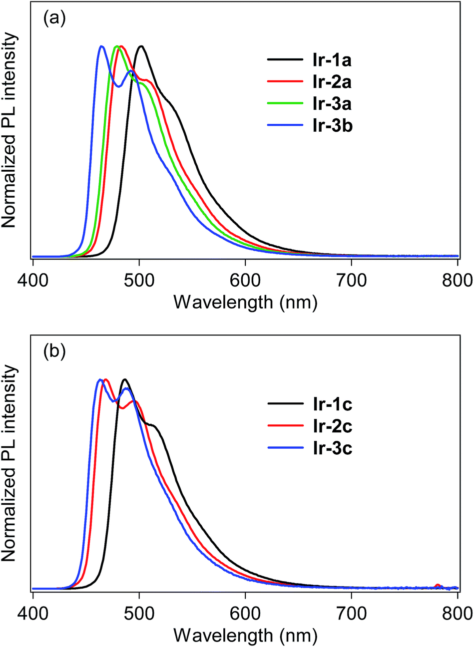
The photoluminescence (PL) spectra of bis- and tris-cyclometalated iridium(III) complexes in dichloromethane at rt are shown in Fig. 3. The spectral data are summarized in Table 1, along with PL quantum yields (ΦPL) and PL lifetimes (τPL). All the data were obtained for deaerated samples, which were kept away from luminescence quenching by oxygen. In the spectra of the bis-cyclometalated complexes (Fig. 3a), the λPL of Ir-1a was observed at 502 nm (green), and the emission band was blue-shifted with an increase in the number of fluorine substituents: Ir-2a and Ir-3a show their λPLs at 483 (bluish green) and 479 nm (bluish green), respectively. For the C^N-3-derived complexes, replacement of the acac ancillary ligand with picolinate gives rise to a further blue shift of 15 nm (λPL of Ir-3b; 464 nm), yielding sky-blue emission. Such a blue shift induced by picolinate is usually observed in typical bis-cyclometalated complexes.8,27 The blue shifts caused by the fluorine substituents as well as the ancillary ligand replacement are comparable to the blue-shifted spectral behaviour of the 3MLCT absorption (vide supra). The ΦPL values of Ir-1a, Ir-2a, Ir-3a and Ir-3b were determined as 0.81, 0.71, 0.80 and 0.82, respectively. Also, the τPLs of these complexes ranged from 1.01 to 1.97 μs, each of which was well fitted to a single-exponential decay. Fernández-Sánchez and coworkers reported (MeOCOdfppy)2Ir(pic) (MeOCOdfppy, 2-(4,6-difluoro-5-methoxycarbonylphenyl)pyridinate; pic, picolinate) and (CF3COdfppy)2Ir(pic) (CF3COdfppy; 2-(4,6-difluoro-5-(trifluoroacetyl)phenyl)pyridinate), which have a methoxycarbonyl and a trifluoroacetyl group, respectively, instead of the benzoyl group of Ir-3b. The complexes exhibited blue and deep blue PL at 463 and 459 nm, where the ΦPLs are 0.44 and 0.08 in acetonitrile, respectively.24 The λPL of Ir-3b is comparable to that of (MeOCOdfppy)2Ir(pic) and is red-shifted by 5 nm in comparison with that of (CF3COdfppy)2Ir(pic). One can see that this is because the electron-withdrawing ability of a benzoyl group is comparable to that of a methoxycarbonyl group and lower than that of a trifluoroacetyl group: the Hammet substituent constants (σp) of benzoyl, methoxycarbonyl and trifluoroacetyl groups are 0.43, 0.45 and 0.80, respectively.28 On the other hand, the ΦPL of Ir-3b is 0.94 in acetonitrile, which is much higher than that of (MeOCOdfppy)2Ir(pic) and (CF3COdfppy)2Ir(pic). As seen in Fig. 3b, the λPLs of Ir-1c, Ir-2c and Ir-3c were observed at 487 (bluish green), 470 (bluish green) and 463 nm (sky blue), respectively, blue-shifted by 14–17 nm in comparison with those of the corresponding acac-based bis-cyclometalated complexes. These blue shifts are caused by the relatively high ligand field strength of the C^N ligands in comparison with the acetylacetonate and picolinate anions.29,30 Thompson and coworkers reported that fac-(dfppy)3Ir (dfppy; 2-(4,6-difluorophenyl)pyridinate) exhibits blue PL at 468 nm in dichloromethane at rt.5 In the present case, the λPL of Ir-3c is 5 nm shorter than that of fac-(dfppy)3Ir. This blue-shift is obviously brought about by the introduction of a benzoyl group to the C^N ligand. The ΦPLs of Ir-1c, Ir-2c and Ir-3c were determined as 0.82, 0.85 and 0.90, respectively. Their τPLs were determined as 1.16–1.57 μs, similar to those of the corresponding bis-cyclometalated complexes. It is worthy to note that Ir-3c is more emissive than the representative blue phosphorescent organoiridium complexes, such as fac-(dfppy)3Ir (ΦPL; 0.43)5 and bis[(4,6-difluorophenyl)pyridinato-N,C2′]iridium(III) (picolinate-N,O), FIrpic (ΦPL; 0.87).31
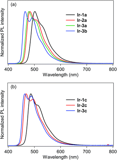 |
| | Fig. 3 Photoluminescence spectra of (a) bis- and (b) tris-cyclometalated complexes in dichloromethane at rt. | |
To determine the T1 energy values (ET), the phosphorescence spectra were measured in deaerated 2-MeTHF glassy matrices at 77 K (Fig. S2, ESI†), and the spectral data are also summarized in Table 1. All of the complexes are also intensely phosphorescent in the glass solutions at 77 K, showing more structured spectral shapes. The λPLs are blue-shifted by 9–16 nm in comparison with those obtained in dichloromethane at 298 K. The ETs obtained from the phosphorescence spectra at 77 K are almost comparable to the spectral onsets of the absorption spectra.
2.3. Electrochemical properties
As the energy levels of frontier orbitals are important in optimizing the device efficiency of OLEDs, the oxidation potentials of the present organoiridium(III) complexes (Eox1/2) vs. the ferrocenium/ferrocene (Fc+/Fc) redox couple were determined by cyclic voltammetry (CV) in anhydrous acetonitrile to estimate the effect of the substituents on the HOMO energy level (EHOMO). The EHOMOs derived from Eox1/2 are listed in Table 2. All the complexes exhibited pseudo-reversible oxidation cycles with Eox1/2 in the region of 0.655–1.03 V, although they showed irreversible reduction potentials, which prevented us from determining the LUMO energy levels. For Ir-1a, Ir-2a and Ir-3a, the EHOMO values were determined as −5.46, −5.55 and −5.67 eV, respectively, indicating that the HOMO is stabilized by an increase in the number of fluorine substituents. In addition, a benzoyl group also stabilizes the HOMO: the EHOMO of (ppy)2Ir(acac) is reported as −5.2 eV.27 For Ir-3b, EHOMO was determined as −5.81 eV, larger in a negative direction than that of Ir-3a (−5.67 eV). This indicates that the replacement of the ancillary ligand by picolinate also gives rise to stabilization of the HOMO level. In the case of the tris-cyclometalated complexes, the EHOMO values were determined as −5.57, −5.73 and −5.83 eV for Ir-1c, Ir-2c and Ir-3c, respectively. As is seen in the bis-cyclometalated complexes, the HOMO level of the tris-cyclometalated complex is stabilized by an increase in the number of fluorine substituents. Also, it is more stabilized in comparison with those of the corresponding bis-cyclometalated complexes (i.e., Ir-1a–3a).
Table 2 The calculated HOMO energy levels (EHOMO) corresponding to the potentials of oxidative cyclic voltammograms
| Comp'd |
E
ox1/2 (V) |
E
HOMO
a (eV) |
|
Calculated using the equation, −Eox1/2 – 4.80 eV.
|
|
Ir-1a
|
0.655 |
−5.46 |
|
Ir-2a
|
0.755 |
−5.55 |
|
Ir-3a
|
0.865 |
−5.67 |
|
Ir-3b
|
1.01 |
−5.81 |
|
Ir-1c
|
0.765 |
−5.57 |
|
Ir-2c
|
0.925 |
−5.73 |
|
Ir-3c
|
1.03 |
−5.83 |
2.4. DFT calculations
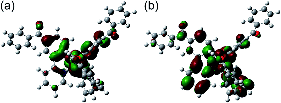
In order to discuss the effect of benzoyl and fluorine substituents on the EHOMOs, density functional theory (DFT) calculations were performed for the tris-cyclometalated complexes, using the Gaussian 09 program package.32 The structures of Ir-1c, Ir-2c and Ir-3c were optimized using the B3LYP functional,33 where the crystal structure of Ir-3c was used as an initial structure. LanL2DZ and 6-31G+(d) basis sets were employed for iridium and the other atoms, respectively, where LanL2DZ is one of the relativistic effective core potential (RECP) basis sets and consists of relativistic effective potentials and their associated basis sets.34 The optimized structure and the spatial distributions of the HOMO and LUMO of Ir-1c are shown in Fig. 4. Those of Ir-2c and Ir-3c are similar to Ir-1c (Fig. S4, ESI†). The calculated energy levels of the HOMO and LUMO (EHOMO,calcd and ELUMO,calcd, respectively) of these complexes are summarized in Table 3, together with the HOMO–LUMO energy gaps (Eg,calcd). The spatial distributions of the HOMOs and LUMOs of these complexes are almost the same as those of typical (ppy)3Ir-type complexes,19,27 and the carbonyl group shows an electronic contribution to both the HOMO and LUMO, in spite of disrupted π-conjugation due to deviation from the phenylpyridine plane. The EHOMO,calcd value of each complex is comparable to the EHOMO determined by CV, and an increase in the number of fluorine substituents leads to stabilization of the HOMO. Although the ELUMO,calcd is also decreased by an increase in the fluorine substituents, the EHOMO,calcd is decreased more drastically than ELUMO,calcd. This indicates that the high-lying triplet state is brought about by stabilization of the HOMO.
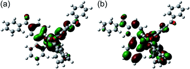 |
| | Fig. 4 Optimized geometry structure and electron configurations of (a) HOMO and (b) LUMO for Ir-1c. | |
Table 3 Calculated energy levels of the HOMO (EHOMO,calcd), LUMO (ELUMO,calcd) and energy gap (Eg,calcd)
| Comp'd |
E
HOMO,calcd (eV) |
E
LUMO,calcd (eV) |
E
g,calcd
a (eV) |
|
E
g,calcd = ELUMO,calcd − EHOMO,calcd.
|
|
Ir-1c
|
−5.40 |
−1.71 |
3.69 |
|
Ir-2c
|
−5.66 |
−1.87 |
3.79 |
|
Ir-3c
|
−5.87 |
−2.00 |
3.87 |
2.5. Fabrication of phosphorescent OLEDs
Using the developed bis- and tris-cyclometalated iridium(III) complexes as a phosphorescent dopant, we fabricated OLEDs consisting of a poly(9-vinylcarbazole) (PVCz) emitting layer (EML), device-1. The device structure is as follows; ITO (transparent anode, 150 nm, 10 Ω per square)/poly(3,4-ethylenedioxythiophene):poly(styrene-sulfonate) (PEDOT:PSS, 40 nm)/EML (100 nm)/CsF (1.0 nm)/Al (cathode, 250 nm). The EML consists of PVCz (hole-transporting host material), 1,3-bis(5-(4-(tert-butyl)phenyl)-1,3,4-oxadiazol-2-yl)benzene (OXD-7, electron-transporting material), and the phosphorescent dopant in a ratio of 10:3.0:0.40 (wt/wt/wt). The electroluminescence (EL) spectra of the fabricated devices are shown in Fig. 5, and the device properties are also summarized in Table 4. In the case of the bis-cyclometalated complexes, the devices exhibited EL spectra almost identical to the PL spectra of the constituent emitting dopants; the EL wavelengths (λEL) of the Ir-1a-, Ir-2a-, and Ir-3a-doped devices were 507, 485, and 481 nm, respectively. As for the Commission Internationale de L'éclairage (CIE) chromaticity coordinates (CIE (x, y)), the Ir-3a-doped device afforded a value of (0.19, 0.42). The ancillary ligand replacement in Ir-3a from acac to picolinate allowed us to fabricate an OLED emitting further blue-shifted EL: the device doped with Ir-3b exhibited sky-blue EL with a λEL of 469 nm and afforded a CIE (x, y) of (0.18, 0.34), where the value of the y-axis was improved in comparison with the Ir-3a-doped device. In terms of the device efficiency, the maximum external quantum efficiency (ηext) decreased slightly with an increase in the fluorine substituents; 2.44 (@10.0 V), 2.13 (@10.0 V), and 1.90% (@9.5 V) for the Ir-1a-, Ir-2a-, and Ir-3a-doped devices, respectively. In addition, the ancillary ligand replacement from acac to picolinate gave rise to deterioration of ηext down to 1.72% (@10.5 V, the Ir-3b-doped device). One can see that an increase in the ET is likely to bring about a back energy transfer to OXD-7 (ET = 2.7 eV).3
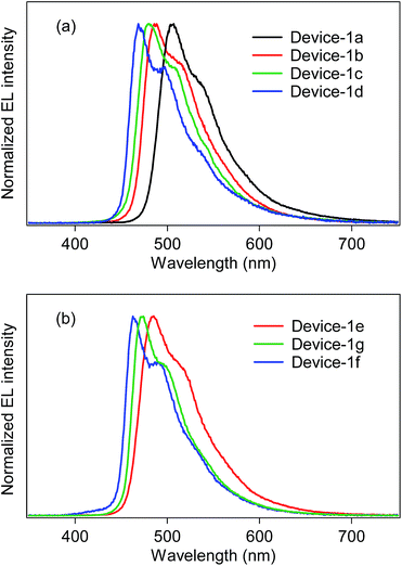 |
| | Fig. 5 EL spectra of device-1 employing (a) bis-cyclometalated and (b) tris-cyclometalated complexes. | |
Table 4 OLED performance of device-1
| Device |
Dopant |
V
turn-on
a (V) |
L
max
b (cd m−2) [@V] |
η
ext
b (%) [@V] |
η
j
b (cd A−1) [@V] |
η
p
b (lm W−1) [@V] |
CIE (x, y)b,c |
λ
EL
b
,
c (nm) |
|
The voltage where a luminance of more than 1 cd m−2 is observed.
The maximum values of luminance (Lmax), external efficiency (ηext), current efficiency (ηj), and power efficiency (ηp). The values in parentheses are the voltages at which they were obtained.
CIE chromaticity coordinates (CIE (x, y)) and EL wavelengths (λEL) were obtained at the voltages where the maximum luminance was observed.
|
| 1a |
Ir-1a
|
4.0 |
8210 [14.5] |
2.44 [10.0] |
7.67 [10.0] |
2.81 [7.5] |
(0.27, 0.60) |
507 |
| 1b |
Ir-2a
|
4.5 |
6090 [14.5] |
2.13 [10.0] |
5.70 [10.0] |
2.07 [8.0] |
(0.21, 0.50) |
485 |
| 1c |
Ir-3a
|
5.0 |
6660 [14.0] |
1.90 [9.5] |
4.46 [9.5] |
1.57 [8.0] |
(0.19, 0.42) |
481 |
| 1d |
Ir-3b
|
6.5 |
1350 [15.5] |
1.72 [10.5] |
3.62 [10.5] |
1.09 [9.5] |
(0.18, 0.34) |
469 |
| 1e |
Ir-1c
|
5.0 |
7290 [15.0] |
2.31 [11.0] |
7.39 [10.0] |
2.48 [9.0] |
(0.22, 0.48) |
485 |
| 1f |
Ir-2c
|
5.5 |
3930 [16.5] |
2.10 [10.5] |
5.90 [10.0] |
2.21 [7.0] |
(0.18, 0.34) |
469 |
| 1g |
Ir-3c
|
4.5 |
1510 [13.0] |
1.81 [8.0] |
3.47 [8.0] |
1.36 [8.0] |
(0.16, 0.28) |
462 |
In the case of the tris-cyclometalated complexes, the Ir-3c-doped device exhibited the most blue-shifted EL (λEL; 462 nm) among the OLEDs fabricated in this study. As expected from the results described above, the Ir-1c-doped device showed a better performance (ηext; 2.31% @ 11.0 V) than the Ir-2c- (ηext; 2.10% @ 10.5 V) and Ir-3c-doped devices (ηext; 1.81% @ 8.0 V): the increase in the number of fluorine substituents afforded a comparable or higher ET to facilitate the back energy transfer to OXD-7. In the Ir-3c-doped device, however, both the x- and y-axis values of the CIE chromaticity coordinate were improved in comparison with the Ir-3b-doped device, yielding a CIE (x, y) of (0.16, 0.28). This value is better than that of FIrpic (CIE (x, y) of (0.17, 0.34)), which is frequently used as a blue phosphorescent material.22
In order to improve the device efficiency of blue OLEDs, solution-processed multilayer OLEDs employing Ir-3 were fabricated (device-2), which have a so-called double-emitting layer (D-EML) structure.35 The device structure is as follows; ITO (transparent anode, 150 nm)/PEDOT:PSS (40 nm)/EML-1 (40 nm)/EML-2 (40 nm)/CsF (1.0 nm)/Al (cathode, 250 nm), where EML-1 is Ir-3-doped PVCz film (PVCz:Ir-3 = 1:0.1, wt/wt) and EML-2 is Ir-3-doped [1,1′:3′,1′′-terphenyl]-4,4′′-diylbis(diphenylphosphine oxide) (BPOPB)36 film (BPOPB:Ir-3 = 1:0.1, wt/wt). BPOPB is an electron-transporting material bearing a sufficiently high ET of 2.79 eV.36 The EML-2 was fabricated by spin-coating of a 2-propanol solution of Ir-3 and BPOPB onto the EML-1, utilizing the quite moderate solubility of Ir-3 in 2-propanol. The device performance and EL spectra of device-2 are shown in Table 5 and Fig. S7 (ESI†), respectively. The Ir-3a-doped D-EML OLED (device-2a) showed a better performance (ηext; 6.68% @ 11.0 V) than device-1c discussed above. The Ir-3b- and Ir-3c-doped devices (device-2b and device-2c, respectively) also exhibited improved ηexts of 8.55% (@9.0 V) and 7.46% (@10.0 V), respectively. Device-2b and device-2c exhibited sky-blue EL with almost identical CIE coordinates of (0.17, 0.33) and (0.17, 0.29) to the corresponding device-1, respectively.
Table 5 OLED performance of device-2
| Device |
Dopant |
V
turn-on
a (V) |
L
max
b (cd m−2) [@V] |
η
ext
b (%) [@V] |
η
j
b (cd A−1) [@V] |
η
p
b (lm W−1) [@V] |
CIE (x, y)bc |
λ
EL
b
c (nm) |
|
The voltage where a luminance of more than 1 cd m−2 is observed.
The maximum values of luminance (Lmax), external efficiency (ηext), current efficiency (ηj), power efficiency (ηp), CIE chromaticity coordinate (CIE (x, y)) and EL wavelength (λEL) for the devices. The values in parentheses are the voltages at which they were obtained.
Obtained at the voltage where the maximum luminance was observed.
|
| 2a |
Ir-3a
|
5.5 |
7560 [12.0] |
6.68 [9.0] |
15.0 [9.0] |
5.23 [9.0] |
(0.17, 0.40) |
480 |
| 2b |
Ir-3b
|
5.0 |
6220 [11.5] |
8.55 [9.0] |
17.6 [9.0] |
6.15 [9.0] |
(0.17, 0.33) |
469 |
| 2c |
Ir-3c
|
5.0 |
4760 [13.5] |
7.46 [10.0] |
13.9 [10.0] |
4.36 [10.0] |
(0.17, 0.29) |
466 |
3. Conclusions
In summary, novel blue phosphorescent bis- and tris-cyclometalated iridium(III) complexes with excellent PL quantum yields were successfully developed. In a series of bis-cyclometalated complexes, the 2-(4,6-difluoro-5-benzoylphenyl)pyridinate-based complex (Ir-3b) exhibited the most blue-shifted PL in combination with a picolinate ancillary ligand. A PVCz-based OLED, using Ir-3b as an emitting dopant, exhibited sky-blue EL along with a CIE (x, y) of (0.18, 0.34). Further ligand replacement with the identical C^N ligand afforded a facial isomer of the homoleptic tris-cyclometalated complex (Ir-3c), which also exhibited sky-blue PL. This tris-cyclometalated complex was an excellent blue phosphorescent dopant for OLED application with respect to the chromaticity coordinates, where the Ir-3b-based device afforded a CIE (x, y) of (0.16, 0.28). Although the PVCz-based OLEDs employing OXD-7 as an electron-transporting material showed low ηext (∼2%), D-EML OLEDs doped with Ir-3 showed an improved ηext of 6.68–8.55% without any considerable changes in the CIE coordinates. From the results of electrochemical and DFT studies, it was revealed that the blue-shifted PL and EL are mainly brought about by stabilization of the HOMO. Therefore, this work clearly demonstrates that the introduction of a benzoyl substituent into a fluorinated 2-phenylpyridinate cyclometalated ligand provides an opportunity to develop blue phosphorescent organoiridium(III) complexes with improved CIE chromaticity coordinates.
4. Experimental
4.1. Synthesis
All chemicals used for synthesis were purchased from Sigma-Aldrich Co., Tokyo Chemical Industry Co., Ltd, and Wako Pure Chemical Industries, Ltd and used without further purification. NMR spectra (1H and 13C) were obtained on a Jeol JNM-ECX400 (400 MHz for 1H and 100 MHz for 13C) spectrometer, using TMS as an internal standard (0.00 ppm). Electrospray ionization (ESI) mass spectra were measured on a Jeol JMS-T100LP. Elemental analyses were carried out on a J-Science Lab MICRO CORDER JM10 analyzer.
4.2. General procedure of synthesis of 1 and 2
To a mixture of 2-iodopyridine (0.25 g, 1.2 mmol), arylboronic acid (1.8 mmol), and PdCl2(PPh3)2 (0.069 g, 0.098 mmol) in a solvent mixture of benzene (5 mL) and ethanol (2 mL) was added Na2CO3aq (2 M, 5 mL). Then, the mixture was heated at 80 °C for 24 h under nitrogen. After cooling, the solvent was removed on a rotary evaporator. The residue was dissolved in dichloromethane, and the solution was washed with water (50 mL × 2) and sat. brine, and then dried over anhydrous MgSO4. The solvent was removed on a rotary evaporator, and the residue was purified by silica gel column chromatography using dichloromethane as eluent to obtain the target arylpyridine derivative.
3-(Pyridin-2-yl)benzonitrile (1).
95% yield. 1H NMR (400 MHz, CDCl3) δ 7.31 (ddd, J = 1.4, 4.8 and 7.4 Hz, 1H), 7.57 (t, J = 7.8 Hz, 1H), 7.68 (td, J = 1.4 and 7.8 Hz, 1H), 7.71–7.75 (m, 1H), 7.80 (dt, J = 1.8 and 7.8 Hz, 1H), 8.23 (td, J = 1.4 and 7.8 Hz, 1H), 8.31 (t, J = 1.4 Hz, 1H), 8.70–8.73 (m, 1H). This compound has been reported in ref. 37.
2-Fluoro-5-(pyridin-2-yl)benzonitrile (2).
82% yield. 1H NMR (400 MHz, CDCl3) δ 7.28–7.34 (m, 2H), 7.69 (d, J = 8.2 Hz, 1H), 7.80 (dt, J = 1.8 and 7.3 Hz, 1H), 8.22–8.27 (m, 1H), 8.30 (dd, J = 2.3 and 6.0 Hz, 1H), 8.70 (d, J = 5.0 Hz, 1H). IR (KBr, cm−1) 471, 735, 777, 843, 906, 1117, 1250, 1435, 1472, 1504, 2223. ESI-MS: m/z [M + H]+ calcd for C12H8FN2: 199.07; found: 199.07. Anal. calcd for C12H7FN2: C, 72.72; H, 3.56; N, 14.13. Found: C, 72.98; H, 3.65; N, 14.11.
4.3. Synthesis of 2,6-difluoro-3-(pyridin-2-yl)benzaldehyde (3)
A mixture of 3-bromo-2,6-difluorobenzaldehyde (0.442 g, 2.03 mmol) and Pd(PPh3)4 (0.121 g, 0.104 mmol) in dry toluene (10 mL) was heated up to 80 °C, then 2-(tributylstannyl)pyridine (0.884 g, 2.40 mmol) was added. The mixture was refluxed for 24 h. After the solution was cooled to rt, the reaction mixture was quenched with a saturated aqueous KF solution (10 mL). The solution was dissolved in dichloromethane (100 mL), washed with water (50 mL × 2) and sat. brine (100 mL), and then dried over anhydrous MgSO4. The solvent was removed on a rotary evaporator, and the residue was purified by silica gel column chromatography using ethyl acetate/hexane (2/3, v/v) as eluent to afford a white solid of 3 (0.346 g, 1.59 mmol, 78%). 1H NMR (400 MHz, CDCl3) δ 7.13 (dt, J = 1.4 and 9.2 Hz, 1H), 7.32 (q, J = 4.6 Hz, 1H), 7.78–7.81 (m, 2H), 8.29 (td, J = 6.4 and 8.7 Hz, 1H), 8.74 (td, J = 1.4 and 5.0 Hz, 1H), 10.44 (s, 1H). IR (KBr, cm−1) 501, 679, 756, 847, 1227, 1296, 1589, 1643. ESI-MS: m/z [M + H]+ calcd for C12H7F2NO: 220.06; found: 220.07. Anal. calcd for C12H7F2NO: C, 65.76; H, 3.22; N, 6.39. Found: C, 65.62; H, 3.50; N, 6.30.
4.4. General procedure of synthesis of HC^N-1, HC^N-2, and 4
A solution of phenylmagnesium bromide was prepared by dropwise addition of bromobenzene (1.57 g, 10 mmol) in 15 mL of dry THF via a dropping funnel to magnesium turnings (0.323 g, 13.3 mmol) suspended in dry THF (5 mL) under N2 at rt, where vigorous stirring was essential. The obtained solution of the Grignard reagent (12 mL) was added slowly to a solution of 1–3 (2 mmol) in dry THF (4 mL), and then the reaction mixture was heated at reflux for 5 h. After cooling, 1 M H2SO4 (10 mL) was added, and the obtained mixture was stirred at rt for 2 h, followed by neutralization using a saturated aqueous solution of NaHCO3. After the mixture was concentrated on a rotary evaporator, dichloromethane (50 mL) was added to the residual solution. This mixture was vigorously shaken in a separation funnel, and the organic layer was separated, washed with water (50 mL × 2) and sat. brine, and then dried over anhydrous MgSO4. The solvent was removed on a rotary evaporator, and the residue was purified by silica gel column chromatography using ethyl acetate/hexane (1/3, v/v) to obtain the product.
Phenyl(3-(pyridin-2-yl)phenyl)methanone (HC^N-1).
81% yield. 1H NMR (400 MHz, CDCl3) δ 7.22–7.29 (m, 1H), 7.49 (t, J = 7.6 Hz, 2H), 7.58–7.62 (m, 2H), 7.75–7.78 (m, 2H), 7.81–7.86 (m, 3H), 8.26 (td, J = 1.4 and 7.8 Hz, 1H), 8.39 (t, J = 1.8 Hz, 1H), 8.69 (d, J = 5.0, 1H). This compound has been reported in ref. 23.
(2-Fluoro-5-(pyridin-2-yl)phenyl)(phenyl)methanone (HC^N-2).
28% yield. 1H NMR (400 MHz, CDCl3) δ 7.22–7.29 (m, 2H, masked by CHCl3), 7.48 (t, J = 7.7 Hz, 2H), 7.60 (tt, J = 1.4 and 7.3 Hz, 1H), 7.69–7.79 (m, 2H), 7.87 (d, J = 8.2 Hz, 2H), 8.15 (dd, J = 2.5 and 6.6 Hz, 1H), 8.18–8.23 (m, 1H), 8.65–8.69 (m, 1H). IR (KBr, cm−1) 602, 756, 849, 1157, 1250, 1312, 1412, 1504, 1597, 1659. ESI-MS: m/z [M + Na]+ calcd for C18H12FNNaO: 300.08; found: 300.07. Anal. calcd for C18H12FNO: C, 77.97; H, 4.36; N, 5.05. Found: C, 77.79; H, 4.35; N, 5.06.
(2,6-Difluoro-3-(pyridin-2-yl)phenyl)(phenyl)methanol (4).
74% yield. 1H NMR (400 MHz, CDCl3) δ 2.91 (td, J = 2.3 and 9.2 Hz, 1H), 6.33 (d, J = 8.7 Hz, 1H), 7.03 (dt, J = 1.4 and 9.2 Hz, 1H), 7.23–7.30 (m, 2H, masked by CHCl3), 7.32–7.37 (m, 2H), 7.42 (d, J = 7.3 Hz, 2H), 7.67–7.76 (m, 2H), 7.92 (td, J = 6.4 and 8.7 Hz, 1H), 8.70 (td, J = 1.4 and 4.6 Hz, 1H). IR (KBr, cm−1) 1026, 1177, 1207, 1412, 1435, 1466, 1589, 3024, 3059, 3232. ESI-MS: m/z [M + H]+ calcd for C18H13F2NO: 298.10; found: 298.10. Anal. calcd for C18H13F2NO: C, 72.72; H, 4.41; N, 4.71. Found: C, 72.52; H, 4.54; N, 4.59.
4.5. Synthesis of (2,6-difluoro-3-(pyridin-2-yl)phenyl)(phenyl)-methanone (HC^N-3)
To a solution of 4 (0.243 g, 0.820 mmol) in dichloromethane (40 mL) was added a 4 Å molecular sieve (0.832 g) and pyridinium dichromate (0.539 g, 1.45 mmol) at rt. The reaction mixture was stirred at rt for 8 h, then the suspension was filtered over a Celite® pad, and the solution was evaporated to dryness. The residue was dissolved in dichloromethane (100 mL), and the solution was washed with water (50 mL × 2) and sat. brine (100 mL), and then dried over anhydrous MgSO4. The solvent was removed on a rotary evaporator, and the residue was purified by silica gel column chromatography using ethyl acetate/chloroform (1/10, v/v) as eluent to afford a pale yellow oil, HC^N-3 (0.217 g, 0.735 mmol, 90%). 1H NMR (400 MHz, CDCl3) δ 7.10–7.16 (m, 1H), 7.24–7.30 (m, 1H, masked by CHCl3), 7.49 (t, J = 7.7 Hz, 2H), 7.62 (t, J = 7.7 Hz, 1H), 7.72–7.75 (m, 2H), 7.90 (d, J = 7.7 Hz, 2H), 8.16 (td, J = 6.8 and 8.6 Hz, 1H), 8.72 (d, J = 4.5 Hz, 1H). IR (KBr, cm−1) 764, 1065, 1126, 1258, 1319, 1582, 1666, 3063. ESI-MS: m/z [M + Na]+ calcd for C18H11F2NNaO: 318.07; found: 318.07. Anal. calcd for C18H11F2N2O: C, 73.22; H, 3.75; N, 4.74. Found: C, 73.21; H, 3.94; N, 4.77.
4.6. General procedure of synthesis of μ-chloro-bridged iridium(III) dimers [(C^N-X)2IrCl]2
The μ-chloro-bridged iridium(III) dimers [(C^N-X)2IrCl]2 (X = 1–3) were prepared according to the conventional procedure.6 To a solution of the cyclometalated ligand (HC^N-X, 2.5 mmol) in 2-ethoxyethanol (50 mL) was added a solution of IrCl3·3H2O (1.2 mmol) in water (50 mL), and the mixture was heated at 100 °C in an oil bath for 18 h. After cooling, water (100 mL) was added, and the obtained precipitate was collected by filtration and washed with ethanol (20 mL) and hexane (20 mL) to afford [(C^N-X)2IrCl]2 in 83, 88 and 74% yields for X = 1, 2 and 3, respectively. The obtained materials were highly insoluble, and thus were used in the next reaction without further purification in accordance with conventional procedures.
4.7. General procedure of synthesis of bis-cyclometalated complexes
A mixture of [(C^N-X)2IrCl]2 (0.10 mmol), acetylacetone or picolinic acid (0.40 mmol), and Na2CO3 (0.18 g, 1.7 mmol) in 2-ethoxyethanol (30 mL) was heated at 100 °C under nitrogen for 2 h. After cooling, the solvent was removed on a rotary evaporator. The residue was dissolved in dichloromethane, and the solution was washed with water (20 mL × 2) and sat. brine, and dried over anhydrous Na2SO4. The solvent was removed on a rotary evaporator, and the residue was purified by alumina column chromatography using dichloromethane as eluent. Further purification was carried out by recrystallization from chloroform–hexane or dichloromethane–hexane.
Bis[2-(5-benzoylphenyl)pyridinato-N,C2′]iridium(III) (acetylacetonate-O,O) (Ir-1a).
41% yield. 1H NMR (400 MHz, CDCl3) δ 1.74 (s, 6H), 5.33 (s, 1H), 6.42 (d, J = 7.8 Hz, 2H), 7.06 (dd, J = 1.9 and 7.8 Hz, 2H), 7.43–7.49 (m, 6H), 7.57 (tt, J = 1.5 and 7.6 Hz, 2H), 7.67–7.70 (m, 4H), 8.01 (td, J = 1.5 and 7.8 Hz, 2H), 8.13 (d, J = 1.8 Hz, 2H), 8.20 (d, J = 8.2 Hz, 2H), 8.64 (d, J = 5.0 Hz, 2H). This compound has been reported in ref. 23.
Bis[2-(4-fluoro-5-benzoylphenyl)pyridinato-N,C2′]iridium(III) (acetylacetonate-O,O) (Ir-2a).
31% yield. 1H NMR (400 MHz, acetone-d6) δ 1.78 (s, 6H), 5.36 (s, 1H), 5.96 (d, J = 11.0 Hz, 2H), 7.45–7.50 (m, 6H), 7.59 (tt, J = 7.8 Hz, 2H), 7.71–7.76 (m, 4H), 7.99 (d, J = 7.3 Hz, 2H), 8.03 (dt, J = 1.4 and 7.8 Hz, 2H), 8.22 (d, J = 8.2 Hz, 2H), 8.46 (dd, J = 0.9 and 5.5 Hz, 2H). IR (KBr, cm−1) 611, 762, 851, 1032, 1155, 1225, 1259, 1396, 1518, 1597, 1647. ESI-MS: m/z [M + Na]+ calcd for C41H29F2IrN2NaO4: 867.16; found: 867.16. Anal. calcd for C41H29F2IrN2O4: C, 58.35; H, 3.46; N, 3.32. Found: C, 58.22; H, 3.62; N, 3.28.
Bis[2-(4,6-difluoro-5-benzoylphenyl)pyridinato-N,C2′]iridium(III) (acetylacetonate-O,O) (Ir-3a).
24% yield. 1H NMR (400 MHz, acetone-d6) δ 1.79 (s, 6H), 5.39 (s, 1H), 5.88 (d, J = 9.2 Hz, 2H), 7.49–7.56 (m, 6H), 7.66 (tt, J = 1.4 and 7.3 Hz, 2H), 7.84 (d, J = 7.3 Hz, 4H), 8.07 (dt, J = 1.4 and 7.9 Hz, 2H), 8.28 (d, J = 8.2 Hz, 2H), 8.63 (dd, J = 0.9 and 6.0 Hz, 2H). IR (KBr, cm−1) 673, 706, 733, 752, 773, 945, 1252, 1277, 1396, 1472, 1514, 1578, 1647. ESI-MS: m/z [M + Na]+ calcd for C41H27F4IrN2NaO4: 903.14; found: 903.10. Anal. calcd for C41H27F4IrN2O4: C, 55.97; H, 3.09; N, 3.18. Found: C, 55.84; H, 3.25; N, 3.29.
Bis[2-(4,6-difluoro-5-benzoylphenyl)pyridinato-N,C2′]iridium(III) (picolinate-N,O) (Ir-3b).
40% yield. 1H NMR (400 MHz, CD2Cl2) δ 5.80 (d, J = 9.2 Hz, 1H), 6.01 (d, J = 9.2 Hz, 1H), 7.07 (ddd, J = 1.4, 5.9 and 7.6 Hz, 1H), 7.26 (ddd, J = 1.4, 5.9 and 7.3 Hz, 1H), 7.43–7.53 (m, 6H), 7.57–7.64 (m, 2H), 7.77–7.89 (m, 7H), 7.99 (dt, J = 1.4 and 7.6 Hz, 1H), 8.22 (d, J = 8.2 Hz, 1H), 8.25–8.32 (m, 2H), 8.74 (dd, J = 0.9 and 6.0 Hz, 1H). IR (KBr, cm−1) 766, 1065, 1128, 1169, 1269, 1312, 1325, 1398, 1474, 1514, 1562, 1580, 1659. ESI-MS: m/z [M + Na]+ calcd for C42H24F4IrN3NaO4: 926.12; found: 926.10. Anal. calcd for C42H24F4IrN3O4: C, 55.87; H, 2.68; N, 4.65. Found: C, 55.49; H, 2.88; N, 4.53.
4.8. General procedure of synthesis of tris-cyclometalated complexes
In a 50 mL round-bottom flask, a mixture of [(C^N-X)2IrCl]2 (0.050 mmol) and HC^N-X (0.5 mmol) in glycerol (30 mL) was added. This flask was set up in a J-Science Lab GM·IC Microwave Applicator, and irradiated with microwaves (2450 MHz, 300 W), and the suspension was refluxed for 1 h. After cooling, the reaction mixture was added to 100 mL of 3% NaClaq. The resultant suspension was extracted with ethyl acetate/hexane (1/1, v/v), and dried over anhydrous Na2SO4. The solvent was removed on a rotary evaporator, and the residue was purified by silica gel column chromatography using ethyl acetate/hexane (2/1, v/v) as eluent. Further purification was carried out by recrystallization from chloroform–hexane or dichloromethane–hexane.
fac-Tris[2-(5-benzoylphenyl)pyridinato-N,C2′]iridium(III) (Ir-1c).
15% yield. 1H NMR (400 MHz, CDCl3) δ 6.95 (d, J = 8.2 Hz, 3H), 7.01 (ddd, J = 0.9, 5.7 and 7.0 Hz, 3H), 7.21 (dd, J = 1.8 and 7.7 Hz, 3H), 7.42 (t, J = 7.5 Hz, 6H), 7.48–7.57 (m, 6H), 7.69–7.78 (m, 9H), 8.05 (d, J = 8.2 Hz, 3H), 8.27 (d, J = 1.4 Hz, 3H). 13C NMR (100 MHz, CDCl3) δ 119.72, 122.96, 125.28, 128.03, 129.70, 130.21, 131.50, 132.32, 136.43, 137.07, 138.73, 144.55, 147.12, 165.31, 170.50, 196.89. IR (KBr, cm−1) 708, 752, 773, 945, 1254, 1275, 1396, 1471, 1516, 1578, 1647. ESI-MS: m/z [M + Na]+ calcd for C54H36IrN3NaO3; 990.23; found: 990.23. Anal. calcd for C54H36IrN3O3: C, 67.06; H, 3.75; N, 4.34. Found: C, 67.12; H, 3.45; N, 4.57.
fac-Tris[2-(5-benzoyl-4-fluorophenyl)pyridinato-N,C2′]iridium(III) (Ir-2c).
30% yield. 1H NMR (400 MHz, CDCl3) δ 6.62 (d, J = 11.5 Hz, 3H), 7.03 (t, J = 5.9 Hz, 3H), 7.43 (t, J = 7.8 Hz, 6H), 7.49–7.56 (m, 6H), 7.75 (t, J = 8.0 Hz, 3H), 7.82 (d, J = 7.8 Hz, 6H), 7.97 (d, J = 8.2 Hz, 3H), 8.02 (d, J = 6.9 Hz, 3H). IR (KBr, cm−1) 766, 1065, 1128, 1169, 1269, 1325, 1398, 1514, 1580, 1659. ESI-MS: m/z [M + Na]+ calcd for C54H33F3IrN3NaO3: 1044.20; found: 1044.21. Anal. calcd for C54H33F3IrN3O3: C, 68.52; H, 3.26; N, 4.12. Found: C, 68.50; H, 3.45; N, 3.89.
fac-Tris[2-(5-benzoyl-4,6-difluorophenyl)pyridinato-N,C2′]iridium(III) (Ir-3c).
59% yield. 1H NMR (400 MHz, CD2Cl2) δ 6.52 (d, J = 9.6 Hz, 3H), 7.07 (t, J = 6.6 Hz, 3H), 7.45 (t, J = 7.8 Hz, 6H), 7.53–7.61 (m, 6H), 7.79 (t, J = 7.8 Hz, 3H), 7.86 (d, J = 7.8 Hz, 6H), 8.32 (d, J = 9.2 Hz, 3H). IR (KBr, cm−1) 708, 754, 947, 1016, 1030, 1167, 1258, 1271, 1317, 1404, 1474, 1531, 1599, 1666, 3061. ESI-MS: m/z [M + Na]+ calcd for C54H30F6IrN3NaO3: 1098.17; found: 1098.18. Anal. calcd for C54H30F6IrN3O3: C, 60.33; H, 2.81; N, 3.91. Found: C, 60.63; H, 3.21; N, 4.01.
4.9. X-ray crystallography
Diffraction data for Ir-3a and Ir-3c were collected on a Rigaku AFC-7 Mercury CCD diffractometer, using graphite monochromated Mo-Kα radiation (λ = 0.71075 Å). The cell parameters were collected at a temperature of 20 ± 1 °C to maximum 2θ values of 61.1° and 61.6° for Ir-3a and Ir-3c, respectively. The structures were solved by direct methods using the SHELX97 (ref. 38) and the SIR92 (ref. 39) programs for Ir-3a and Ir-3c, respectively, and expanded using Fourier techniques on the DIRDIF99 (ref. 40) program. All calculations were performed using the Crystal Structure 4.0 (ref. 41) and Crystal Structure 3.8 (ref. 42) software packages for Ir-3a and Ir-3c, respectively. The crystal data and refinement details of the crystal structure determination are given in Table S1 (ESI†).
4.10. Spectroscopic measurements
UV-vis absorption spectra were measured on a Shimadzu UV-3600 spectrophotometer. PL spectra were measured on a Horiba Jobin Yvon Fluorolog-3 spectrophotometer. Phosphorescent spectra were measured for samples in a 2-methyltetrahydrofuran glass matrix at 77 K on a Jasco FP-6600 spectrometer equipped with a Jasco PMU-183 phosphorescence measurement base unit. τPLs were obtained on a Horiba Jobin Yvon FluoroCube spectroanalyzer using a 390 nm nanosecond-order LED light source. ΦPLs were obtained on a Hamamatsu Photonics C9920 PL quantum yield measurement system using an excitation wavelength of 390 nm. Except for UV-vis absorption spectroscopy, the sample solutions were deaerated by N2 bubbling, followed by complete sealing, and the analyses were carried out just after preparation of the samples. For the PL measurement, FIrpic, as a referential blue phosphorescent organoiridium(III) complex, was purchased from Luminescence Technology Corp. and used without further purification.
4.11. Electrochemical properties
Cyclic voltammograms of the organoiridium(III) complexes were recorded on a Hokuto Denko HZ-5000 electrochemical measurement system at a scanning rate of 100 mV s−1. The measurements were performed in deaerated acetonitrile, where 0.1 M tetrabutylammonium perchlorate was used as a supporting electrolyte at room temperature. The potentials were recorded relative to an Ag/AgNO3 (0.1 M) reference electrode with a Pt wire being used for both working and counter electrodes. An oxidation potential, Eox1/2, was determined using the Fc+/Fc redox couple as an external standard (0.000 V).
4.12. Fabrication of OLEDs
For fabrication of OLEDs, PVCz (Mw = 25000−50000) was purchased from Sigma-Aldrich Co., and used after purification by reprecipitation from THF to methanol. PEDOT:PSS (Clevios P CH 8000) and OXD-7 were purchased from Heraeus GmbH and Luminescence Technology Corp., respectively. BPOPB was prepared according to a literature report.36 Cesium fluoride and aluminium wires were purchased from Wako Pure Chemical Industries, Ltd. and the Nilaco Co., respectively.
Fabrication of device-1.
A pre-patterned ITO glass substrate as an anode was routinely cleaned by ultrasonic treatment in an aqueous detergent solution, distilled water, acetone, chloroform, hexane and 2-propanol. PEDOT:PSS (40 nm) was spin-coated onto an ITO layer pretreated with UV-O3 and then dried at 115 °C for 1 h. For fabrication of an EML, a mixture of PVCz, OXD-7, and an organoiridium(III) complex in dry toluene (PVCz; 10 mg/0.7 mL of toluene) was filtered through a 0.2 μm Millex-FG filter (Millipore). The obtained stock solution was then spin-coated onto the PEDOT:PSS layer under an argon atmosphere. Thereafter, cesium fluoride (1.0 nm) and aluminum (250 nm) layers were successively embedded on the EML by vacuum deposition with a base pressure of ca. 1 × 10⁻⁴ Pa. Finally, the device was covered with a glass cap and encapsulated with a UV-curing epoxy resin under a dry argon atmosphere to keep oxygen and moisture away from the device. The emitting area was 10 mm2 (2 mm × 5 mm). The device fabrication was carried out in a glovebox filled with dry argon, except for the preparation of the PEDOT:PSS layer.
Fabrication of device-2.
A PEDOT:PSS layer (40 nm) was fabricated on an ITO glass substrate using the same method as for device-1. For fabrication of an EML-1, a mixture of PVCz and an organoiridium(III) complex in dry toluene (PVCz; 6.4 mg/0.7 mL of toluene) was filtered through a 0.2 μm Millex-FG filter (Millipore). The obtained stock solution was then spin-coated onto the PEDOT:PSS layer under an argon atmosphere. Then, for fabrication of an EML-2, a mixture of BPOPB and an organoiridium(III) complex in dry 2-propanol (BPOPB; 4.1 mg/0.7 mL of 2-propanol) was filtered through a 0.2 μm Millex-FG filter (Millipore). The obtained stock solution was then spin-coated onto the EML-1 under an argon atmosphere. Thereafter, cesium fluoride (1.0 nm) and aluminum (250 nm) layers were embedded, and then the device was covered with a glass cap in the same way as device-1.
Acknowledgements
This work was partially supported by a Grant-in-Aid for Scientific Research on Innovative Areas “New Polymeric Materials Based on Element-Blocks (No. 2401)” (15H00759) of The Ministry of Education, Culture, Sports, Science, and Technology, Japan.
Notes and references
- H. Xu, R. Chen, Q. Sun, W. Lai, Q. Su, W. Huang and X. Liu, Chem. Soc. Rev., 2014, 43, 3259–3302 RSC.
- Y. Chi and P. T. Chou, Chem. Soc. Rev., 2010, 39, 638–655 RSC.
- Y. Tao, C. Yang and J. Qin, Chem. Soc. Rev., 2011, 40, 2943–2970 RSC.
- C. Adachi, M. A. Baldo, M. E. Thompson and S. R. Forrest, J. Appl. Phys., 2001, 90, 5048 CrossRef CAS.
- A. B. Tamayo, B. D. Alleyne, P. I. Djurovich, S. Lamansky, I. Tsyba, N. N. Ho, R. Bau and M. E. Thompson, J. Am. Chem. Soc., 2003, 125, 7377–7387 CrossRef CAS PubMed.
- S. Lamansky, P. Djurovich, D. Murphy, F. Abdel-Razzaq, H.-E. Lee, C. Adachi, P. E. Burrows, S. R. Forrest and M. E. Thompson, J. Am. Chem. Soc., 2001, 123, 4304–4312 CrossRef CAS PubMed.
- J. Brooks, Y. Babayan, S. Lamansky, P. I. Djurovich, I. Tsyba, R. Bau and M. E. Thompson, Inorg. Chem., 2002, 41, 3055–3066 CrossRef CAS PubMed.
- S. Lamansky, P. Djurovich, D. Murphy, F. Abdel-Razzaq, R. Kwong, I. Tsyba, M. Bortz, B. Mui, R. Bau and M. E. Thompson, Inorg. Chem., 2001, 40, 1704–1711 CrossRef CAS PubMed.
- X. Yang, G. Zhou and W.-Y. Wong, Chem. Soc. Rev., 2015, 44, 8484–8575 RSC.
- J. Zhao, Y. Yu, X. Yang, X. Yan, H. Zhang, X. Xu, G. Zhou, Z. Wu, Y. Ren and W.-Y. Wong, ACS Appl. Mater. Interfaces, 2015, 7, 24703–24714 CAS.
- S. Koseki, N.-o. Kamata, T. Asada, S. Yagi, H. Nakazumi and T. Matsushita, J. Phys. Chem. C, 2013, 117, 5314–5327 CAS.
- G. M. Farinola and R. Ragni, Chem. Soc. Rev., 2011, 40, 3467–3482 RSC.
- H. Tsujimoto, S. Yagi, S. Ikawa, H. Asuka, T. Maeda, H. Nakazumi and Y. Sakurai, J. Jpn. Soc. Colour Mater., 2010, 83, 207–214 CrossRef CAS.
- S. Ikawa, S. Yagi, T. Maeda, H. Nakazumi and Y. Sakurai, J. Lumin., 2014, 155, 368–373 CrossRef CAS.
- S. Lee, S. O. Kim, H. Shin, H. J. Yun, K. Yang, S. K. Kwon, J. J. Kim and Y. H. Kim, J. Am. Chem. Soc., 2013, 135, 14321–14328 CrossRef CAS PubMed.
- S. J. Lee, K. M. Park, K. Yang and Y. Kang, Inorg. Chem., 2009, 48, 1030–1037 CrossRef CAS PubMed.
- C.-H. Yang, S.-W. Li, Y. Chi, Y.-M. Cheng, Y.-S. Yeh, P.-T. Chou, G.-H. Lee, C.-H. Wang and C.-F. Shu, Inorg. Chem., 2005, 44, 7770–7780 CrossRef CAS PubMed.
- S.-J. Yeh, C.-T. Chen, Y.-H. Song, Y. Chi and M.-H. Ho, J. Soc. Inf. Disp., 2005, 13, 857–862 CrossRef CAS.
- N. G. Park, G. C. Choi, Y. H. Lee and Y. S. Kim, Curr. Appl. Phys., 2006, 6, 620–626 CrossRef.
- V. V. Grushin, N. Herron, D. D. LeCloux, W. J. Marshall, V. A. Petrov and Y. Wang, Chem. Commun., 2001, 1494–1495 RSC.
- H.-J. Seo, K.-M. Yoo, M. Song, J. S. Park, S.-H. Jin, Y. I. Kim and J.-J. Kim, Org. Electron., 2010, 11, 564–572 CrossRef CAS.
- S. Tokito, T. Iijima, Y. Suzuri, H. Kita, T. Tsuzuki and F. Sato, Appl. Phys. Lett., 2003, 83, 569 CrossRef CAS.
- K. H. Lee, J. S. Hwang, D. H. Chae, S. J. Lee, Y. K. Kim and S. S. Yoon, Mol. Cryst. Liq. Cryst., 2012, 563, 185–194 CrossRef CAS.
- M. Marín-Suárez, B. F. E. Curchod, I. Tavernelli, U. Rothlisberger, R. Scopelliti, I. Jung, D. D. Censo, M. Grätzel, J. F. Fernández-Sánchez, A. Fernández-Gutiérrez, M. K. Nazeeruddin and E. Baranoff, Chem. Mater., 2012, 24, 2330–2338 CrossRef.
- S. Ikawa, S. Yagi, T. Maeda, H. Nakazumi, H. Fujiwara and Y. Sakurai, Dyes Pigm., 2012, 95, 695–705 CrossRef CAS.
- S. Ikawa, S. Yagi, T. Maeda, H. Nakazumi, H. Fujiwara, S. Koseki and Y. Sakurai, Inorg. Chem. Commun., 2013, 38, 14–19 CrossRef CAS.
- J. Frey, B. F. Curchod, R. Scopelliti, I. Tavernelli, U. Rothlisberger, M. K. Nazeeruddin and E. Baranoff, Dalton Trans., 2014, 43, 5667–5679 RSC.
- C. Hansch, A. Leo and R. W. Taft, Chem. Rev., 1991, 91, 165–195 CrossRef CAS.
- R. Wang, D. Liu, R. Zhang, L. Deng and J. Li, J. Mater. Chem., 2012, 22, 1411–1417 RSC.
- G.-J. Zhou, W.-Y. Wong, B. Yao, Z. Xie and L. Wang, J. Mater. Chem., 2008, 18, 1799 RSC.
- Measured for a commercially available sample of FIrpic in deaerated dichloromethane.
-
M. J. Frisch, G. W. Trucks, H. B. Schlegel, G. E. Scuseria, M. A. Robb, J. R. Cheeseman, G. Scalmani, V. Barone, B. Mennucci, G. A. Petersson, H. Nakatsuji, M. Caricato, X. Li, H. P. Hratchian, A. F. Izmaylov, J. Bloino, G. Zheng, J. L. Sonnenberg, M. Hada, M. Ehara, K. Toyota, R. Fukuda, J. Hasegawa, M. Ishida, T. Nakajima, Y. Honda, O. Kitao, H. Nakai, T. Vreven, J. A. Montgomery Jr, J. E. Peralta, F. Ogliaro, M. J. Bearpark, J. Heyd, E. N. Brothers, K. N. Kudin, V. N. Staroverov, R. Kobayashi, J. Normand, K. Raghavachari, A. P. Rendell, J. C. Burant, S. S. Iyengar, J. Tomasi, M. Cossi, N. Rega, N. J. Millam, M. Klene, J. E. Knox, J. B. Cross, V. Bakken, C. Adamo, J. Jaramillo, R. Gomperts, R. E. Stratmann, O. Yazyev, A. J. Austin, R. Cammi, C. Pomelli, J. W. Ochterski, R. L. Martin, K. Morokuma, V. G. Zakrzewski, G. A. Voth, P. Salvador, J. J. Dannenberg, S. Dapprich, A. D. Daniels, Ö. Farkas, J. B. Foresman, J. V. Ortiz, J. Cioslowski and D. J. Fox, Gaussian 09, Gaussian, Inc., Wallingford, CT, 2009 Search PubMed.
- A. D. Becke, J. Chem. Phys., 1993, 98, 5648–5652 CrossRef CAS.
- S. Chiodo, N. Russo and E. Sicilia, J. Chem. Phys., 2006, 125, 104107 CrossRef CAS PubMed.
- X. Zhou, D. S. Qin, M. Pfeiffer, J. Blochwitz-Nimoth, A. Werner, J. Drechsel, B. Maennig and K. Leo, Appl. Phys. Lett., 2002, 81, 4070–4072 CrossRef CAS.
- N. Aizawa, Y.-J. Pu, M. Watanabe, T. Chiba, K. Ideta, N. Toyota, M. Igarashi, Y. Suzuri, H. Sasabe and J. Kido, Nat. Commun., 2014, 5, 5756 CrossRef PubMed.
- M. R. Luzung, J. S. Patel and J. Yin, J. Org. Chem., 2010, 75, 8330–8332 CrossRef CAS PubMed.
- G. M. Sheldrick, Acta Crystallogr., Sect. A: Found. Crystallogr., 2008, 64, 112–122 CrossRef CAS PubMed.
- A. Altomare, G. Cascarano, C. Giacovazzo, A. Guagliardi, M. C. Burla, G. Polidori and M. Camalli, J. Appl. Crystallogr., 1994, 27, 435–436 Search PubMed.
-
P. T. Beurskens, G. Admiraal, G. Beuskens, W. P. Bosman, R. D. Gelder, R. Israel and J. M. M. Smits, The DIRDIF-99 program system; technical report of crystallography laboratory, University of Nijimegen, Nijimegen, The Netherlands, 1999 Search PubMed.
-
CrystalStructure. Version 4.0, Rigaku Corporation, Tokyo, Japan, 2010 Search PubMed.
-
CrystalStructure. Version 3.8, Rigaku Corporation, Tokyo, Japan, 2006 Search PubMed.
Footnote |
| † Electronic supplementary information (ESI) available: 1H NMR spectra of novel ligands and complexes, detail of X-ray analysis for Ir-3a and Ir-3c, phosphorescence spectra, cyclic voltammograms, results of DFT calculations of Ir-2c and Ir-3c, and voltage–current density and voltage–luminance curves of the OLEDs. CCDC 1438337 and 1438338. For ESI and crystallographic data in CIF or other electronic format see DOI: 10.1039/c6ra09385j |
|
| This journal is © The Royal Society of Chemistry 2016 |

 Open Access Article
 This Open Access Article is licensed under a Creative Commons Attribution-Non Commercial 3.0 Unported Licence