Simultaneous reduction and covalent grafting of polythiophene on graphene oxide sheets for excellent capacitance retention†
Santosh Kumar Yadav*a,
Rajesh Kumar*b,
Ashok K. Sundramoorthy c,
Rajesh Kumar Singhd and
Chong Min Kooef
aDepartment of Chemical and Biological Engineering, Drexel University, Philadelphia, PA 19104, USA. E-mail: santoshkonkuk@gmail.com
bCenter for Semiconductor Components, State University of Campinas (UNICAMP), 13083-870 Campinas, Sao Paulo, Brazil. E-mail: rajeshbhu1@gmail.com
cDepartment of Biological Systems Engineering, University of Wisconsin-Madison, 460 Henry Mall, Madison, Wisconsin 53706, USA
dDepartment of Physics, Indian Institute of Technology (IIT-BHU), Varanasi, India
eCenter for Materials Architecturing, Korea Institute of Science and Technology (KIST), Hwarangno 14-gil 5, Soengbuk-gu, Seoul 136-791, Republic of Korea
fNanomaterials Science and Engineering, University of Science and Technology, Daejeon 305-350, Republic of Korea
First published on 26th May 2016
Abstract
Herein, we report room temperature reduction and covalent grafting of graphene oxide sheets by thiophene derivatives to produce pseudocapacitive electrodes, which are capable of delivering high capacitance (230 F g−1 at 1 mV s−1) and, most important, 100% cycling retention after 5000 cycles. Raman and FTIR spectroscopies confirmed the strong interaction of PTh with rGO in the PTh-g-rGO hybrids.
Supercapacitors are attractive energy storage devices due to their high power density and longer cycle life than batteries.1 The supercapacitors store charges based on either the accumulation of charges at the interface between electrode and electrolyte (electrical double layer capacitors, EDLC) or reversible faradic redox reactions (pseudocapacitors), or both, depending on the nature of the active materials.2 Carbon based materials are commonly used as an electrode material for the EDLC, however, due to electrostatic charge storage mechanism, their energy density is lower than batteries.1,2 On contrary, metal oxides3–5 redox-active materials or conducting polymers6,7 are considered as high energy density pseudocapacitve materials which store charges via surface redox reaction. Conducting polymers are considered as a relatively low cost and a sustainable option for the energy storage applications.8 Although, conducting polymers offer high energy density, they show poor cycling stability mainly due to low conductivity. One way to improve their conductivity is to integrate them on conductive carbon nanostructures.7
Graphene, a two-dimensional (2D) carbon based materials have single-layer sheet of sp2 hybridized carbon atoms, has attracted tremendous attention because of its exceptional physical and chemical properties.9 Graphene oxide, (GO) which consists of various oxygen containing functional groups is considered as a precursor for the synthesis of defect rich graphene sheets by either chemical or thermal reduction processes.10 The oxygen rich surface allows GO to form stable aqueous and organic suspensions and provide a platform for the grafting of various polymers.11,12 The conducting polymers like polythiophene (PTh), polyaniline (PANI) and polypyrrole are the common electrode materials for the supercapacitors applications.13 Among these conducting polymers, PTh is attracted because of its good conductivity simple, relatively low cost preparation method. However, its electrochemical stability is limited because of structural conformation changes with repeated ion exchange in the electrochemical process.14
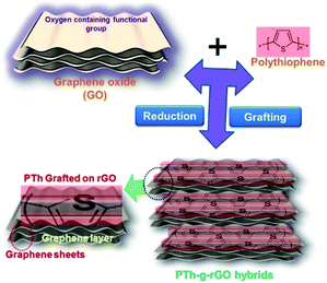
The covalent grafting of the PTh on the graphene sheets may bring the synergistic impact of both materials, where former will lead to high capacitance and, later, will improve the cycling performance due to its high conductivity. Here, we have covalently grafted the PTh on the oxygen rich graphene oxide sheets by esterification reactions and oxidative polymerization. A schematic representation for the synthesis process of the PTh-g-rGO hybrid is shown in Fig. 1, including grafting of conducting polymer and simultaneous reduction of graphene oxide. The polythiophene was not only grafted but also led to the reduction of graphene oxide sheets at room temperature, thus improved the conductivity of the hybrids.15 When tested as a pseudocapacitive electrodes, high capacitance and excellent capacitance retention of 100% was observed after 5000 cycles at 50 mV s−1.
 | ||
| Fig. 1 Schematic presentation of the simultaneous reduction and covalent grafting of the thiophene derivative on graphene oxide sheets. | ||
Graphene oxide used to graft PTh was synthesized by modified Hummer's method, as described previously.16 First, 100 mg of graphene oxide (GO) was dispersed in 10 mL DMF using bath sonication up to 30 minutes to obtain a homogeneous solution of the GO. Further, 500 mg of 3-thiophene acetic acid (3.5 mmol) in 5 mL DMF was added to the GO solution and stirred for further 30 min. A solution of DCC (725 mg, 3.5 mmol) and DMAP (43 mg, 0.35 mmol) in 5 mL of DMF was prepared separately and added into the reaction mixture of the graphene oxide and TAA and the reaction mixture was allowed to stir for 48 h under inert atmosphere at 25 °C. After the completion of the reaction, 100 mL DMF was added to solutions and the product was obtained by vacuum filtration. Further, functionalized GO was washed with plenty of DMF and methanol and dried at 40 °C under vacuum. Further 100 mg of TAA grafted GO was sonicated in a 10 mL of dry chloroform for 25 min to obtain the homogenous solution. Later, 40 mg of ferric chloride in 10 mL of chloroform was added to the solution, and the reaction mixture was stirred at room temperature for 24 h to complete the chemical oxidative polymerization process.17 The polythiophene (PTh) grafted GO was obtained after vacuum filtration and drying at 40 °C under vacuum. Surface morphologies of the samples were probed by transmission electron microscopy (TEM, JEOL JEM-2100, Japan) with an accelerating voltage of 200 kV and scanning electron microscope (SEM, Carl Zeiss AG, Germany) operating at 3 kV. The changes in the surface chemical bonding were characterized by Fourier transform infrared (FTIR) (Thermo Nicolet Nexus) operating in transmission mode (8 cm−1, 32 scans per spectrum). The Raman spectrum of the as synthesized samples were recorded by Raman spectrometer Renishaw inVia spectrometer with a 632 nm laser as excitation source. Film electrodes were prepared by mixing 90 wt% active material with 5 wt% carbon black (Alfa Aesar, USA) and 5 wt% polytetrafluoroethylene (PTFE) binder (Sigma-Aldrich) in ethanol. After evaporation of ethanol, the powder was rolled into 50 μm film. The activated carbon electrodes (150 μm) were prepared by mixing 95 wt% AC and 5 wt% PTFE binder. All electrochemical tests were performed in a three-electrode Swagelok® cell. GO or PTh-g-rGO were used as the working electrode, activated carbon films were used as the counter electrode, and Ag/AgCl was used as the reference electrode. A Celgard membrane served as a separator and 1 M H2SO4 as the electrolyte solution. Cyclic voltammetry (CV), galvanostatic charging/discharging, and electrochemical impedance spectroscopy (EIS) were used to study electrochemical performance of the hybrids.
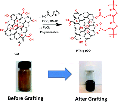
The PTh-g-rGO hybrid was synthesized via chemical oxidative polymerization process (Fig. 2). In this process, the monomer was added to the GO dispersion in DMF, and the color of the reaction mixture was monitored. The brown color dispersion of GO was turned into dark black color, indicating the reduction of the graphene oxide and initiation of the polymerization process. The synthesis of PTh-g-rGO hybrids was carried out in two steps. In the first step, the monomer was grafted with GO by the esterification reaction followed by oxidative polymerization in the second step. It is worthy to point out that reduction of the GO happened at room temperature, in contrast to previous reports where high temperature for the extended period of time is needed. The proposed the reduction mechanism of the GO by thiophene, which could be useful for other applications. It is likely that the reduction mechanism involves donation of electrons from thiophene monomers to reduce GO to rGO during their polymerisation into the oxidised form.15
 | ||
| Fig. 2 Reaction scheme of covalent grafting of the polythiophene derivative on graphene oxide sheets. | ||
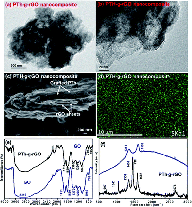
The TEM images (Fig. 3a and b) display a uniform grafting of the rGO sheets by PTh without any apparent agglomeration. The overlaps and corrugation features of the hybrids occurred because of the high aspect ratio of the nanosheets. The SEM analysis (Fig. 3c) shows that PTh and rGO are interconnected with each other via covalent bonding (Fig. 2) and formed a sandwich like structure. The PTh-g-rGO hybrids display a compact layered sheet structure, which permits facile access of the electrolyte ions. Furthermore, the uniform coating of the PTh on the conductive rGO sheets permits fast electronic transport which guarantees good electrochemical behavior.
Energy-dispersive X-ray spectroscopy (EDS) elemental mapping of the bulk PTh-g-rGO was used to identify the spatial distribution of the elemental composition (Fig. S1†). The EDS mapping (Fig. 3d) of dark green (sulphur) underpins the fact that PTh was uniformly grafted on rGO sheet. The EDS maps of sulfur (dark green) showed the presence of sulfur (3.07 at%), carbon (72.05 at%) and (d) oxygen (24.88 at%).
The FTIR spectrum of GO (Fig. 3e) displays broad and intense peak centered at 3365 cm−1 attributed to the –OH stretching vibration. The peaks at around 1225 and 1045 cm−1 can be attributed to stretching vibration of epoxy and alkoxy groups. The sharp peak at 1711 and broad peak at 1370 cm−1 are the C![[double bond, length as m-dash]](https://www.rsc.org/images/entities/char_e001.gif) O stretching vibration adsorption peaks of carboxyl and carbonyl groups. The sharp and narrow peak at 1620 cm−1 is ascribed to the stretching vibration of aromatic C
O stretching vibration adsorption peaks of carboxyl and carbonyl groups. The sharp and narrow peak at 1620 cm−1 is ascribed to the stretching vibration of aromatic C![[double bond, length as m-dash]](https://www.rsc.org/images/entities/char_e001.gif) C bonds. The other peak at 769 cm−1 is due to the C–H bonds.18 These peaks evidence shows the existence of different abundance functional groups such as epoxy, hydroxyl, carboxyl and carbonyl on the GO surfaces which has been utilized as active sites to grafting the PTh.19
C bonds. The other peak at 769 cm−1 is due to the C–H bonds.18 These peaks evidence shows the existence of different abundance functional groups such as epoxy, hydroxyl, carboxyl and carbonyl on the GO surfaces which has been utilized as active sites to grafting the PTh.19
Moreover, comparison of the spectra of GO and PTh-g-rGO hybrids shows a dramatic decrease in intensity of the absorption peaks of oxygen-containing functional groups (1711, 1045 cm−1), which indicates GO reduction in rGO in PTh-g-rGO hybrids. The one new peak at lower wavenumber side at 695 cm−1 corresponds to C–S stretching in the thiophene ring which is due to PTh in PTh-g-rGO hybrid.20,21 The overall FTIR observation confirms that GO converted into rGO and also successfully covalently incorporated in the PTh matrix in the PTh-g-rGO hybrids.
Raman spectroscopy of GO and PTh-g-rGO hybrids materials was carried out to investigate the possible interactions of PTh with rGO. Raman spectra have been commonly used to characterize the structural information of sp2 carbon materials and reveal the quality of synthesized sample in terms of graphene layers, degree of defects and various doping level.22 The Raman spectra of GO and PTh-g-rGO hybrids are shown in Fig. 3f. The Raman spectrum of the GO shows two characteristic peaks at 1341 and 1599 cm−1 that correspond to the D and G bands, respectively.19,22 The Raman spectra of PTh-g-rGO hybrids show several sharp peaks at 697, 1043, 1334, 1451, 1587 and 2676 cm−1. Among the above peaks, the two peaks as 1334 and 1587 shows the D band and G band, respectively in PTh-g-rGO hybrids due to rGO. It can be seen that the both (G and D band) bands are shifted towards lower wave number side, which shows the red shifting in PTh-g-rGO hybrids. This shifting in G and D bands is mainly due to the charge-transfer interaction and π–π interaction between thiophene rings of PTh with rGO.23 Furthermore, the ID/IG decreased in PTh-g-rGO hybrids from 0.91 (GO) to 0.72, which is due to the reduction of GO to rGO in PTh-g-rGO hybrids. The other peak at 697, 1043 and 1451 cm−1 corresponds to the Cα–S–Cα deformation, Cβ–H bending and Cα![[double bond, length as m-dash]](https://www.rsc.org/images/entities/char_e001.gif) Cβ ring stretching, respectively due to presence of thiophene in PTh-g-rGO hybrids.24,25 The graphene oxide is an insulator, however, the PTh-g-rGO hybrid showed the conductivity of approximately 1.0 S m−1 via four probe measurement, which is also supporting the reduction as well as grafting.
Cβ ring stretching, respectively due to presence of thiophene in PTh-g-rGO hybrids.24,25 The graphene oxide is an insulator, however, the PTh-g-rGO hybrid showed the conductivity of approximately 1.0 S m−1 via four probe measurement, which is also supporting the reduction as well as grafting.
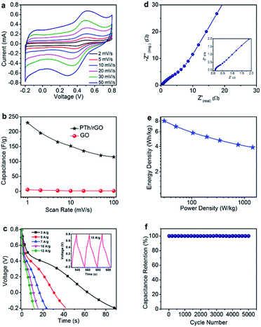
Electrochemical measurement like CV of PTh-g-rGO hybrids was performed in potential window between −0.2 and 0.8 V at different scan rates of 5, 10, 20, 30, 40, and 50 mV s−1 (Fig. 4a). At lower scan rates, the shapes of the CV curves indicate that their capacitive characteristics are similar to that of electrical double layer capacitor (EDLC) for which the CV curve resembles to a nearly rectangular shape which is typical behavior for graphene-based supercapacitors. The peak current increases progressively with increasing scan rate. But at higher scan rates we observe that the signal has both characteristics as EDLC and faradaic processes associated with a pseudocapacitor. The specific capacitances of the PTh-g-rGO hybrids electrodes were calculated similar to reported work.26
Fig. 4b shows the specific capacitance of PTh-g-rGO hybrids at different scan rates. The specific capacitances evaluated from the CV curves for PTh-g-rGO hybrids were found to be 230, 195, 165, 152, 135, 120 and 115 F g−1 at scan rates of 1, 2, 5, 10, 20, 50 and 100 mV s−1, respectively. The decrease in specific capacitance with increasing scan rates can be attributed to the fact that the electrolyte ions are not fully accessible to the interior surfaces of the active materials for charge-storage because of the reduced diffusion time at a high scan rate. It can be seen that the electrode materials, PTh-g-rGO hybrids showed the maximum specific capacitance of 230 F g−1 at a scan rate of 1 mV s−1, whereas pure GO, exhibit very low specific capacitance (5 F g−1 at 1 mV s−1), at the same scan rate. Fig. 4b shows that the specific capacitance PTh-g-rGO hybrids which are 46 times higher than the pure GO. In situ reduction of GO by thiophene not only enhance the surface area of rGO but also improved the conductivity after removal the functional groups such as epoxy, hydroxyl, carboxyl and carbonyl from GO surfaces. This enhanced surface area and conductivity of rGO in PTh-g-rGO hybrids are the most likely reasons for the high specific capacitance. The uniformly dispersed conducting polymer in rGO not only effectively inhibit the stacking and agglomeration of GO, resulting in high capacitance but also provides a highly conductive network for electron transport during the CV processes.
The excellent interfacial contact between PTh and rGO can significantly improve the accessibility of PTh-g-rGO hybrids to the electrolyte ions and shorten the ion diffusion and migration pathways. Meanwhile, the ion transfer paths are largely shortened because PTh-g-rGO hybrids have thick sheet like structure. All these factors led to improved capacitance.
Galvanostatic charge/discharge behavior of the PTh-g-rGO hybrids (Fig. 4c) electrode at different current densities of 3, 5, 7, 10, 12 and 15 A g−1 showed an increase in discharge time at low current densities due to better percolations of the ions and vice versa. Inset of the Fig. 4c shows the charge/discharge profile of PTh-g-rGO hybrids measured at a current density of 10 A g−1 which exhibited almost symmetric triangular shape with no obvious ohmic drop, indicating the negligible internal resistance and good columbic efficiency.27 Nyquist plot of PTh-g-rGO hybrids (Fig. 4d) shows a straight line in the low-frequency region and a very small arc in the high frequency region. The intersection of the real axis in high-frequency region represents the solution resistance and is related to the charge transfer between the electrode materials and electrolyte.28–31 It is seen that the PTh-g-rGO hybrids have a very low solution resistance of 0.14 Ω, suggesting good electronic conductivity of the hybrids. Furthermore, negligible semicircle indicate minimal charge-transfer resistance (Rct) which ensures better charge percolation during charging/discharging. The low charge-transfer resistance and negligible semicircle further indicate good integration of PTh onto rGO sheets which exhibited low Warburg diffusion resistance. The interlinked grafting structure of PTh-g-rGO hybrids facilitates the fast electrolyte ion transport during the electrochemical processes and provides a continuous conductive network. Ragone plot (Fig. 4e) shows that the PTh-g-rGO hybrids exhibited high energy density of 8 W h kg−1 in aqueous 1 M H2SO4 electrolyte.
It is well-known that long-term cyclic stability is a significant consideration for the practical application of a material in a supercapacitor electrode. The cycling stability of the hybrids was measured using CV technique at a scan rate of 50 mV s−1 up to 5000 cycles (Fig. 4f). The nearly 100% capacitance retention was observed which again confirmed the usefulness of the covalent grafting and is a future guideline for the synthesis of supercapacitor hybrids. The achieved long term stability and retention properties of as synthesized PTh-g-rGO hybrids shows better performance than the works reported by others on carbon materials with different polymers based supercapacitors.32–39 It shows that our hybrids have outperformed reports in cycling stability due to covalent network and synergic contribution of the polythiophene and reduced graphene oxide sheets.
Conclusions
In conclusion, we have shown simultaneous reduction and covalent grating of thiophene derivatives on GO sheets to synthesize PTh-g-rGO hybrid by a simple and inexpensive in situ chemical oxidative polymerization method. The SEM images showed uniform coating of the two-dimensional rGO sheets. The Raman and FTIR spectroscopies confirmed the strong interaction of PTh with rGO in the PTh-g-rGO hybrids. The formation of such a special type of morphology enhances the electrochemical properties of the PTh-g-rGO hybrids. Such two-dimensional morphology provide facile ionic and electronic transport for better electrochemical performance. The maximum specific capacitance of 230 F g−1 (1 mV s−1) was obtained for the PTh-g-rGO hybrids. Most important, the PTh-g-rGO hybrid showed the excellent stability without distorted and degradation nature of CV even after 5000 cycles and capacitance retention ration of 100%, which indicating excellent stability. Based on the results, the PTh-g-rGO hybrids can be used as electrode material for high-performance supercapacitor electrodes.Acknowledgements
We would like to gratefully acknowledge anonymous referees for useful comments and constructive suggestions.Notes and references
- B. Xu, S. Yue, Z. Sui, X. Zhang, S. Hou, G. Cao and Y. Yang, Energy Environ. Sci., 2011, 4, 2826–2830 CAS.
- F. Beguin, E. Frackowiak and M. Lu, Supercapacitors: Materials, Systems and Applications, Wiley-VCH, 1st edn, 2012 Search PubMed.
- V. Augustyn, P. Simon and B. Dunn, Energy Environ. Sci., 2014, 7, 1597 CAS.
- R. Kumar, H.-J. Kim, S. Park, A. Srivastava and I.-K. Oh, Carbon, 2014, 79, 92–202 CrossRef.
- R. Kumar, R. K. Singh, P. K. Dubey, D. P. Singh, R. M. Yadav and R. S. Tiwari, Adv. Mater. Interfaces, 2015 DOI:10.1002/admi.201500191.
- M. Wang, R. Jamal, Y. Wang, L. Yang, F. Liu and T. Abdiryim, Nanoscale Res. Lett., 2015, 10, 370 CrossRef PubMed.
- M. Boota, M. P. Paranthaman, A. K. Naskar, Y. Li, K. Akato and Y. Gogotsi, ChemSusChem, 2015, 8, 3576–3581 CrossRef CAS PubMed.
- D. Vonlanthen, P. Lazarev, K. A. See, F. Wudl and A. J. Heeger, Adv. Mater., 2014, 26, 5095–5100 CrossRef CAS PubMed.
- F. Bonaccorso, L. Colombo, G. Yu, M. Stoller, V. Tozzini, A. C. Ferrari, R. S. Ruoff and V. Pellegrini, Science, 2015, 347, 1246501 CrossRef PubMed.
- S. Park and R. S. Ruoff, Nat. Nanotechnol., 2009, 4, 217–224 CrossRef CAS PubMed.
- S. K. Yadav, H. J. Yoo and J. W. Cho, J. Polym. Sci., Part B: Polym. Phys., 2013, 51, 39–47 CrossRef CAS.
- N. A. Kumar, H.-J. Choi, Y. R. Shin, D. W. Chang, L. Dai and J.-B. Baek, ACS Nano, 2012, 6, 1715–1723 CrossRef CAS PubMed.
- G. A. Snook, P. Kao and A. S. Best, J. Power Sources, 2011, 196, 1–12 CrossRef CAS.
- S. Nejati, T. E. Minford, Y. Y. Smolin and K. K. S. Lau, ACS Nano, 2014, 8, 5413–5422 CrossRef CAS PubMed.
- S. Some, Y. Kim, Y. Yoon, H. Yoo, S. Lee, Y. Park and H. Lee, Sci. Rep., 2013, 3, 1929 Search PubMed.
- J. William, S. Hummers and R. E. Offeman, J. Am. Chem. Soc., 1958, 80, 1339 CrossRef.
- M. S. Ramasamy, S. S. Mahapatra, H. J. Yoo, Y. A. Kim and J. W. Cho, J. Mater. Chem. A, 2014, 2, 4788–4794 CAS.
- S. K. Yadav and J. W. Cho, Appl. Surf. Sci., 2013, 266, 360–367 CrossRef CAS.
- M. Boota, K. B. Hatzell, M. Alhabeb, E. C. Kumbur and Y. Gogotsi, Carbon, 2015, 92, 142–149 CrossRef CAS.
- M. G. Han and S. H. Foulger, Adv. Mater., 2004, 16, 231–234 CrossRef CAS.
- M. R. Karim, K. T. Lim, C. J. Lee and M. S. Lee, Synth. Met., 2007, 157, 1008–1012 CrossRef CAS.
- Y. Zhu, S. Murali, W. Cai, X. Li, J. W. Suk, J. R. Potts and R. S. Ruoff, Adv. Mater., 2010, 22, 3906–3924 CrossRef CAS PubMed.
- P. Sivaraman, A. R. Bhattacharrya, S. P. Mishra, A. P. Thakur, K. Shashidhara and A. B. Samui, Electrochim. Acta, 2013, 94, 182–191 CrossRef CAS.
- G. Louarn, J. Kruszka, S. Lefrant, M. Zagorska, I. Kulszewicz-Bayer and A. Proń, Synth. Met., 1993, 61, 233–238 CrossRef CAS.
- R. Pokrop, I. Kulszewicz-Bajer, I. Wielgus, M. Zagorska, D. Albertini, S. Lefrant, G. Louarn and A. Pron, Synth. Met., 2009, 159, 919–924 CrossRef CAS.
- C. Zhang, K. B. Hatzell, M. Boota, B. Dyatkin, M. Beidaghi, D. Long, W. Qiao, E. C. Kumbur and Y. Gogotsi, Carbon, 2014, 77, 155–164 CrossRef CAS.
- M. Boota, B. Anasori, C. Voigt, M. Zhao, M. W. Barsoum and Y. Gogotsi, Adv. Mater., 2016, 28, 1517–1522 CrossRef CAS PubMed.
- P. L. Taberna, P. Simon and J. F. Fauvarque, J. Electrochem. Soc., 2003, 150, A292 CrossRef CAS.
- M. Boota, K. B. Hatzell, M. Beidaghi, C. R. Dennison, E. C. Kumbur and Y. Gogotsi, J. Electrochem. Soc., 2014, 161, A1078–A1083 CrossRef CAS.
- M. Boota, C. Chen, M. Becuwe, L. Miao and Y. Gogotsi, Energy Environ. Sci., 2016 10.1039/x0xx00000x.
- M. Boota, K. B. Hatzell, E. C. Kumbur and Y. Gogotsi, ChemSusChem, 2015, 8, 835–843 CrossRef CAS PubMed.
- N. A. Kumar, H. J. Choi, A. Bund, J.-B. Baek and Y. T. Jeong, J. Mater. Chem., 2012, 22, 12268–12274 RSC.
- Y. Gui, X. Xing and C. Song, Mater. Chem. Phys., 2015, 167, 330–337 CrossRef CAS.
- A. Di Fabio, A. Giorgi, M. Mastragostino and F. Soavi, J. Electrochem. Soc., 2001, 148, A845–A850 CrossRef CAS.
- J. Zhang and X. S. Zhao, J. Phys. Chem. C, 2012, 116, 5420–5426 CAS.
- H. Zhou, W. Yao, G. Li, J. Wang and Y. Lu, Carbon, 2013, 59, 495–502 CrossRef CAS.
- C. Fu, H. Zhou, R. Liu, Z. Huang, J. Chen and Y. Kuang, Mater. Chem. Phys., 2012, 132, 596–600 CrossRef CAS.
- N. Lingappan, D. W. Kim, X. T. Cao, Y.-S. Gal and K. T. Lim, J. Alloys Compd., 2015, 640, 267–274 CrossRef CAS.
- E. Frackowiak, V. Khomenko, K. Jurewicz, K. Lota and F. Béguin, J. Power Sources, 2006, 153, 413–418 CrossRef CAS.
Footnote |
| † Electronic supplementary information (ESI) available: Fig. S1. See DOI: 10.1039/c6ra07904k |
| This journal is © The Royal Society of Chemistry 2016 |


