
Sealing of tartaric sulfuric (TSA) anodized AA2024 with nanostructured LDH layers
B. Kuznetsova,
M. Serdechnova *b,
J. Tedimc,
M. Starykevichc,
S. Kallipc,
M. P. Oliveirac,
T. Hackd,
S. Nixond,
M. G. S. Ferreirac and
M. L. Zheludkevichbc
*b,
J. Tedimc,
M. Starykevichc,
S. Kallipc,
M. P. Oliveirac,
T. Hackd,
S. Nixond,
M. G. S. Ferreirac and
M. L. Zheludkevichbc
aBelarusian State University, Faculty of Chemistry, 4, Nezavisimosti avenue, 220030, Minsk, Belarus
bInstitute of Materials Research, Helmholtz-Zentrum Geesthacht, Max-Planck-Straβe 1, 21502 Geesthacht, Germany. E-mail: maria.serdechnova@hzg.de
cDepartment of Materials and Ceramic Engineering, CICECO – Aveiro Institute of Materials, University of Aveiro, 3810-193 Aveiro, Portugal
dAirbus Group Innovations, 81663 Munich, Germany
First published on 28th January 2016
Abstract
In this work, a functional sealing of a TSA anodic layer on AA2024 is suggested based upon the formation of inhibitor-containing Zn–Al layered double hydroxides (LDH). The LDH structures are formed in the pores of the anodic layer and on top of it as a result of hydrothermal treatment in a Zn2+-containing bath as shown by the structure, morphology and composition analysis. The resulting LDHs were loaded with a well-known corrosion inhibitor (vanadate). Electrochemical impedance spectroscopy, salt spray tests and scanning vibrating electrode techniques have shown a remarkable improvement in corrosion resistance of the LDH-modified sample in comparison with conventional hot-water sealing. The vanadate-loaded LDHs rendered a significant long-term active protection for the covered aluminum alloy substrate.
1. Introduction
For decades the active corrosion protection for most of the technical metallic substrates was achieved using chromate-based surface treatments or Cr(VI)-derived anti-corrosion pigments integrated into organic polymer coatings. In this regard, the aerospace industry was no exception, and the use of chromic acid anodizing (CAA) had been the preferential choice for developing pre-treatment layers in high strength aluminum alloys, as it rendered corrosion resistance without compromising damage tolerance.1,2 Nevertheless, the high toxicity associated with Cr(VI) species led to replacement by more environmentally-friendly anodizing electrolytes such as one based on tartaric/sulfuric acid (TSA).3,4 This is an alternative method to anodize parts through an electrolytic process with low environmental impact. It was reported that tartaric acid (C4H6O6) in the acid bath reduces the growth rate of the porous oxide film during TSA anodizing without significantly affecting the mechanism of the porous film formation.5 TSA and other sulfuric acid treatments are still challenging alternatives since they are more sensitive to the anodizing conditions when compared to CAA. The resulting oxide can be attacked depending on the time the specimens stay immersed in the electrolyte after current interruption or if there is accumulation of electrolyte within the cavities of complex geometries where rinsing is challenging.4 Other difficulties are associated with the presence of alloying elements and secondary phases which cause oxygen generation and differentiated film growth rates between the matrix and secondary phases, thereby affecting the anodic oxide morphology.6 Although acceptable corrosion resistance has been reported for TSA in most of the cases it has to be sealed in order to achieve acceptable barrier properties.In this work we propose a strategy to replace the conventional boiling water sealing of pores by a step which confers active corrosion protection to the anodic layer, with the formation of layered double hydroxides (LDHs) on the anodizing layer.7 Reports, available in the literature, show that pore sealing of anodized specimens is sensitive to the presence of acid traces and that different corrosion properties can be found for different sulfuric acid anodizing treatments.8 More relevant, in another work by García-Rubio et al.9 different post-treatments were performed on tartaric/sulfuric anodic films. Results showed that dichromate sealing avoided barrier layer degradation of the anodic layer and offered the active protection effect thanks to inhibiting Cr(VI)-species enclosed in the pores.9 These works highlight the need for environmentally friendly active corrosion protection functionality to achieve acceptable performance.
LDH has been widely studied as component of possible environmentally-friendly protective treatments for metallic materials both in form of layers10–13 and being incorporated into the protective coatings as an inhibiting pigments.14 LDHs are typically composed of positively-charged mixed metal MII–MIII hydroxide layers and interlayers occupied by anions (Ay−) and water molecules.15 The general formula of the most common LDHs can be represented as [MII1−xMIIIx(OH)2]x+(Ay−)x/y·zH2O.16,17 The protective action of LDHs loaded with inhibiting anions is based on the anion-exchange reaction induced by particular triggers, such as a change in pH and/or an appearance of corrosion-relevant anions. When corrosion conditions occur, the LDH nanocontainers (a) release inhibiting anions, while (b) absorbing corrosion-active ions such as Cl− (ref. 18–20) and/or (c) interacting with cathodically formed hydroxyl ions.21,22
In some recent studies, LDH films have been prepared in situ on bare aluminum alloys10,23,24 for the purpose of corrosion protection. The metallic substrate was immersed in a suitable M2+ containing solution and the film consisting of M2+ from the solution and M3+ from the substrate was formed on the surface. These formed LDH was used as a promising nanocontainer for incorporation/encapsulation of corrosion inhibitors.15,23,25,26 The main role of this LDH-based film is the storage and release of inhibitor on demand as a result of anion-exchange between inhibiting species and corrosion-relevant anions such as chloride and/or hydroxyl anions.27 Several authors reported that the intercalation of inhibiting anions (e.g. vanadate,7,28,29 etc.26,30) into the LDH matrix could provide enhanced protective action. However, in spite the promising active protection the barrier properties of such layers are normally insufficient.
Conceptually, the sealing of TSA anodic layer using in situ grown LDH looks promising to provide an enhanced combined passive/active corrosion protection. A LDH treatment may seal the pores in the anodized layer (barrier effect), imparting at the same time active corrosion protection via release of corrosion inhibitor when aggressive species reach the pores. In this work, we developed a LDH-based sealing method for the TSA anodized 2024 aluminum alloy (Fig. 1). Vanadates were selected as corrosion inhibitor for AA2024, intercalated into LDH galleries via anion-exchange reaction. The structure and morphology of the LDH layer was investigated by using scanning electron microscopy, X-ray diffractometry and glow discharge optical emission spectroscopy. Electrochemical impedance spectroscopy and scanning vibrating electrode techniques have been used in order to evaluate the corrosion behavior of the systems.
 | ||
| Fig. 1 The schematic representation of anodized layer sealed with LDH loaded with inhibitor. | ||
2. Experimental
2.1 Materials
The substrate was 2024-T3 aluminum alloy with following nominal composition in wt%: Cu 3.8–4.9, Fe 0.5, Cr 0.1, Mg 1.2–1.8, Mn 0.3–0.9, Si 0.5, Ti 0.15, Zn 0.25, other 0.15, Al balance.Following chemicals were used in this work: zinc nitrate hexahydrate (Zn(NO3)2·6H2O, ≥99.0%, Sigma-Aldrich, Croatia), ammonium nitrate (NH4NO3, ≥99.0%, Sigma-Aldrich, Germany), ammonia solution (NH3·H2O, 25% Fluka, Germany), sodium metavanadate anhydrous (NaVO3, 99.9% Sigma-Aldrich, USA), sodium nitrate (NaNO3, ≥99.5% Sigma-Aldrich, Germany), sodium chloride (NaCl, ≥99.8%, Sigma-Aldrich, Denmark), DL-tartaric acid (≥99%, Sigma-Aldrich, India), sulfuric acid (H2SO4 95–98%, Alfa Aesar, Germany) and acetone (for analysis-ACS, Carlo Erba reagents). Deionized water was used as a solvent.
2.2 Procedures
Before the anodizing procedure, aluminum specimens were degreased with acetone, dried with air, clean and etched according to the standard commercial procedure (alkaline cleaning in Metaclean T2001 at 68 °C for 25 min, alkaline etching in Turco Liquid Aluminetch N2 at 60 °C for 45 s, acid etching in Turco Liquid Smutgo NC at 30 °C for 7 min each followed by washing in deionized water).31 The anodizing process was performed in a tartaric/sulfuric acid bath (0.53 M C4H6O6, 0.46 M H2SO4) at 37 °C and carried out at 14 V for 25 min. These parameters were used in order to obtain a layer thickness of about 3 μm. The stainless steel sheets were used as the cathodes during the anodization. After the anodizing step, the specimens were rinsed with deionized water, dried under air conditions and used in one of the following treatments.(1) LDH-nitrate sealing (called as LDH-NO3). Zn(NO3)2·6H2O (0.01 mol) and NH4NO3 (0.06 mol) were dissolved in deionized water (100 ml). Then, under vigorous stirring, the pH of the solution was adjusted up to 6.5 by slowly adding of 1% ammonia. The anodized specimens were placed in the obtained solution at 95 °C for 30 minutes under continuous stirring. After this time specimens were rinsed with deionized water and dried under air conditions at room temperature. This treatment led to formation of parental LDH structures with nitrate anion. Nitrates were used in the parental LDH due to their ability to be relatively easy replaced by corrosion inhibitors in the interlayer in the consecutive steps.
(2) LDH-vanadate sealing (called as LDH-VOx) the LDH-vanadate sealing was achieved via anion-exchange reaction from the parental LDH-nitrate structure. For the anion-exchange reaction 0.1 M NaVO3 solution (pH 8.4) was prepared. Since the structure of “vanadate” ions from NaVO3 in aqueous solution at pH = 8.4 could be presented as [VO3−]n (where n = 3, 4)32 the general formula LDH-VOx is used in this work. The specimens covered with parental LDH were immersed in this solution at 50 °C for 30 and 60 minutes (indicated in the specification of relative samples). After the exchange, the samples were rinsed with deionized water and dried at room temperature under air conditions.
(3) Hot water sealing (HWS) of anodized AA2024 samples without LDHs was used as a reference. The anodized specimens were placed in boiling deionized water for 30 min. After treatment the samples were dried under air conditions at room temperature.
2.3 Techniques
Electrochemical impedance spectroscopy (EIS) measurements were carried out in a three-electrode cell consisting of a saturated calomel reference electrode, a platinum foil as a counter electrode and a sample as a working electrode with a horizontal position and an exposed area of approximately 3 cm2. The cell was placed in a Faraday cage to avoid any interference with external electromagnetic fields. The EIS measurements were performed using a Gamry FAS2 Femtostat at room temperature in a naturally aerated 0.05 M NaCl solution. Impedance measurements were performed over frequency range between 105 and 10−1 Hz, with 7 points per decade. All the spectra were recorded versus open circuit potential with applied 10 mV RMS sinusoidal perturbation. The experimental impedance plots were fitted using different equivalent circuits by means of the Echem Analyst software from Gamry.Scanning electron microscopy (SEM) observations coupled with energy dispersive analysis (EDS) were performed on Hitachi S-4100 system with electron beam energy of 25 keV.
X-ray diffraction (XRD) patterns were obtained using Rigaku D/Max-B diffractometer (Cu Kα radiation) with step 0,02° and exposition time about 200 s per step) at room temperature.
Glow discharge optical emission spectroscopy (GDOES) depth profile analysis of the coatings was performed using a HORIBA GD-Profiler 2 with an anode of 4 mm in diameter and operating at a pressure of 650 Pa and at power of 30 W.
Scanning vibrating electrode technique (SVET) measurements were performed using Applicable Electronics Inc. (USA) instrumentation controlled by the ASET software from ScienceWares (USA). The vibrating microelectrode had a 10–20 μm spherical platinum black tip and vibrated with 20 μm amplitude in two directions (normal and parallel to surface) at an average distance of 200 μm above the surface of the sample. Artificial defects (approximately 1.8 mm length and 100 μm width) were introduced to the coatings by scalpel. The specimens were immersed in 0.05 M NaCl corrosive media. Origin 9.1 software has been used for processing the SVET maps.
Neutral salt spray test (SST) was performed according to ISO 9227 in a salt spray cabinet SC 1000 from Weiss Umwelttechnik. The samples were inclined at 20° from the vertical. The edges were masked with a masking tape to avoid corrosion at the edges. The temperature was kept constant at 35 °C. The salt fall out was recorded twice a week. Before each inspection the samples were rinsed with deionized water to remove remaining sodium chloride from the sample surface and the dried with nitrogen. The samples were inspected after 168 and 600 hours of exposure to salt spray.
3. Results and discussion
3.1 Chemical and phase composition
The composition, morphology and micro-structure of the sealed TSA specimens was studied by XRD, SEM/EDS, and GDOES methods.The XRD patterns (in the range of 5 to 25 degr.) of the TSA anodized AA2024 sample (blank), TSA anodized AA2024 sample after hot water sealing (HWS), TSA anodized AA2024 samples covered with LDH-nitrate (LDH-NO3) and with LDH-vanadate (LDH-VOx) are shown in Fig. 2. This range of angles was chosen in order to confirm the presence and crystal structure of LDHs synthesized in this work. The characterization of original TSA layer and AA2024 aluminum alloy is carefully reported in previous works.33 XRD pattern of LDH-NO3 shows well-defined peaks at 9.86° and 19.92° which could be assigned to (003) and (006) reflections of LDH.15 These reflections correspond to a basal spacing of 8.96 Å, and taking into account the thickness of the positively charged Zn/Al hydroxide layer (similar to brucite, about 4.77 Å (ref. 34)), the space available for NO3− corresponds to 4.19 Å. This is in agreement with previous reports obtained for LDH phases directly grown on AA2024.35
 | ||
| Fig. 2 X-ray diffraction patterns for sample: (a) – blank, (b) – HWS, (c) – LDH-NO3, (d) – LDH-VOx. | ||
After anion exchange reaction between LDH-NO3 with vanadates, the peak positions in the XRD pattern are shifted. Comparison of these two diffractograms clearly indicates that the gallery height increases from 4.19 Å (d(003) = 8.96 Å) to 4.81 Å (d(003) = 9.22 Å). This result is in a nice agreement with published previously and can indicate the pyrovanadate form of inhibitor inside LDH.10,36 No reflections corresponding to the parental LDH-NO3 were detected after the anion exchange reaction, thereby indicating that the exchange was complete.
No peak typical for LDH was detected for blank and HWS samples.
EDS spectra of all the samples are presented in Fig. 3. The blank and HWS samples contain mostly aluminum and oxygen (Fig. 3a and b) as expected. The LDH-NO3 surface contains aluminum, oxygen and zinc (Fig. 3c) and a vanadium signal additionally appears after the ion-exchange on LDH-VOx sample (Fig. 3d). These findings are consistent with the structural analysis performed by XRD. The HWS sample has micrometer-thick layer of aluminum oxide grown by anodizing process, therefore only aluminum and oxygen elements were expected to be found. In the case of LDH-containing samples, the presence of zinc is consistent with the presence of LDH phases, which also have aluminum and oxygen (from metal hydroxide sheets) in their composition. Finally, the sample with LDH-VOx shows the presence of vanadium, consistent with intercalation of vanadates.
 | ||
| Fig. 3 EDS spectra of the samples: (a) – blank, (b) – HWS, (c) – LDH-NO3, (d) – LDH-VOx. | ||
A similar elemental composition was found by GDOES analysis. Depth profiles of the elements across the anodic layers are presented in Fig. 4. The signal of oxygen was detected in the anodic layer with and without further treatment. At the beginning its signal is very high because of the surface contamination with entrapped and adsorbed oxygen and water (zone I), then the signal decreases and reaches a plateau attributed to the oxide sputtering (zone II) after that decreases again due to the simultaneous sputtering of anodized layer and substrate alloy (zone III) and finally reaches the noise level during the sputtering of the alloy (zone IV). Such an oxygen profile is typical for all four investigated systems.
 | ||
| Fig. 4 GDOES depth profile of samples: (a) – blank, (b) – HWS, (c) – LDH-NO3, (d) – LDH-VOx. | ||
Aluminum profile presents a relatively low level in the beginning (attributed to the hydrated layer or LDH sputtering, zone I) which increases and reaches a plateau (zone II) which can be attributed to the anodic layer sputtering, followed by a fluent increase of aluminum signal (proportional to aluminum concentration) due to the simultaneous sputtering of anodized layer and alloy (zone III) (Fig. 4). The decrease of oxygen concentration at the same time with the increasing of aluminum concentration in zone III confirms the transition from anodized layer to alloy during sputtering. Changing of the signals between anodized layer and alloy is not sharp and can be interpreted as a roughness of the substrate after pretreatment. A second plateau of the aluminum can be attributed to the sputtering of the alloy (zone IV). A signal of copper appears in zone III and has the same trend as aluminum signal and can be explained by the sputtering of copper reach phases from the alloy.
It can be seen that for HWS sample, the oxygen signal in the beginning of sputtering is higher due to the more extensive hydration of the aluminum oxide. Moreover, the plateau of oxidized aluminum layer is thicker in comparison with a blank sample. It can be explained by sealing of the porous in the anodized layer, the increase of its density and lower sputtering rate as a result. No signal of vanadium and zinc was detected for blank and HWS samples.
The LDH sealing treatment leads to appearance of a clear Zn signal on the surface of the samples both with nitrate and vanadate counter anions. The Zn signal is very high at the surface and rapidly decreases when going deeper showing the presence of a Zn-containing layer on the surface of anodic film. It can be later seen by SEM. However it is also very important that when reaching the anodic oxide surface the signal does not go immediately to zero. There is still a quite remarkable level of Zn present in the pores showing that Zn-containing products are formed in the pores as well almost reaching the oxide/metal interface not only on the surface (Fig. 4c and d).
After the ion-exchange a well-defined signal of vanadium can be seen across the layer (Fig. 4d). The maximum is observed close to the interface of anodic film, the place where main LDH-phase is concentrated. It is also very important that the vanadate penetrates down to the pores. The vanadium signal goes along the one of Zn suggesting that these two elements present in the pores can be part of the same LDH structure formed during the sealing/ion-exchange stages.
3.2 Morphology of the surface
SEM micrographs of all the samples considered in this work are shown in Fig. 5. The anodized AA2024 surface (Fig. 5a) has a porous, inhomogeneous structure. The pores in the case of TSA anodizing are usually very narrow and not visible at present magnification. After hot water treatment, the morphology of the surface changes significantly (Fig. 5b). At the microscale, the surface becomes covered with flake-like particles 0.1–0.2 μm in sizes. This is consistent with data reported in the literature37 and can be associated to formation of boehmite-like products. LDH-NO3 sealing leads to a rougher surface with a lot of large flakes (Fig. 5c). The size of these flakes can be estimated to be about 0.5–1 μm. The morphology of flakes does not change during the anionic exchange reaction of nitrate anions by vanadate ones (Fig. 5c and d). | ||
| Fig. 5 SEM micrographs of samples: (a) – blank, (b) – HWS, (c) – LDH-NO3, (d) – LDH-VOx. | ||
Thus the obtained results clearly demonstrate that suggested alternative sealing leads to formation of LDH-based structures on the surface of the anodic film. At the same time the presence of Zn and V elements in the pores of the anodic oxide presents an indirect evidence of formation of LDH in the pores as well.
3.3 EIS results
EIS was used in order to follow the evolution of the sealed samples during the immersion in the corrosive NaCl solution. Typical Bode plots for different sealed samples are presented in Fig. 6. In all three cases two well-defined relaxation processes are present on the spectra. The high frequency time constant can be ascribed to the presence of a sealed porous anodic oxide layer while the time constant at lower frequencies is associated to an inner thin barrier oxide layer. Several important differences can be encountered when comparing the behavior of the systems with different sealing. The pore resistance of the outer layer constituted by the sealed pores at the beginning of immersion is significantly higher for the boiling water sealing (HWS) when comparing to that of the systems sealed by LDH process. The lowest pore resistance is in the case of nitrate containing LDH. The impedance corresponding to the capacitance of the inner oxide is very similar for all the samples indicating comparable thickness of this layer. However the barrier properties of the inner layer are not equal and follow the same order like in the case of pore resistance of the outer layer. This behavior is only observed at short immersion times and changes significantly during longer exposure. | ||
| Fig. 6 Impedance spectra obtained on HWS, LDH-NO3 and LDH-VOx samples after 1 hour immersion in NaCl solution. | ||
The EIS measurements were performed during 4 weeks. All the spectra obtained after different immersion times were fitted using appropriate equivalent circuits which describe the physical model of the coated corroding sample. Two different equivalent circuits were used depending on the sample and its degradation level. The circuit demonstrated in Fig. 7a was applied when only two relaxation processes are present as in the case of spectra shown in Fig. 6. In this case Rsol corresponds to the resistance of electrolyte; Rpor and Rin are resistances of porous and inner oxide layers respectively; Qpor, npor and Qin, nin are the components of the constant phase elements for the same layers. The constant phase elements were used in all the circuits instead of the capacitances in order to account for non-ideal capacitive behavior which can be caused by non-uniformities in the thickness or dielectric constants across the layers. In several cases a third time constant at low frequencies was observed additionally to two described above. This time constant can be ascribed to the starting electrochemical activities at the metal/electrolyte interface. The respective equivalent circuit is shown in Fig. 7b. Rct and Qdl, ndl correspond to the charge transfer resistance and double layer constant phase element components respectively.
 | ||
| Fig. 7 Equivalent circuits used to fit the spectra obtained after different immersion times. | ||
The equivalent circuit with 3 relaxation processes (Fig. 7b) was used only in the cases when the third time constant was distinguishable at low frequencies. Fig. 8 demonstrates two examples of the spectra with two and three time constants. As one can see the Bode plots of the sample sealed with boiling water clearly shows appearance of a third relaxation process after longer immersion. This is a significant difference when compared to the initial spectrum of the same sample (Fig. 6) where only two time constants were observed. In contrast this third time constant can be hardly distinguished in the spectra of the system sealed with vanadate-containing LDH even after 4 weeks. Fig. 8 shows reasonably good quality of the fitting. Table 1 presents the values of different parameters and respective errors for both fitted spectra from Fig. 8. The presented data confirm once again that goodness of the fit and the associated errors are in an acceptable range.
 | ||
| Fig. 8 Typical Bode plots for spectra with two (4 weeks for LDH-VOx sample) and three (2 weeks for HWS sample) time constants. Solid lines demonstrate the respective fitting curves. | ||
| HWS | LDH-VOx | ||||||
|---|---|---|---|---|---|---|---|
| Rsol | 4 | ohms cm2 | Rsol | 4 | ohms cm2 | ||
| Qpor | 1.19 × 10⁻⁷ | 6.85 × 10⁻⁹ | S sn cm−2 | Qpor | 8.87 × 10⁻⁷ | 3.91 × 10⁻⁹ | S sn cm−2 |
| npor | 7.57 × 10⁻¹ | 5.10 × 10⁻³ | npor | 7.73 × 10⁻¹ | 4.00 × 10⁻³ | ||
| Rpor | 2.32 × 10⁴ | 484.5 | ohms cm2 | Rpor | 3.36 × 10⁴ | 551.1 | ohms cm2 |
| Qint | 9.47 × 10⁻⁷ | 3.24 × 10⁻⁸ | S sn cm−2 | Qint | 8.75 × 10⁻⁷ | 8.90 × 10⁻⁹ | S sn cm−2 |
| nint | 8.95 × 10⁻¹ | 1.09 × 10⁻² | nint | 8.99 × 10⁻¹ | 4.10 × 10⁻³ | ||
| Rint | 3.78 × 10⁶ | 8.48 × 10⁵ | ohms cm2 | Rint | 4.49 × 10⁷ | 4.48 × 10⁶ | ohms cm2 |
| Qdl | 8.68 × 10⁻⁷ | 2.11 × 10⁻⁷ | S sn cm−2 | ||||
| ndl | 9.36 × 10⁻¹ | 1.10 × 10⁻¹ | |||||
| Rct | 1.87 × 10⁷ | 5.28 × 10⁶ | ohms cm2 | ||||
| Goodness | 1.87 × 10⁻³ | Goodness | 2.90 × 10⁻³ | ||||
The values of resistance of the inner and porous layers obtained from the fitting of respective spectra for all three systems are plotted in Fig. 9. The pore resistance of the layer formed by the boiling water sealing shows the highest values when compared to that of other two systems at the initial stages of the immersion. The pore resistance in this case stays relatively stable during 4 weeks with only relatively minor decrease. The behavior of the LDH-sealed outer layer is remarkably different. The initial pore resistance is by almost an order of magnitude lower for LDH-vanadate sealing and almost two orders below the LDH-nitrate system. However in course of immersion the pore resistance of the both LDH-sealed outer layers is significantly increased reaching the values above those for HWS system by the end of long term immersion test. This behavior suggests that the LDH-sealing significantly evolves in the pores of anodic film leading to better blocking of ionic transport through the layer. Even more importantly the evolution of the resistance of the inner barrier layer demonstrates a similar trend. The resistance of the barrier layer of the boiling water sealed sample decreases by almost hundred times during 4 weeks. Moreover the low frequency time constant responsible for corrosion activities appears after around one week of test. The resistance of barrier layer for LDH-sealed system increases. The highest value is achieved in the case of the LDH sealing with vanadate corrosion inhibitor. The inner dense oxide layer is the last barrier for the electrolyte before reaching the metal surface. Therefore the resistance of this layer is of primer importance for the total corrosion performance of the coated system. The increase of the inner layer resistance suggests improvement of protection during the corrosion test. Such behavior is often assigned to the self-healing properties of the coating. However the presented EIS results do not clarify whether this effect is associated to the active protection mechanism ensured by the LDH treatment or it is related to the self-sealing effect. In the last case the active corrosion protection will not be functioning when artificial defects are formed. Therefore the scanning vibrating electrode technique was employed in order to observe the localized corrosion processes and kinetics at micro-scale artificial defects areas for all sealed coatings.
 | ||
| Fig. 9 Evolution of resistance of porous and inner layers of different sealed systems with immersion time. | ||
The EIS results are in good accordance with visual observation of the samples as shown on optical photographs taken after 4 week of immersion in 0.05 M NaCl (Fig. 10). Anodized AA2024 sample (Fig. 10a) is completely corroded and covered with a significant layer of corrosion products. In the cases of HWS, LDH-nitrate, LDH-vanadate samples no defects were visually observed. Only slight darkening of the specimens is evident due to the formation of a passive oxide layer.
 | ||
| Fig. 10 Photographs of samples after 4 week immersion in 0.05 M NaCl (a) – blank, (b) – HWS, (c) – LDH-NO3, (d) – LDH-VOx. | ||
3.4 SVET results
SVET method was used here in order to verify if the improvement of the corrosion protection performance observed by EIS on LDH-sealed TSA is related to the increase of the barrier properties or also has an important active protection component. Additional samples with increased ion-exchange time were prepared for these experiments in order to ensure that the loading with vanadate into LDH structures has a significant level for inhibition of artificial defects and can ensure self-healing effect.Fig. 11 presents the microphotographs and SVET maps taken in 0.05 M NaCl after 2 h, 12 h and 24 hours for HWS sample (Fig. 11a) and for the anodized sample covered with LDH-NO3 (Fig. 11b) and LDH-VOx treated in the vanadate solution during 30 and 60 minutes (Fig. 11c and d, respectively).
 | ||
| Fig. 11 Microphotographs, SVET profiles and projection for the samples with HWS (a), LDH-NO3 (b), LDH-VOx (30 minutes vanadate treatment) (c) and LDH-VOx (60 minutes vanadate treatment) (d) treatment at 2, 12 and 24 hours of immersion in 0.05 M NaCl corrosive media. | ||
The well-defined cathodic and anodic ionic currents are both recognized in the defect zones of all samples. The anodic currents are mainly generated by the flux of cations formed by metal dissolution:
| Al → Al3+ + 3e− | (1) |
And the cathodic currents result from the following reduction reactions:
| O2 + 2H2O + 4e− → 4OH− | (2) |
| 2H2O + 2e− → 2OH− + H2 | (3) |
It can be also noticed that due to the localized nature of AA2024 corrosion38 the anodic activity is concentrated usually at one or two more pronounced zones in the frames of defined scratch defect, but cathodic activity is more equally distributed on the residual areas. In the case of HWS sample (Fig. 11a) the corrosion activities are quite high since the initial phase of immersion and reach 29.1 μA cm−2 after one day. The activities on the sample sealed with LDH-NO3 also peaks at the high value of anodic corrosion at 20.7 μA cm−2 (Fig. 11b), while the sample treated with LDH-VOx during 30 minutes stays at 13.6 μA cm−2 after 24 hour of exposition in NaCl (Fig. 11c). The significant improvement has been achieved with increasing the sample treatment time with LDH-VOx up to 60 minutes. In the Fig. 11d the respective SVET maps show only negligible corrosion activities compared with the other samples, with maximal anodic current rising only up to 4.6 μA cm−2 after 24 h of immersion. These results are in a good agreement with literature,30 confirming that vanadate acts as an effective inhibitor for AA2024 alloy. During the immersion of the defected sample the vanadate is released from the LDH by ion-exchange with present chlorides and ensures suppression of the corrosion activities in the defect.
According to the SVET results, the LDH-VOx specimen treated during 60 minutes in the vanadate solution has been chosen for the accelerated corrosion test (salt spray) in the industrial conditions. The corrosion behavior of this specimen was compared with HWS (as reference) and LDH-NO3 samples.
3.5 Salt spray test
Fig. 12 shows the HWS, LDH-NO3, LDH-VOx (60 minutes vanadate treatment) samples after 168 hours exposure to neutral salt spray. Strong pitting corrosion is observed for HWS sample after this time (in comparison with 24 hours for blank sample). The LDH-NO3 sample showed significantly less pitting attack. There was no pitting corrosion observed at all on a LDH-VOx sample after 168 hours of SST. | ||
| Fig. 12 Photographs of samples (a) – HWS, (b) –LDH-NO3, (c) – LDH-VOx (60 minutes treatment) after 168 h exposure to salt spray test according to ISO 9227. | ||
Exposure to salt spray test of the LDH-VOx sample was extended. Fig. 13 shows the surface of the LDH-VOx sample after 600 h of testing time. Some discoloration has appeared but still without evidence of formation of stable pittings. The obtained results demonstrate that LDH-based sealing with vanadate ions ensures much longer protection in the highly aggressive conditions.
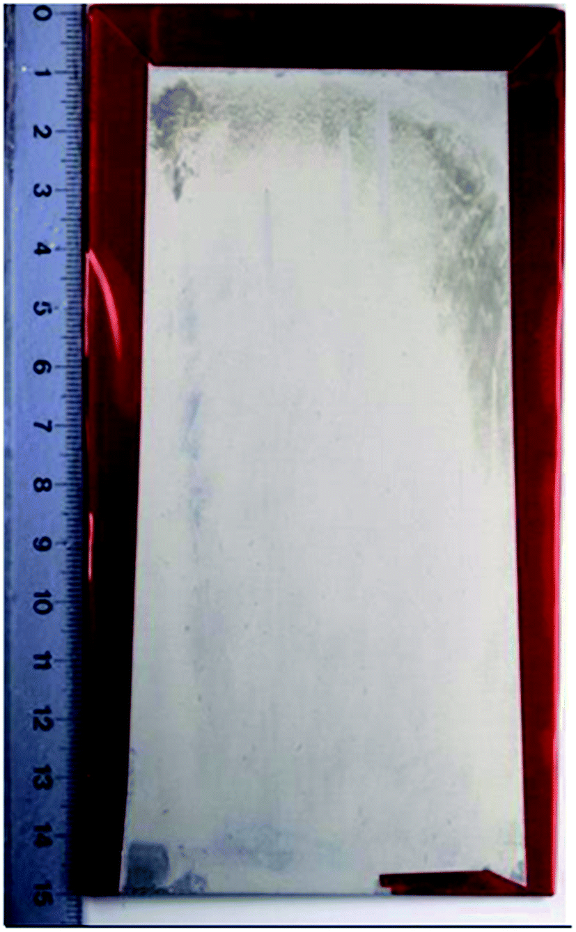 | ||
| Fig. 13 Photograph of LDH-VOx sample after 600 h exposure to SST according to ISO 9227. | ||
4. Conclusion
LDH-based sealing post-treatment for active protection of TSA anodized AA2024 is reported in the present work. During the hydrothermal treatment in Zn-containing bath the LDH structures are formed in situ on top of the anodic layer as well as in the pores sealing them. The LDH can function as “smart” nanocontainers when loaded with anionic corrosion inhibitors. The obtained results clearly demonstrate that such an active sealing can enhance the total corrosion protection performance and ensure effective healing of the artificial defects suppressing active corrosion processes.The suggested LDH-based post-treatment can be considered as a promising candidate for Cr-free sealing on the TSA anodized AA2024. However several important parameters such as temperature and treatment time still have to be optimized before transfer to the industrial environment.
Acknowledgements
This work was developed within the scope of the project CICECO-Aveiro Institute of Materials, POCI-01-0145-FEDER-007679 (FCT Ref. UID/CTM/50011/2013), financed by national funds through the FCT/MEC and when appropriate co-financed by FEDER under the PT2020 Partnership Agreement. This work was partially supported by MULTISURF (Marie Skłodowska-Curie grant agreement no. 645676) European project. SK and JT thank FCT for researcher grants (IF/00856/2013 and IF/00347/2013 respectively). Authors would like to thank Dr Andrei Salak for the performed XRD analysis.References
- C.-M. Wong and Y. Moji, Method for anodizing aluminum, US Pat., 4894127, 1989
.
- M. García-Rubio, P. Ocón, M. Curioni, G. E. Thompson, P. Skeldon, A. Lavía and I. García, Degradation of the corrosion resistance of anodic oxide films through immersion in the anodising electrolyte, Corros. Sci., 2010, 52, 2219–2227 CrossRef
- G. Boisier, N. Pébère, C. Druez, M. Villate and S. Suel, FESEM and EIS Study of Sealed AA2024 T3 Anodized in Sulfuric Acid Electrolytes: Influence of Tartaric Acid, J. Electrochem. Soc., 2008, 155, C521 CrossRef CAS
- M. Curioni, M. Saenz de Miera, P. Skeldon, G. E. Thompson and J. Ferguson, Macroscopic and Local Filming Behavior of AA2024 T3 Aluminum Alloy during Anodizing in Sulfuric Acid Electrolyte, J. Electrochem. Soc., 2008, 155, C387 CrossRef CAS
- M. Curioni, P. Skeldon, E. Koroleva, G. E. Thompson and J. Ferguson, Role of Tartaric Acid on the Anodizing and Corrosion Behavior of AA 2024 T3 Aluminum Alloy, J. Electrochem. Soc., 2009, 156(4), C147–C153 CrossRef CAS
- M. Saenz de Miera, M. Curioni, P. Skeldon and G. E. Thompson, Modelling the anodizing behaviour of aluminium alloys in sulphuric acid through alloy analogues, Corros. Sci., 2008, 50, 3410 CrossRef CAS
- Y. Li, S. Li, Y. Zhang, M. Yu and J. Liu, Enhanced protective Zn–Al layered double hydroxide film fabricated on anodized 2198 aluminum alloy, J. Alloys Compd., 2015, 630, 29–36 CrossRef CAS
- M. A. Arenas, A. Conde and J. J. de Damborenea, Effect of acid traces on hydrothermal sealing of anodising layers on 2024 aluminium alloy, Electrochim. Acta, 2010, 55, 8704–8708 CrossRef CAS
- M. García-Rubio, M. P. de Lara, P. Ocón, S. Diekhoff, M. Beneke, A. Lavía and I. García, Effect of postreatment on the corrosion behaviour of tartaric–sulphuric anodic films, Electrochim. Acta, 2009, 54, 4789–4800 CrossRef
- J. Tedim, M. L. Zheludkevich, A. N. Salak, A. Lisenkov and M. G. S. Ferreira, Nanostructured LDH-container layer with active protection functionality, J. Mater. Chem., 2011, 21, 15464–15470 RSC
- Y. Wang, D. Zhang and Z. Lu, Hydrophobic Mg–Al layered double hydroxide film on aluminum: Fabrication and microbiologically influenced corrosion resistance properties, Colloids Surf., A, 2015, 474, 44–51 CrossRef CAS
- M. Zhou, X. Pang, L. Wei and K. Gao, In situ grown superhydrophobic Zn–Al layered double hydroxides films on magnesium alloy to improve corrosion properties, Appl. Surf. Sci., 2015, 337, 172–177 CrossRef CAS
- D. Scarpellini, C. Falconi, P. Gaudio, A. Mattoccia, P. G. Medaglia, A. Orsini, R. Pizzoferrato and M. Richetta, Morphology of Zn/Al layered double hydroxide nanosheets grown onto aluminum thin films, Microelectron. Eng., 2014, 126, 129–133 CrossRef CAS
- M. Serdechnova, S. Kallip, M. G. S. Ferreira and M. L. Zheludkevich, Active Self-Healing Coating for Galvanically Coupled Multi-Material Assemblies, Electrochem. Comm, 2014, 41, 51–54 CrossRef CAS
- M. Serdechnova, A. N. Salak, F. S. Barbosa, D. E. L. Vieira, J. Tedim, M. L. Zheludkevich and M. G. S. Ferreira, Interlayer intercalation and arrangement of 2-mercaptobenzothiazolate and 1,2,3-benzotriazolate anions in layered double hydroxides: in situ X-ray diffraction study, J. Solid State Chem., 2016, 233, 158–165 CrossRef CAS
- A. I. Khan and D. O'Hare, Intercalation Chemistry of Layered Double Hydroxides: Recent Developments and Applications, J. Mater. Chem., 2002, 12, 3191–3198 RSC
- D. E. Evans and R. C. T. Slade. Structural Aspects of Layered Double Hydroxides, in Structure & Bonding, Springer-Verlag, Berlin, Germany, 2005, vol. 119, pp. 1–87 Search PubMed
- R. G. Buchheit, H. Guan, S. Mahajanam and F. Wong, Active corrosion protection and corrosion sensing in chromate-free organic coatings, Prog. Org. Coat., 2003, 47, 174–182 CrossRef CAS
- M. L. Zheludkevich, S. K. Poznyak, L. M. Rodrigues, D. Raps, T. Hack, L. F. Dick and M. G. S. Ferreira, Active protection coatings with layered double hydroxide nanocontainers of corrosion inhibitor, Corros. Sci., 2010, 52, 602–611 CrossRef CAS
- G. Williams and H. N. McMurray, Anion-exchange inhibition of filiform corrosion on organic coated AA2024-T3 aluminum alloy by hydrotalcite-like pigments, Electrochem. Solid-State Lett., 2003, 6, B9–B11 CrossRef CAS
- K. Ogle, M. Serdechnova, M. Mokaddem and P. Volovitch, The cathodic dissolution of Al, Al2Cu, and Al alloys, Electrochim. Acta, 2011, 56(4), 1711–1718 CrossRef CAS
- M. Serdechnova, P. Volovitch, F. Brisset and K. Ogle, On the cathodic dissolution of Al and Al alloys, Electrochim. Acta, 2014, 124, 9–16 CrossRef CAS
- M. L. Zheludkevich, J. Tedim and M. G. S. Ferreira, “Smart” coatings for active corrosion protection based on multi-functional micro and nanocontainers, Electrochim. Acta, 2012, 82, 314–323 CrossRef CAS
- A. Collazo, M. Hernández, X. R. Nóvoa and C. Pérez, Effect of the addition of thermally activated hydrotalcite on the protective features of sol–gel coatings applied on AA2024 aluminium alloys, Electrochimica Acta, 2011, 56(23), 7805–7814 CrossRef CAS
- T. T. X. Hang, T. A. Truc, N. T. Duong, N. Pébère and M.-G. Olivier, Layered double hydroxides as containers of inhibitors in organic coatings for corrosion protection of carbon steel, Prog. Org. Coat., 2012, 74(2), 343–348 CrossRef CAS
- T. T. X. Hang, T. A. Truc, N. T. Duong, P. G. Vu and T. Hoang, Preparation and characterization of nanocontainers of corrosion inhibitor based on layered double hydroxides, Appl. Clay Sci., 2012, 67–68, 18–25 CrossRef CAS
- V. Shkirskiy, P. Keil, H. Hintze-Bruening, F. Leroux, P. Vialat, G. Lefèvre, K. Ogle and P. Volovitch, Factors affecting MoO42− inhibitor release from Zn2Al/-based layered double hydroxide and their implication in protecting hot dip galvanized steel by means of organic coatings, ACS Appl. Mater. Interfaces, 2015, 7, 25180–25192 CAS
- M. Iannuzzi and G. S. Frankel, Mechanisms of corrosion inhibition of AA2024-T3 by vanadates, Corros. Sci., 2007, 49(5), 2371–2391 CrossRef CAS
- P. Wang, X. Dong and D. W. Schaefer, Structure and water-barrier properties of vanadate-based corrosion inhibitor films, Corros. Sci., 2010, 52(3), 943–949 CrossRef CAS
- J. Liu, Y. Zhang, M. Yu, S. Li, B. Xue and X. Yin, Influence of embedded ZnAlCe-NO3 – layered double hydroxides on the anticorrosion properties of sol–gel coatings for aluminum alloy, Prog. Org. Coat., 2015, 81, 93–100 CrossRef CAS
- J. Tedim, S. K. Poznyak, A. Kuznetsova, D. Raps, T. Hack, M. L. Zheludkevich and M. G. S. Ferreira, Enhancement of Active Corrosion Protection via Combination of Inhibitor-Loaded Nanocontainers, ACS Appl. Mater. Interfaces, 2010, 2, 1528–1535 CAS
- M. A. Habayeb and O. E. Hileman, 51V FT-NMR investigations of metavanadate ions in aqueous solutions, Can. J. Chem., 1980, 58, 2255–2261 CrossRef CAS
- C. Fares, L. Hemmouche, M. A. Belouchrani, A. Amrouche, D. Chicot and E. S. Puchi-Cabrera, Coupled effects of substrate microstructure and sulphuric acid anodizing on fatigue life of a 2017A aluminum alloy, Mater. Des., 2015, 86, 723–734 CrossRef
- G. W. Brindley and C. C. Kao, Structural and IR Relations Among Brucite-Like Divalent Metal Hydroxides, Phys. Chem. Miner., 1984, 10, 87–191 CrossRef
- J. Tedim, M. L. Zheludkevich, A. C. Bastos, A. N. Salak, A. D. Lisenkov and M. G. S. Ferreira, Influence of preparation conditions of Layered Double Hydroxide conversion films on corrosion protection, Electrochim. Acta, 2014, 117, 164–171 CrossRef CAS
- A. N. Salak, J. Tedim, A. I. Kuznetsova, L. G. Vieira, J. L. Ribeiro, M. L. Zheludkevich and M. G. S. Ferreira, Thermal Behavior of Layered Double Hydroxide Zn–Al–Pyrovanadate: Composition, Structure Transformations, and Recovering Ability, J. Phys. Chem. C, 2013, 117(8), 4152–4157 CAS
- Y. Zuo, P.-H. Zhao and J. M. Zhao, The influences of sealing methods on corrosion behavior of anodized aluminum alloys in NaCl solutions, Surf. Coat. Technol., 2003, 166(2–3), 237–242 CrossRef CAS
- K. A. Yasakau, M. L. Zheludkevich, S. V. Lamaka and M. G. S. Ferreira, Mechanism of Corrosion Inhibition of AA2024 by Rare-Earth Compounds, J. Phys. Chem. B, 2006, 110, 5515–5528 CrossRef CAS PubMed
| This journal is © The Royal Society of Chemistry 2016 |