 Open Access Article
Sonochemical/hydration–dehydration synthesis of Pt–TiO2 NPs/decorated carbon nanotubes with enhanced photocatalytic hydrogen production activity
Firas H.
Abdulrazzak
a,
Falah H.
Hussein
b,
Ayad F.
Alkaim
*cd,
Irina
Ivanova
d,
Alexei V.
Emeline
e and
Detlef W.
Bahnemann
de
aChemistry Department, College of Education for Pure Sciences, Diyala University, Diyala, Iraq
bCollege of Pharmacy, Babylon University, Hilla, Iraq
cDepartment of Chemistry, College of Science for Women, Babylon University, Hilla, Iraq
dInstitut für Technische Chemie, Leibniz Universität Hannover, Callinstrasse 3, D-30167, Hannover, Germany. E-mail: alkaim@iftc.uni-hannover.de
eLaboratory “Photoactive Nanocomposite Materials”, Saint-Petersburg State University, Ulyanovskaya str. 1, Peterhof, Saint-Petersburg 198504, Russia
First published on 20th September 2016
Abstract
Modified Pt–TiO2 NPs/decorated carbon nanotubes were synthesized utilizing sonochemical/hydration–dehydration techniques. Pt was loaded on TiO2 by a photodeposition method keeping in mind the end goal to achieve electron–hole pair separation and promote the surface reaction. The morphological and basic properties of Pt–TiO2/fCNTs were investigated by field emission scanning electron microscopy (FESEM), high resolution transmission electron microscopy (HRTEM), powder X-ray diffraction (XRD), UV–vis diffuse reflectance spectroscopy (DRS), photoluminescence (PL) and Raman spectroscopy. The selected area electron diffraction (SAED) patterns of Pt–TiO2/fCNTs were obtained utilizing TEM-based energy dispersive X-ray spectroscopy (EDXS) analysis. It was found that the TiO2 nanoparticles were uniformly distributed on the fCNTs, and the Pt particles were decorated on the surface of TiO2/fCNTs. The photocatalytic hydrogen production activity of the Pt(0.5%)–TiO2/fCNTs(0.5%) nanoparticle composites was investigated using a sacrificial agent methanol solution. Pt-loaded TiO2 demonstrated a hydrogen evolution rate around 20 times that of TiO2/fCNTs(0.5%) (fSWCNTs, fMWCNTs). When compared with platinized TiO2 in methanol, which was utilized as a control material, Pt–TiO2/fCNTs demonstrated an almost 2-fold increment in hydrogen generation.
1. Introduction
Photocatalytic water splitting for hydrogen production through semiconductor photocatalysts and light irradiation has attracted a great deal of attention as it is a promising technique to solve the energy crisis in future. Photocatalytic water splitting1 and photocatalytic reforming of biomass2,3 are two promising strategies for maintainable generation of H2. The second strategy, specifically, joins synchronous H2 generation and biomass oxidation.4–7 The major advantage is that H2 can be productively delivered by photocatalytic degradation of organic compounds present in aqueous media under mild conditions, with simultaneous treatment of industrial wastes or by-products.8 The photocatalytic process turns out to be significantly more attractive if solar energy can be utilized as the light source, being at an applicable angle particularly in countries with high insolation levels.TiO2 stands out amongst the most encouraging impetuses due to its simple accessibility, long-term stability and non-toxicity.9 Nonetheless, charge recombination as a rule prompts a low quantum productivity of TiO2. To determine this issue, numerous methodologies have been proposed to improve the photoactivity of TiO2, such as loading with noble metal10 or investigating CNTs as a coupling material with TiO2.11 In a variety of scientific fields, carbon nanotubes (CNTs) have warranted huge consideration due to their unique structural, chemical, thermal, and electrical properties12 and are used in our nanoparticle framework design.
Several recent studies have investigated the utility of coupling TiO2 to carbon materials, such as carbon nanotubes (CNTs), as an effective way to prevent the aggregation of oxide particles, leading to increased rates of photocatalytic oxidation of pollutants, or to decrease the rate of electron–hole recombination13–15 by acting as sinks for photogenerated electrons in TiO2,16,17 due to the favourable energetics of their electronic band structures, and they have been demonstrated to have a helpful impact on the photocatalytic activity of H2 production, by actuating synergies between the metal oxide and the carbon phase.8,18–20 For example, multi-walled carbon nanotubes (MWCNTs)9,21–23 and single-walled carbon nanotubes (SWCNTs)11,24 have been investigated to couple with TiO2, and the subsequent photoactivities are without a doubt moved forward.
The accessible library of nanostructured catalysts has likewise proven that the combination of three nanomaterials represents a powerful strategy to increase more profoundly the various processes taking place during photocatalysis and, eventually, to increase the efficiency of energy conversion processes.25–29 Interestingly, with simple composites, ternary hybrid composites offer the key advantage of intimate interfaces, namely facilitation of charge/energy transfer, which causes an increased lifetime of charge carriers through spatial separation of photoexcited electron–hole pairs.30
In the present work, Pt–TiO2 NPs/decorated carbon nanotube (fMWCNTs, fSWCNTs) nanocomposite materials are synthesized using a new method by a sonochemical/hydration–dehydration process, and are deliberately investigated by field emission scanning electron microscopy (FESEM), high resolution transmission electron microscopy (HRTEM), energy dispersive X-ray spectroscopy (EDXS), X-ray diffraction (XRD), UV–vis diffuse reflectance spectroscopy (DRS), photoluminescence (PL), and Raman spectroscopy. The Pt–TiO2/fCNTs (fMWCNTs, fSWCNTs) composite materials were investigated by measuring the photocatalytic production of H2 from biomass-containing aqueous solutions, namely from methanol either by Pt–TiO2/fCNTs nanocomposites, or by testing the in situ injection addition of Pt to the binary composite TiO2/fCNTs during the reaction of methanol dehydrogenation as a comparative study.
2. Experimental
2.1 Materials
The MWCNTs and SWCNTs used in this study were purchased from ALDRICH. According to the product specifications, the two compounds were fabricated by chemical vapor deposition (CVD). The SWCNTs consist of more than 90% carbon and are 77% SWCNTs, with a diameter of 0.7–1.1 nm, while the MWCNTs are 95% carbon nanotubes with a mode diameter of 4.5 nm. The metal salt precursor, namely dihydrogen hexachloro palatinate (IV) hexahydrate (H2PtCl6·6H2O), was supplied by Alfa Aesar. Nitric acid (65 wt% HNO3) and sulfuric acid (37 wt% H2SO4) were obtained from Fluka and Sigma-Aldrich, respectively.2.2. Functionalization of carbon nanotubes
0.2 g of CNTs (MWCNTs, SWCNTs) was placed in a 500 mL conical flask equipped with a condenser, and 150 mL of HNO3![[thin space (1/6-em)]](https://www.rsc.org/images/entities/char_2009.gif) :
:![[thin space (1/6-em)]](https://www.rsc.org/images/entities/char_2009.gif) H2SO4 (1
H2SO4 (1![[thin space (1/6-em)]](https://www.rsc.org/images/entities/char_2009.gif) :
:![[thin space (1/6-em)]](https://www.rsc.org/images/entities/char_2009.gif) 2) with a concentration of 10 mol L−1 was added. The mixture was activated under magnetic stirring and sonicated for 2 h at 30 °C, and then this solution was heated to 70 °C for 8 h without stirring. Then the recovered CNTs were washed several times with distilled water up to neutral pH, and then dried at 383 K overnight. This oxidative treatment is very important to help remove amorphous carbon and metallic impurities from the as-produced CNTs,31 and furthermore to increase the atomic oxygen concentration and the distribution of hydroxyl, carbonyl and carboxylic acid groups.32
2) with a concentration of 10 mol L−1 was added. The mixture was activated under magnetic stirring and sonicated for 2 h at 30 °C, and then this solution was heated to 70 °C for 8 h without stirring. Then the recovered CNTs were washed several times with distilled water up to neutral pH, and then dried at 383 K overnight. This oxidative treatment is very important to help remove amorphous carbon and metallic impurities from the as-produced CNTs,31 and furthermore to increase the atomic oxygen concentration and the distribution of hydroxyl, carbonyl and carboxylic acid groups.32
2.3. Preparation of Pt–TiO2/fCNTs composites
The TiO2 used to prepare the Pt–TiO2/fCNTs composites has been produced in our laboratory through a hydrothermal method.10Pt/TiO2 was prepared by the photodeposition method as follows: 1 g of TiO2 nanoparticles photocatalyst was suspended by stirring in 100 mL aqueous solution containing the desired concentration of H2PtCl6 to obtain a 0.5 wt% Pt-loaded TiO2 photocatalyst. The resulting solution was irradiated with UV(A) light employing a Philips Fluorescence Hg lamp (illumination intensity: 1.0 mW cm−2) for 2 h under an Ar atmosphere. Afterwards, 1 mL methanol was injected into the solution followed by further illumination for 10 h. The obtained powder was separated by centrifugation, washed with water, and dried at 100 °C for 12 h.33 The composites of Pt–TiO2/fCNTs were prepared firstly by sonicating the solution followed by simple evaporation and drying (hydration/dehydration method) adapted from procedures described in the literature.16,34 First, approximately 50 mg fCNTs was dispersed in water in a 100 mL beaker and sonicated for 60 min, and the fCNTs content was fixed at 0.5 wt%. Pt/TiO2 nanoparticles were added to the suspension while stirring, and the suspension containing fCNTs (fSWCNTs, fMWCNTs) and Pt/TiO2 nanoparticles was heated to 80 °C until complete evaporation of water, and the resulting composites were dried overnight in an oven at 100 °C to avoid any physicochemical change of the fCNTs (fSWCNTs, fMWCNTs) that occurs at higher temperatures in the presence of oxygen.
2.4 Photocatalytic activity for H2 production
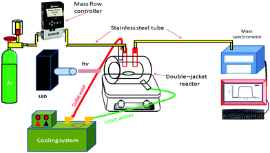
The photocatalytic hydrogen production runs were carried out in an experimental setup comprising of a gas supply, a mass flow controller, and a 100 cm3 double-jacket quartz glass photoreactor connected to a quadrupole mass spectrometer (QMS) for gas analysis (Hiden HPR-20) as schematically shown in Fig. 1.35 The system is continuously purged with Ar as the carrier gas, whereby the Ar flow is controlled by a mass flow controller (MFC). In a standard run, 0.05 g of Pt(0.5%)/TiO2, TiO2/fSWCNTs(0.5%), TiO2/fMWCNTs(0.5%), Pt(0.5%)–TiO2/fSWNTs(0.5%) and Pt(0.5%)–TiO2/fMWCNTs(0.5%) was suspended in 60 mL of an aqueous methanol solution (5 mM) by sonication. The suspension was transferred into the photoreactor and purged with Ar for 30 min to evacuate disintegrated O2. After that, the reactor was connected to the mass flow controller and to the Q/C capillary sampling inlet of the QMS through metal flanges and adapters. To remove the air in the headspace of the reactor, an Ar gas stream was consistently flown through the reactor before irradiation, until no traces of molecular oxygen or nitrogen could be distinguished by the QMS. The Ar gas flow rate through the reactor was kept constant at 10 cm3 min−1 during the photocatalytic tests. The inlet flow rate/gas consumption by the QMS is 1 cm3 min−1 and the excess gas is directed towards the exhaust. The sampling rate of the QMS is in the millisecond time range, thus allowing fast tracking of the reaction. After stabilization of the system background, the reactor was irradiated from the outside utilizing collimated UV light of a strong 365 nm LED (Thorlabs/USA). For quantitative analysis of H2, the QMS was calibrated employing standard diluted H2, in Ar (Linde Gas, Germany).2.5. Analytical instruments
The morphological analysis of TiO2, TiO2/fSWCNTs(0.5%), TiO2/fMWCNTs(0.5%), Pt(0.5%)/TiO2, Pt(0.5%)–TiO2/fSWCNTs(0.5%), and Pt(0.5%)–TiO2/fMWCNTs(0.5%) was done using different techniques.Powder X-ray diffraction (XRD) was performed in a Bruker AXS D4 Endeavour diffractometer using a reflection geometry with fixed divergence slits, Cu Kα1,2 radiation, and a nickel filter. Three thousand data points were collected with a step width of 0.02° per step in the 2θ range from 20 to 80°. To determine the particle size, and element type, field emission scanning electron microscopy (FESEM) measurements were carried out on a JEOL JSM-6700F field emission instrument using a secondary electron detector (SE) at an accelerating voltage of 2 kV, and HRTEM and energy dispersive X-ray spectroscopy (EDXS) were performed at 200 kV with an ultrahigh resolution pole piece (CS = 0.5 mm), which provides a point resolution better than 0.19 nm. Raman spectra of the samples were recorded in the 45–2300 cm−1 spectral region at ambient temperature using a SENTERRA Raman spectrometer (Bruker) with a resolution of 1 cm−1 (the excitation laser wavelength was 532 nm. Data were collected using an 1800 grating in the Raman shift range from 0 to 2300 cm−1, and the laser beam power was 20 mW).
Photoluminescence (PL) spectroscopy of the synthesized composites was done at room temperature on a Hitachi F2500 spectrofluorometer using a Xe lamp with an excitation wavelength of 355 nm.
The bandgap energy of the catalysts was measured using diffuse reflectance spectroscopy (DRS). The reflectance spectra of the samples within the 200–700 nm wavelength range were recorded with a UV–vis spectrophotometer (Varian Cary 100) equipped with a Labsphere integrating sphere diffuse reflectance accessory and using BaSO4 as the reference material. UV–vis spectra were performed in the diffuse reflectance mode (R) and transformed to the Kubelka–Munk function F(R) to separate the extent of light absorption from scattering. Furthermore the bandgap values were obtained from the plot of the modified Kubelka–Munk function (F(R)E)1/2) versus the energy of the absorbed light E:36
The Brunauer–Emmett–Teller (BET) surface area of the prepared nanocomposites was analysed by nitrogen adsorption using a Micromeritics ASAP 2020 nitrogen adsorption apparatus (USA). All measurements for the surface area were repeated three times and the average of these measurements was calculated.
3. Results and discussion
3.1 Catalyst characterization
XRD was used to characterize the difference of phase structures and average crystallite sizes of the samples Fig. 2 shows comparison of XRD patterns of fCNTs (fSWCNTs, fMWCNTs), TiO2/fCNTs(0.5%) (fSWCNTs, fMWCNTs), Pt/TiO2, and Pt(0.5%)/TiO2/fCNTs(0.5%) (fSWCNTs, fMWCNTs) composites. Also, Fig. 2 shows XRD patterns of Pt–TiO2/fCNTs composite that has diffraction peaks of TiO2 and Pt/TiO2. The peak at 2θ value of 25 is broad indicating (0 0 2) phase of fCNTs and (1 0 1) phase of TiO2 have overlapped. Otherwise, no apparent peaks for fCNTs or Pt are observed because of its lower loading content and weak crystallization37 However, the existence of fCNTs can be clearly identified by Raman analysis as discussed later.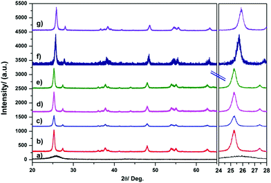 | ||
| Fig. 2 X-ray diffraction of (a) pure TiO2, (b) pure CNTs (fMWCNTs), (c) Pt/TiO2, (d) TiO2/fMWCNTs, (e) TiO2/fSWCNTs, (f) Pt–TiO2/fSWCNTs, and (g) Pt–TiO2/fMWCNTs. | ||
There are diffraction peaks corresponding to fCNTs; the two peaks at 26.5° and 43.5° can be attributed to reflection from C(0 0 2) and C(1 0 0) facets.38,39 The phases of the synthesized TiO2 anatase structure are well known. These features are observed in the XRD spectra for the Pt–TiO2 and Pt–TiO2/fCNTs (fSWCNTs, fMWCNTs) nanoparticle composites. In addition, the peaks corresponding to the Pt component have not been observed; moreover as shown in Fig. 2, the peaks related to fCNTs are absent from the XRD patterns caused by the overlap of the (0 0 2) peak of fCNTs and (1 0 1) phase of TiO2 as well, because of the amorphous structure of the impregnated fibers and because of the fact that the intense graphite peaks (0 0 2) overlap with the TiO2 anatase (0 0 1) reflections, which thus obscure the graphite peaks because the amount of TiO2 that is present in the material is much larger than the amount of fCNTs.40 The crystal sizes of all samples also can be estimated using the Scherrer equation. Taking the peak of the (101) planes into account, the average crystalline sizes of the samples are illustrated in Table 1.
| Material label | Surface area/m2 g−1 | Crystal size/nm | Bandgap/eV |
|---|---|---|---|
| fMWCNTs | 286.4 | 7.64 | — |
| fSWCNTs | 570.2 | 6.52 | — |
| TiO2 | 113.1 | 11.44 | 3.11 |
| Pt/fMWCNTs | 92.77 | 9.71 | — |
| Pt/fSWCNTs | 105.34 | 8.42 | — |
| Pt/TiO2 | 107.41 | 12.72 | 2.85 |
| Pt–TiO2/fMWCNTs | 111.45 | 13.61 | 2.73 |
| Pt–TiO2/fSWCNTs | 118.23 | 14.32 | 2.61 |
The nano-surface structures of the Pt–TiO2/fCNTs (MWCNTs) nanoparticle composites were characterized by FESEM and HRTEM-based EDXS analysis. As shown in Fig. 3(a) and (b) with images of different magnifications, fCNTs (fMWCNTs) were coated with well-dispersed Pt/TiO2 nanoparticles, and their distribution was uniform. The dispersion of small particles is optimal for surface catalysis as this can provide more reactive sites for the reactants than aggregated particles.29 HRTEM was used to further examine the surface structure of the Pt–TiO2/fMWCNTs nanoparticle composites as shown in Fig. 3(c) and (d). The images confirm that the surface of the fCNTs has been uniformly decorated with Pt/TiO2 particles of size ∼10–20 nm. Also, the Pt–TiO2/fCNTs nanoparticle composites were found to be covered with aciniform structures of Pt–TiO2, as shown in Fig. 3(c) and (d).
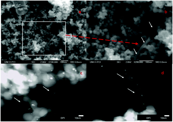 | ||
| Fig. 3 FESEM images of Pt(0.5%)/TiO2–fMWCNTs(0.5%) (a and b); HRTEM images of Pt(0.5%)–TiO2/fMWCNTs(0.5%) (c and d). | ||
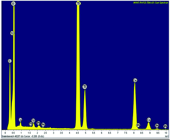
The HRTEM images (Fig. 3(c) and (d)) of Pt–TiO2/fMWCNTs show that some of the Pt/TiO2 nanoparticles deposit on the fMWCNTs, and it is clear when Fig. 3(c) is magnified as shown in Fig. 3(d), because its surface contains an abundance of oxygen-containing groups, which is beneficial for preferential heterogeneous nucleation and growth of nanoparticles. The chemical composition of the sample Pt–TiO2/fMWCNTs was determined by energy dispersive X-ray spectroscopy (EDXS). The EDXS spectrum (Fig. 4) confirms that the sample consists of C, O, Ti and Pt elements, as expected.
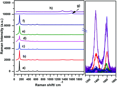
Fig. 5 summarizes the Raman spectra of the Pt–TiO2/fCNTs (fMWCNTs, fSWCNTs) composites. The characteristic Raman modes of the anatase TiO2 phase were readily detected at 150 cm−1 (Eg), 395.1 cm−1 (B1g), 512.5 cm−1 (A1g + B1g), and 636.7 cm−1 (Eg) due to anatase as well as the very low intensity 235 cm−1 (A1g) band ascribed to rutile.25,41 As for the fCNTs (fSWCNTs, fMWCNTs), two typical Raman bands are observed (Fig. 5(g) and (h)); one at 1582 cm−1, which is indicative of the G band (Raman-allowed E2g mode) characterizing the crystalline nature of the fCNTs, together with a band at 1332 cm−1 (D band, assigned to the A1g phonon mode) originating from the disordered sp2 carbon42,43
On the other hand, TiO2 causes an increase in the atomic disorder in the TiO2/fCNTs system through the creation of defects, as depicted in the inset of Fig. 5. This effect could be attributed to the ultrasonic treatment during the synthesis and the interaction between acid-treated fCNTs and TiO2 or by the effect of TiO2/fCNTs platinized by the photodeposition process.44
No significant change in the position and widths of these bands is noted. Instead, the D/G intensity ratio undergoes a slight increase with respect to the value measured in TiO2/fCNTs or Pt(0.5%)–TiO2/fCNTs(0.5%) as is clear in Fig. 5, while the relative intensity of the Raman TiO2 modes changes with varying the CNTs or Pt loading.
As previously pointed out,45,46 Raman analysis demonstrates that the addition of TiO2 or Pt/TiO2 to the fCNTs leads to an enhancement of the D/G integrated intensity ratio, i.e. of the structural disorder of the graphitic network. Comparing the spectra of TiO2/fCNTs and Pt(0.5%)–TiO2/fCNTs(0.5%) (Fig. 5(d)–(f)), a further slight increase can be noted in all the samples, caused by the anchoring of the TiO2 NPs on oxygenated groups introduced during fCNTs surface functionalization.47
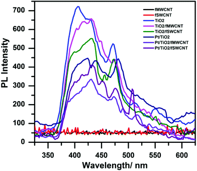
Photoluminescence is a powerful tool to probe the electron–hole pair formation and their recombination at surfaces.48,49 The PL measurements were carried out with pure TiO2, Pt/TiO2 and with loading and unloading Pt on the TiO2/fCNTs (fSWCNTs, fMWCNTs) composites, as shown in Fig. 6. A maximum peak around 400 nm is observed, which is due to the bandgap transition of TiO2. The small peaks in the wavelength region of 450–475 nm are assigned to excitonic PL resulting from surface defects/vacancies.49 The PL spectra can be attributed to the recombination process of the electron–hole pair at the surface.50 An overall reduction in PL intensity was observed with either fCNTs (fMWCNTs, fSWCNTs) or Pt photodeposited on the TiO2 surface. Furthermore a higher reduction was detected in the presence of both fCNTs (fSWCNTs, fSWCNTs) and Pt on the TiO2 surface as shown in Fig. 6. Therefore, Pt–TiO2/fCNTs has a lower recombination rate of electron–hole pairs compared with that of Pt/TiO2 or TiO2/fCNTs.
The decrease in PL intensity for the composite Pt–TiO2/fCNTs indicates transfer of photogenerated electrons from TiO2 to fCNTs and Pt, thus reducing the recombination probability and lowering the PL intensity.51 This may be one reason why the Pt–TiO2/fCNTs showed a higher photoactivity of hydrogen evolution than Pt/TiO2 or TiO2/fCNTs (fMWCNTs, fSWCNTs) did.52 Also the reduction is greater in the fSWCNTs composites than in the fMWCNTs composite, which is consistent with the evidence of better attachment for the Pt–TiO2/fSWCNTs composite than for the Pt–TiO2/fMWCNTs composite. As expected, no luminescence was observed in the range of 400–650 nm for the fCNTs (fSWCNTs, fMWCNTs).16
In order to elucidate the optical response and to determine the bandgaps of the nanocomposite samples, UV–visible diffuse reflectance spectroscopy (UV–vis DRS) was carried out. The bandgap energy (Eg) of these samples was estimated from the plot of the square root of the Kubelka–Munk function versus photon energy as shown in Fig. 7. The characteristic spectrum of the fundamental absorption edge at 370 nm (with a 3.1 eV band edge) was clearly observed. The Pt–TiO2/fCNTs nanocomposite displayed stronger absorption than TiO2/CNTs did, and the band edge of Pt–TiO2/fCNTs is 2.73 and 2.61 eV respectively, and the results are illustrated in Table 1. It is suggested that the surface electric charge of the nanocomposite increases due to the fCNTs introduction, which may lead to modifications of the procedure of electron–hole pair formation during visible light irradiation.53 Also the Pt–TiO2/fCNTs photocatalysts probably exhibit surface plasmon resonance (SPR) due to the presence of Pt particles,54 or ascribed to low-energy transitions between the valence band of TiO2 and localized energy levels introduced to the bandgap by deposited metal clusters.33
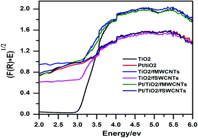 | ||
| Fig. 7 Plot of transferred Kubelka–Munk function versus energy of the light absorbed of the prepared nanocomposites. | ||
The surface area for pristine and modified TiO2 was measured using the Brunauer–Emmett–Teller method and the results are listed in Table 1. The results show that the Pt–TiO2/fCNTs framework has a larger specific surface area than that of Pt/fCNTs. Since there is more surface area with TiO2, it is expected that Pt shows a superior dispersion on the TiO2/fCNTs support, leaving more area exposed for the surface reaction to take place.44
3.2. Photocatalytic hydrogen production
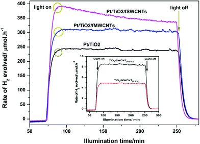
The activities of the composites with 0.5% fCNTs (fSWCNTs, fMWCNTs) loading on Pt/TiO2 were tested in the photocatalytic evolution of hydrogen from aqueous methanol solutions. Blank experiments showed no appreciable H2 evolution in the absence of either irradiation light or photocatalysts of Pt–TiO2/fCNTs, and also no activity was observed over pure fCNTs or TiO2 in the presence of light, which may be attributed to the presence of overpotential in the production of H2 on the TiO2 surface and the fast backward recombination of hydrogen and oxygen into water, making TiO2 less active in photocatalytic water splitting due to the high recombination between CB electrons and VB holes in pure TiO2.Fig. 8 displays the photocatalytic activities for H2 evolution over Pt/TiO2, TiO2/fSWCNTs, TiO2/fMWCNTs, Pt–TiO2/fSWCNTs, and Pt–TiO2/fMWCNTs. All the samples were irradiated for 3 hours. It can be seen clearly from Fig. 8 that Pt(0.5%)–TiO2/fCNTs(0.5%) exhibits a significant enhancement in H2 evolution as compared to TiO2/fCNTs (fSWCNTs, fMWCNTs) and even Pt/TiO2.
Thus an increase in the photocatalytic performance of Pt–TiO2/fCNTs is mainly due to photodeposition of Pt nanoparticles. It is well known that the deposition of noble metals usually enhances the separation and prolongs the lifetime of photogenerated electrons and holes (e−–h+), resulting in the improved photocatalytic activity.55 This leads to an increase of photocatalytic hydrogen generation, which is attributed to atomic Pt and results in an increase of electron sinks, thus improving the photocatalyst activity with moderate reaction rates.56
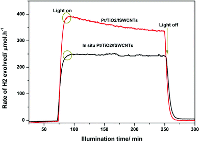
Comparative experiments were used to understand the effect of the position of Pt on the reaction by (in situ) injection of Pt into TiO2/fCNTs photocatalysts with the same composition ratio as that prepared in the photodeposition method. Fig. 9 shows that in situ injection of Pt ions to TiO2/fSWCNTs achieved a rate of 254 μmol h−1, which is higher than that for TiO2/fCNTs (fSWCNTs, fMWCNTs), but lower than that for Pt–TiO2/fSWCNTs (355 μmol h−1). This demonstrates that the strong interaction between fCNTs and Pt/TiO2 formed in the sonochemical/hydration–dehydration and photodeposition reaction plays a crucial role in the water reduction process.
All of that confirms two facts, the first being that the addition of fCNTs and Pt simultaneously has an effect that is greater than that from the addition of each of them individually. The second fact is that the synergic roles depend on the nature of distribution and concoctions between Pt with TiO2 and fCNTs with TiO2 to form Pt–TiO2/fCNTs.
3.3. Mechanism for the enhancement of the photocatalytic activity by Pt–TiO2/fCNTs
It is well known that the light absorption capability of the photocatalyst and separation of photogenerated e−/h+ pairs are crucial factors influencing the photoactivity, as well as the formation of a semiconductor–metal junction (Schottky barrier) where there is a space charge separation region. This Schottky barrier will result in the metal possessing an excess negative charge and the semiconductor an excess positive charge.57 Thus, after TiO2 absorbs a photon, the excited electron and hole need to be separated and transferred to the surface of TiO2, to react with corresponding water or sacrificial agents.58 The excited e− may migrate into either the metal surface or to the nano-cylinder of fCNTs causing a reduction in the chance of recombination of e−/h+. Meanwhile upon light irradiation, the photogenerated electrons are excited from the valence band (VB) to the conduction band (CB) leaving positive holes in the VB. The holes accumulated at the valence band oxidize methanol to give a methoxide ion (radical species) and a proton.The excited electrons migrate to the Pt nanoparticles which act as electron traps then reduce the protons to produce H2. The general functions of Pt and fCNTs can be represented in two probabilities: the first is related to the Pt nanoparticles that are photodeposited on TiO2 forming a Schottky barrier at the Pt–TiO2 interface based on the difference between the Pt work-function (5.7 eV)59 and the electron affinity (χ = 3.8 eV) of the TiO2 conduction band. The second probability may be due to the excited electrons transferred from the low electron conductivity of the TiO2 phase to the high electron conductivity of the carbon phase in the TiO2/CNTs composites.60 Besides, well mixed TiO2 particles with the fCNTs network create local potential differences in the TiO2 phase which spread through the sample, resulting in more effective e−/h+ separation within the entire sample.61 The work-functions of fCNTs (fSWCNTs, fMWCNTs) are about 4.8 and 4.3 eV respectively62 when fCNTs were added, and charge transfer from the TiO2 conduction band (ECB = 0.5 V versus normal hydrogen electrode (NHE)) to the SWCNTs conduction band (ECB = 0.3 V versus NHE) is therefore energetically favourable for all types of CNTs.63
In both cases of the suggested mechanism, the injected electrons will assist as H2 evolution sites to reduce water molecules. Meanwhile, methanol (donor) is oxidized by donating the electrons to Pt or fCNTs. As shown in Fig. 9, the fSWCNTs have higher activities compared to those of fMWCNTs, and the same results have been found in previously published work.63 The SWCNTs are more favourable for charge transfer64 as compared to the MWCNTs, which may be due to them acting as mid-gap bands, causing the possible multi-electron–hole pair (exciton) generation by absorption of single high energy photons in the UV region across these multiple low energy bandgaps.65 Meanwhile for MWCNTs, the origin of the photoconductivity is less clear.66 Yao et al.16 reported that the TiO2/fSWCNTs composite demonstrated a higher photocatalytic activity than that of the TiO2/fMWCNTs composite under UV light irradiation. This occurrence is believed to be related to the higher degree of interphase contact that can be achieved at the TiO2 surface with the bundles of small individual SWCNTs.67 Woan et al. reported that a hydrothermally synthesized SWCNT–TiO2 hybrid showed superior enhancement in the photocatalytic degradation of pirimicarb compared with that of MWCNTs/TiO2,19 which is attributed to the higher separation efficiency of photogenerated carriers that was achieved because of the high conductivity of SWCNTs.68 All of these explanations and reasons lead to the ternary mechanism in Fig. 10, which produces H2 gas in three routes, with the probabilities for Pt in two lines while there is one line for fCNTs. The practical proof of these results was accrued when an in situ experiment was done which mostly localized the Pt on the surfaces of fCNTs, and showed the percent of Pt that was localized on the surface of TiO2.
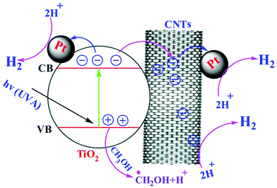 | ||
| Fig. 10 Schematic diagram for the mechanism of the reactions for the ternary composite (Pt–TiO2/fCNTs). | ||
4. Conclusions
In summary, a Pt(0.5%)–TiO2/fCNTs(0.5%) ternary hybrid has been successfully synthesized by a new sonochemical/hydration–dehydration route. The results show that Pt/TiO2 was more active than the binary composites TiO2/fCNTs. Among the various nanostructures (Pt–TiO2/fSWCNTs, Pt–TiO2/fMWCNTs, Pt/TiO2, and TiO2/fCNTs), Pt–TiO2/fSWCNTs shows the maximum photocatalytic H2 production rate (355 μmol h−1) due to having the best charge carrier transfer and separation, caused by a reduction in the recombination rate of electron–hole pairs compared with the other nanocomposites. Furthermore, the results show that the photocatalytic activity of the ternary hybrid catalysts is highly dependent on the type of fCNTs, as investigated in our work, with the activity of fSWCNTs being higher than that of fMWCNTs for hydrogen production. Finally the indicator for this behavior was the in situ injection of Pt to the binary composite TiO2/fSWCNTs(0.5%), which shows a reduction in activity as compared with Pt(0.5%)/TiO2 and Pt–TiO2/SWNTs. Furthermore, photocatalyst-based flexible fCNTs have advantages for industrial application because of the type-dependence of fCNTs which gives a cost-effective co-catalyst for photocatalytic H2 production.Acknowledgements
Detlef W. Bahnemann and I. Ivanova acknowledge financial support from the BMBF (Bundesministerium für Bildung und Forschung), research project DuaSol (03SF0482C). The present study was performed within the Project “Establishment of the Laboratory Photoactive Nanocomposite Materials” no. 14.Z50.31.0016 supported by a mega-grant of the Government of the Russian Federation.References
- H. Bahruji, M. Bowker, P. R. Davies, L. S. Al-Mazroai, A. Dickinson, J. Greaves, D. James, L. Millard and F. Pedrono, Sustainable H2 gas production by photocatalysis, J. Photochem. Photobiol., A, 2010, 216, 115–118 CrossRef CAS.
- D. I. Kondarides, V. M. Daskalaki, A. Patsoura and X. E. Verykios, Hydrogen Production by Photo-Induced Reforming of Biomass Components and Derivatives at Ambient Conditions, Catal. Lett., 2008, 122, 26–32 CrossRef CAS.
- A. Speltini, M. Sturini, F. Maraschi, D. Dondi, G. Fisogni, E. Annovazzi, A. Profumo and A. Buttafava, Evaluation of UV-A and solar light photocatalytic hydrogen gas evolution from olive mill wastewater, Int. J. Hydrogen Energy, 2015, 40, 4303–4310 CrossRef CAS.
- M. Ilie, B. Cojocaru, V. I. Parvulescu and H. Garcia, Improving TiO2 activity in photo-production of hydrogen from sugar industry wastewaters, Int. J. Hydrogen Energy, 2011, 36, 15509–15518 CrossRef CAS.
- A. Speltini, M. Sturini, F. Maraschi, D. Dondi, A. Serra, A. Profumo, A. Buttafava and A. Albini, Swine sewage as sacrificial biomass for photocatalytic hydrogen gas production: Explorative study, Int. J. Hydrogen Energy, 2014, 39, 11433–11440 CrossRef CAS.
- A. Speltini, M. Sturini, D. Dondi, E. Annovazzi, F. Maraschi, V. Caratto, A. Profumo and A. Buttafava, Sunlight-promoted photocatalytic hydrogen gas evolution from water-suspended cellulose: a systematic study, Photochem. Photobiol. Sci., 2014, 13, 1410–1419 CAS.
- N. M. Gupta, S. Kelkar and P. Korake, The quenching effect of uranyl species in the photoluminescence emission and visible-light-driven water dissociation activity of CdS and TiO2 photocatalysts, Photochem. Photobiol. Sci., 2016, 15, 758–766 CAS.
- C. G. Silva, M. J. Sampaio, R. R. Marques, L. A. Ferreira, P. B. Tavares, A. M. Silva and J. L. Faria, Photocatalytic production of hydrogen from methanol and saccharides using carbon nanotube-TiO2 catalysts, Appl. Catal., B, 2015, 178, 82–90 CrossRef CAS.
- Q. Zeng, H. Li, H. Duan, Y. Guo, X. Liu, Y. Zhang and H. Liu, A green method to prepare TiO2/MWCNT nanocomposites with high photocatalytic activity and insights into the effect of heat treatment on photocatalytic activity, RSC Adv., 2015, 5, 13430–13436 RSC.
- A. F. Alkaim, T. A. Kandiel, F. H. Hussein, R. Dillert and D. W. Bahnemann, Solvent-free hydrothermal synthesis of anatase TiO2 nanoparticles with enhanced photocatalytic hydrogen production activity, Appl. Catal., A, 2013, 466, 32–37 CrossRef CAS.
- C. Bo, P. Tianyou, Z. Xiaohu, M. Jing, L. Kan and Z. Xungao, Synthesis of C60-decorated SWCNTs (C60-d-CNTs) and its TiO2-based nanocomposite with enhanced photocatalytic activity for hydrogen production, Dalton Trans., 2013, 42, 3402–3409 RSC.
- R. H. Baughman, A. A. Zakhidov and W. A. de Heer, Carbon Nanotubes–the Route Toward Applications, Science, 2002, 297, 787–792 CrossRef CAS PubMed.
- G. An, W. Ma, Z. Sun, Z. Liu, B. Han, S. Miao, Z. Miao and K. Ding, Preparation of titania/carbon nanotube composites using supercritical ethanol and their photocatalytic activity for phenol degradation under visible light irradiation, Carbon, 2007, 45, 1795–1801 CrossRef CAS.
- W. Wang, P. Serp, P. Kalck and J. L. Faria, Visible light photodegradation of phenol on MWNT-TiO2 composite catalysts prepared by a modified sol-gel method, J. Mol. Catal. A: Chem., 2005, 235, 194–199 CrossRef CAS.
- G. Zhu, H. Wang, G. Yang, L. Chen, P. Guo and L. Zhang, A facile synthesis of ZnO/CNT hierarchical microsphere composites with enhanced photocatalytic degradation of methylene blue, RSC Adv., 2015, 5, 72476–72481 RSC.
- Y. Yao, G. Li, S. Ciston, R. M. Lueptow and K. A. Gray, Photoreactive TiO2/Carbon Nanotube Composites: Synthesis and Reactivity, Environ. Sci. Technol., 2008, 42, 4952–4957 CrossRef CAS PubMed.
- B. Ahmmad, Y. Kusumoto, S. Somekawa and M. Ikeda, Carbon nanotubes synergistically enhance photocatalytic activity of TiO2, Catal. Commun., 2008, 9, 1410–1413 CrossRef CAS.
- R. Leary and A. Westwood, Carbonaceous nanomaterials for the enhancement of TiO2 photocatalysis, Carbon, 2011, 49, 741–772 CrossRef CAS.
- K. Woan, G. Pyrgiotakis and W. Sigmund, Photocatalytic Carbon-Nanotube–TiO2 Composites, Adv. Mater., 2009, 21, 2233–2239 CrossRef CAS.
- C. G. Silva and J. L. Faria, Photocatalytic oxidation of benzene derivatives in aqueous suspensions: Synergic effect induced by the introduction of carbon nanotubes in a TiO2 matrix, Appl. Catal., B, 2010, 101, 81–89 CrossRef CAS.
- S. Da Dalt, A. K. Alves, F. A. Berutti and C. P. Bergmann, Designing of TiO2/MWCNT Nanocomposites for Photocatalytic Degradation of Organic Dye, Part. Sci. Technol., 2015, 33, 308–313 CrossRef CAS.
- B. Reti, K. Mogyorosi, A. Dombi and K. Hernadi, Substrate dependent photocatalytic performance of TiO2/MWCNT photocatalysts, Appl. Catal., A, 2014, 469, 153–158 CrossRef CAS.
- S. Muduli, W. Lee, V. Dhas, S. Mujawar, M. Dubey, K. Vijayamohanan, S.-H. Han and S. Ogale, Enhanced Conversion Efficiency in Dye-Sensitized Solar Cells Based on Hydrothermally Synthesized TiO2-MWCNT Nanocomposites, ACS Appl. Mater. Interfaces, 2009, 1, 2030–2035 CAS.
- K. Vajda, K. Mogyorosi, Z. Nemeth, K. Hernadi, L. Forro, A. Magrez and A. Dombi, Photocatalytic activity of TiO2/SWCNT and TiO2/MWCNT nanocomposites with different carbon nanotube content, Phys. Status Solidi B, 2011, 248, 2496–2499 CrossRef CAS.
- M. Mokhtar Mohamed, G. Osman and K. S. Khairou, Fabrication of Ag nanoparticles modified TiO2/CNT heterostructures for enhanced visible light photocatalytic degradation of organic pollutants and bacteria, J. Environ. Chem. Eng., 2015, 3, 1847–1859 CrossRef CAS.
- X. Wang, J. Zhang and H. Zhu, Pt-Au/CNT@TiO2 as a High-Performance Anode Catalyst for Direct Methanol Fuel Cells, Chin. J. Catal., 2011, 32, 74–79 CrossRef CAS.
- M. N. Uddin, M. S. Islam, M. R. Mazumder, M. A. Hossain, M. Elias, I. A. Siddiquey, M. H. Susan, D. K. Saha, M. M. Rahman, A. M. Asiri and S. Hayami, Photocatalytic and antibacterial activity of B/N/Ag co-doped CNT–TiO2 composite films, J. Inclusion Phenom. Macrocyclic Chem., 2015, 82, 229–234 CrossRef CAS.
- M. Sangari, M. Umadevi, J. Mayandi and J. P. Pinheiro, Photocatalytic degradation and antimicrobial applications of F-doped MWCNTs/TiO2 composites, Spectrochim. Acta, A, 2015, 139, 290–295 CrossRef CAS PubMed.
- Y. Koo, G. Littlejohn, B. Collins, Y. Yun, V. N. Shanov, M. Schulz, D. Pai and J. Sankar, Synthesis and Characterization of Ag-TiO2-CNT Nanoparticle Composites with High Photocatalytic Activity under Artificial Light, Composites, Part B, 2014, 57, 105–111 CrossRef CAS.
- A. Moya, A. Cherevan, S. Marchesan, P. Gebhardt, M. Prato, D. Eder and J. J. Vilatela, Oxygen vacancies and interfaces enhancing photocatalytic hydrogen production in mesoporous CNT/TiO2 hybrids, Appl. Catal., B, 2015, 179, 574–582 CrossRef CAS.
- C. Bergeret, J. Cousseau, V. Fernandez, J.-Y. Mevellec and S. Lefrant, Spectroscopic evidence of carbon nanotubes’ metallic character loss induced by covalent functionalization via nitric acid purification., J. Phys. Chem. C, 2008, 112, 16411–16416 CAS.
- K. A. Wepasnick, B. A. Smith, K. E. Schrote, H. K. Wilson, S. R. Diegelmann and D. H. Fairbrother, Surface and structural characterization of multi-walled carbon nanotubes following different oxidative treatments, Carbon, 2011, 49, 24–36 CrossRef CAS.
- A. F. Alkaim, R. Dillert and D. W. Bahnemann, Effect of polar and movable (OH or NH2 groups) on the photocatalytic H2 production of alkyl-alkanolamine: a comparative study, Environ. Technol., 2015, 36, 2190–2197 CrossRef CAS PubMed.
- S. M. Miranda, G. E. Romanos, V. Likodimos, R. R. N. Marques, E. P. Favvas, F. K. Katsaros, K. L. Stefanopoulos, V. J. P. Vilar, J. L. Faria, P. Falaras and A. N. M. T. Silva, Pore structure, interface properties and photocatalytic efficiency of hydration/dehydration derived TiO2/CNT composites, Appl. Catal., B, 2014, 147, 65–81 CrossRef CAS.
- T. A. Kandiel, I. Ivanova and D. W. Bahnemann, Long-term investigation of the photocatalytic hydrogen production on platinized TiO2: an isotopic study, Energy Environ. Sci., 2014, 7, 1420–1425 CAS.
- A. A. Ismail, D. W. Bahnemann, I. Bannat and M. Wark, Gold Nanoparticles on Mesoporous Interparticle Networks of Titanium Dioxide Nanocrystals for Enhanced Photonic Efficiencies, J. Phys. Chem. C, 2009, 113, 7429–7435 CAS.
- J. Yu, B. Yang and B. Cheng, Noble-metal-free carbon nanotube-Cd0.1Zn0.9S composites for high visible-light photocatalytic H2-production performance, Nanoscale, 2012, 4, 2670–2677 RSC.
- A. F. Alkaim, Z. Sadik, D. K. Mahdi, S. M. Alshrefi, A. M. Al-Sammarraie, F. M. Alamgir, P. M. Singh and A. M. Aljeboree, Preparation, structure and adsorption properties of synthesized multiwall carbon nanotubes for highly effective removal of maxilon blue dye, Korean J. Chem. Eng., 2015, 32, 2456–2462 CrossRef CAS.
- S. Rather, N. Mehraj, R. Zacharia, S. W. Hwang, A. R. Kim and K. S. Nahm, Hydrogen storage of nanostructured TiO2-impregnated carbon nanotubes, Int. J. Hydrogen Energy, 2009, 34, 961–966 CrossRef CAS.
- J.-Y. Jung, D. Lee and Y.-S. Lee, CNT-embedded hollow TiO2 nanofibers with high adsorption and photocatalytic activity under UV irradiation, J. Alloys Compd., 2015, 622, 651–656 CrossRef CAS.
- G. A. Tompsett, G. A. Bowmaker, R. P. Cooney, J. B. Metson, K. A. Rodgers and J. M. Seakins, The Raman spectrum of brookite, TiO2 (Pbca, Z = 8), J. Raman Spectrosc., 1995, 26, 57–62 CrossRef CAS.
- H. Hiura, T. W. Ebbesen, K. Tanigaki and H. Takahashi, Raman studies of carbon nanotubes, Chem. Phys. Lett., 1993, 202, 509–512 CrossRef CAS.
- L. Grigorian, K. A. Williams, S. Fang, G. U. Sumanasekera, A. L. Loper, E. C. Dickey, S. J. Pennycook and P. C. Eklund, Reversible Intercalation of Charged Iodine Chains into Carbon Nanotube Ropes, Phys. Rev. Lett., 1998, 80, 5560–5563 CrossRef CAS.
- Z. I. Bedolla-Valdez, Y. Verde-Gomez, A. M. Valenzuela-Muniz, Y. Gochi-Ponce, M. T. Oropeza-Guzmand, G. Berhault and G. Alonso-Nuneza, Sonochemical synthesis and characterization of Pt/CNT, Pt/TiO2, and Pt/CNT/TiO2 electrocatalysts for methanol electro-oxidation, Electrochim. Acta, 2015, 186, 76–84 CrossRef CAS.
- S. Santangelo, G. Faggio, G. Messina, E. Fazio, F. Neri and G. Neri, On the hydrogen sensing mechanism of Pt/TiO2/CNTs based devices, Sens. Actuators, B, 2013, 178, 473–484 CrossRef CAS.
- S. Santangelo, G. Messina, G. Faggio, A. Donato, L. De Luca, N. Donato, A. Bonavita and G. Neri, Micro-Raman analysis of titanium oxide/carbon nanotubes-based nanocomposites for hydrogen sensing applications, J. Solid State Chem., 2010, 183, 2451–2455 CrossRef CAS.
- W. Jarernboon, S. Pimanpang, S. Maensiri, E. Swatsitang and V. Amornkitbamrung, Effects of multiwall carbon nanotubes in reducing microcrack formation on electrophoretically deposited TiO2 film, J. Alloys Compd., 2009, 476, 840–846 CrossRef CAS.
- N. Serpone, D. Lawless and R. Khairutdinovt, Size Effects on the Photophysical Properties of Colloidal Anatase TiO2 Particles: Size Quantization versus Direct Transitions in This Indirect Semiconductor?, J. Phys. Chem., 1995, 99, 16646–16654 CrossRef CAS.
- K. Hemalatha, P. M. Ette, G. Madras and K. Ramesha, Visible light assisted photocatalytic degradation of organic dyes on TiO2–CNT nanocomposites, J. Sol-Gel Sci. Technol., 2015, 73, 72–82 CrossRef CAS.
- Q. Xiang, J. Yu and P. K. Wong, Quantitative characterization of hydroxyl radicals produced by various photocatalysts, J. Colloid Interface Sci., 2011, 357, 163–167 CrossRef CAS PubMed.
- Y. Yang, L. Qu, L. Dai, T. S. Kang and M. Durstock, Electrophoresis Coating of Titanium Dioxide on Aligned Carbon Nanotubes for Controlled Syntheses of Photoelectronic Nanomaterials, Adv. Mater., 2007, 19, 1239–1243 CrossRef CAS.
- Y. Xu, M. Xie, T. Zhou, S. Yin, H. Xu, H. Ji, H. Li and Q. Zhang, In situ growth of Ag/AgCl on the surface of CNT and the effect of CNT on the photoactivity of the composite, New J. Chem., 2015, 39, 5540–5547 RSC.
- Y. Zhang, D. Ma, J. Wu, Q. Zhang, Y. Xin and N. Bao, One-step preparation of CNTs/InVO4hollow nanofibers by electrospinning and its photocatalytic performance under visible light, Appl. Surf. Sci., 2015, 353, 1260–1268 CrossRef CAS.
- X. Li, Z. Zhuang, W. Li and H. Pan, Photocatalytic reduction of CO2 over noble metal-loaded and nitrogen-doped mesoporous TiO2, Appl. Catal., A, 2012, 429–430, 31–38 CrossRef CAS.
- K. Hashimoto, T. Kawai and T. Sakata, Photocatalytic reactions of hydrocarbons and fossil fuels with water. Hydrogen production and oxidation, J. Phys. Chem., 1984, 88, 4083–4088 CrossRef CAS.
- M. Ni, M. K. Leung, D. Y. Leung and K. Sumathy, A review and recent developments in photocatalytic water-splitting using TiO2 for hydrogen production, Renewable Sustainable Energy Rev., 2007, 11, 401–425 CrossRef CAS.
- A. L. Linsebigler, G. Lu and J. T. Yates, Photocatalysis on TiO2 Surfaces: Principles, Mechanisms, and Selected Results, Chem. Rev., 1995, 95, 735–758 CrossRef CAS.
- N. Li, Y. Ma, B. Wang, Y. Huang, Y. Wu, X. Yang and Y. Chen, Synthesis of semiconducting SWNTs by arc discharge and their enhancement of water splitting performance with TiO2 photocatalyst, Carbon, 2011, 49, 5132–5141 CrossRef CAS.
- D. E. Eastman, Photoelectric Work Functions of Transition, Rare-Earth, and Noble Metals, Phys. Rev. B: Solid State, 1970, 2, 1–2 CrossRef.
- F. J. Zhang and W. C. Oh, Comparison of the photonic effects of Mn-CNT/TiO2 composites modified by different oxidants, Kinet. Catal., 2011, 52, 678–685 CrossRef CAS.
- K. Rajasekar, S. Thennarasu, R. Rajesh, R. Abirami, K. Balkis Ameen and A. Ramasubbu, Preparation of mesoporous TiO2/CNT nanocomposites by synthesis of mesoporous titania via EISA and their photocatalytic degradation under visible light irradiation, Solid State Sci., 2013, 26, 45–52 CrossRef CAS.
- S. Suzuki, C. Bower, Y. Watanabe and O. Zhou, Work functions and valence band states of pristine and Cs-intercalated single-walled carbon nanotube bundles, Appl. Phys. Lett., 2000, 76, 4007–4009 CrossRef CAS.
- A. Kongkanand and P. V. Kamat, Electron Storage in Single Wall Carbon Nanotubes. Fermi Level Equilibration in Semiconductor – SWCNT Suspensions, ACS Nano, 2007, 1, 13–21 CrossRef CAS PubMed.
- H. Kataura, Y. Kumazawa, Y. Maniwa, I. Umezu, S. Suzuki, Y. Ohtsuka and Y. Achiba, Optical properties of single-wall carbon nanotubes, Synth. Met., 1999, 103, 2555–2558 CrossRef CAS.
- A. Fujiwara, Y. Matsuoka, H. Suematsu, N. Ogawa, K. Miyano, H. Kataura, Y. Maniwa, S. Suzuki and Y. Achiba, Photoconductivity of single-wall carbon nanotube films, Carbon, 2004, 42, 919–922 CrossRef CAS.
- U. Coscia, G. Ambrosone, A. Ambrosio, M. Ambrosio, F. Bussolotti, V. Carillo, V. Grossi, P. Maddalena, M. Passacantando, E. Perillo, A. Raulo and S. Santucci, Photoconductivity of multiwalled CNT deposited by CVD, Solid State Phys., 2009, 11, 1806–1809 CAS.
- K. Dai, X. Zhang, K. Fan, T. Peng and B. Wei, Hydrothermal synthesis of single-walled carbon nanotube-TiO2 hybrid and its photocatalytic activity, Appl. Surf. Sci., 2013, 270, 238–244 CrossRef CAS.
- Y. T. Park, A. Y. Ham and J. C. Grunlan, High Electrical Conductivity and Transparency in Deoxycholate-Stabilized Carbon Nanotube Thin Films, J. Phys. Chem. C, 2010, 114, 6325–6333 CAS.
| This journal is © The Royal Society of Chemistry and Owner Societies 2016 |

