
 Open Access Article
 This Open Access Article is licensed under a
 Creative Commons Attribution 3.0 Unported Licence
The application of design of experiments (DoE) reaction optimisation and solvent selection in the development of new synthetic chemistry†
Paul M.
Murray
*a,
Fiona
Bellany
b,
Laure
Benhamou
b,
Dejan-Krešimir
Bučar
b,
Alethea B.
Tabor
b and
Tom D.
Sheppard
*b
aPaul Murray Catalysis Consulting Ltd, 67 Hudson Close, Yate, BS37 4NP, UK. E-mail: paul.murray@catalysisconsulting.co.uk
bDepartment of Chemistry, University College London, 20 Gordon St, London, WC1H 0AJ, UK. E-mail: tom.sheppard@ucl.ac.uk; Tel: +44 (0)20 7679 2467
First published on 24th December 2015
Abstract
This article outlines the benefits of using ‘Design of Experiments’ (DoE) optimisation during the development of new synthetic methodology. A particularly important factor in the development of new chemical reactions is the choice of solvent which can often drastically alter the efficiency and selectivity of a process. Whilst solvent optimisation is usually done in a non-systematic way based upon a chemist's intuition and previous laboratory experience, we illustrate how optimisation of the solvent for a reaction can be carried out by using a ‘map of solvent space’ in a DoE optimisation. A new solvent map has been developed specifically for optimisation of new chemical reactions using principle component analysis (PCA) incorporating 136 solvents with a wide range of properties. The new solvent map has been used to identify safer alternatives to toxic/hazardous solvents, and also in the optimisation of an SNAr reaction.
Introduction – why use DOE?
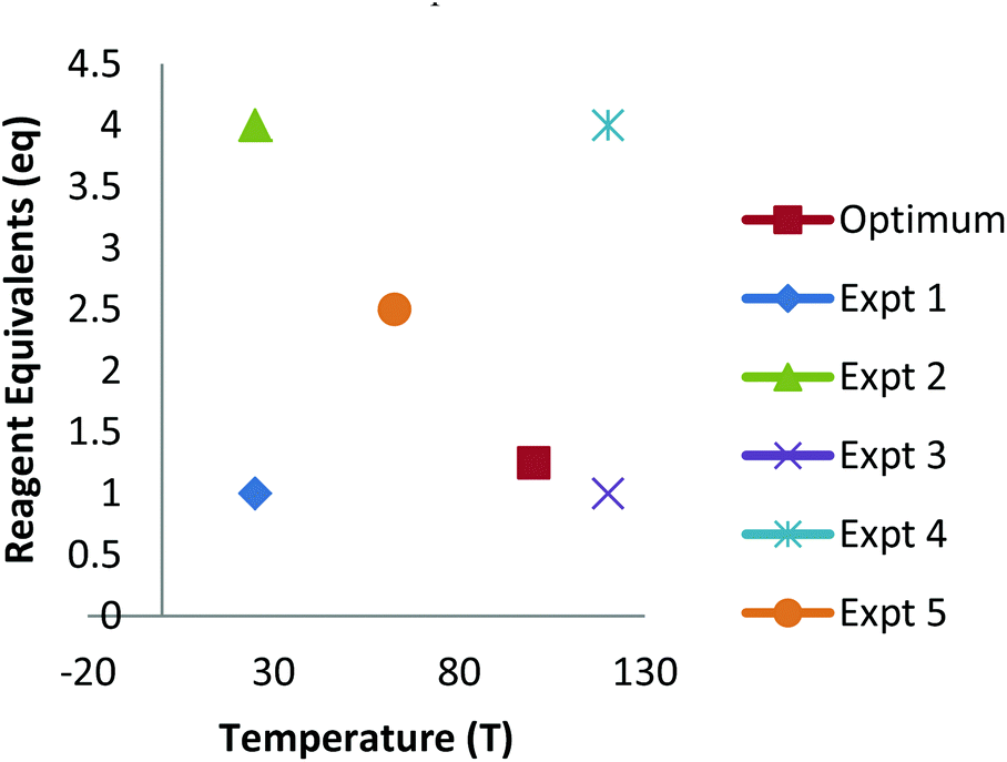
The development of new synthetic methodology is a key part of academic chemistry research, focusing both on the discovery of intrinsically novel reactions, as well as the identification of improved methods for carrying out existing transformations. Developments made in this area can ultimately determine which molecules are deemed to be ‘accessible enough’ to be suitable for a wide range of practical applications, including pharmaceuticals, agrochemicals, polymers and other functional materials, flavours/fragrances, biological probes, etc. The importance of new synthetic methodology has been recognised by the award of several Nobel prizes in recent years for the development of synthetically important reactions (asymmetric catalysis; metathesis; cross-coupling). These reactions have not only been used extremely widely by chemists in both academia and industry, but have even played a significant role in dictating which molecules are employed in many of the above applications.The uptake of novel synthetic methodology by researchers in industry and in other scientific fields is much more likely if the chemistry can be demonstrated to be ‘user friendly’. Important factors which can facilitate uptake of a particular reaction include: readily available reagents/catalysts; a wide substrate scope; good functional group compatibility; mild conditions; efficiency; sustainability and a good safety profile. However, such factors are rarely taken into account during the development of new chemistry. As noted by industrial researchers,1 many synthetic methodology papers fail to adequately explore the substrate scope of a new reaction and instead focus on reactions of largely unfunctionalised lipophilic compounds. Furthermore, despite the fact that well established statistical methods for reaction optimisation are widely used in industry,2,3 the uptake of these methods has been very low in academic chemistry.4,5 Often, the ‘optimisation’ process proceeds entirely via a trial and error approach involving the variation of one factor at a time (e.g. solvent, temperature, catalyst, concentration, etc.). This type of process can lead to researchers failing to identify ‘optimal’ conditions for a particular process if interactions between two or more factors are present.6 Thus, an attempt to optimise even two factors via a ‘one variable at a time’ (OVAT) approach can fail to find the optimum conditions if interactions between the factors are present (Fig. 1). For example, initial optimisation of an imaginary reaction via variation of the number of equivalents of reagent and the temperature involves variation of the first variable whilst keeping T = 40. This suggests that 2 equivalents of reagent give the ‘best yield’. Subsequent variation of the temperature whilst keeping eq. = 2 suggests that the optimum conditions are T = 55, eq. = 2. However, due to interaction between the factors this fails to identify the true optimum conditions where a higher yield of product can be obtained using smaller quantities of reagent (T = 105, eq. = 1.25). This is a consequence of the fact that the full reaction space has not been explored and at no-point was the combination of high T/low eq. considered.
 | ||
| Fig. 1 The pitfalls of traditional ‘one variable at a time’ (OVAT) optimisation. | ||
The technique of ‘Design of Experiments’ is a statistical approach to reaction optimisation that allows the variation of multiple factors simultaneously in order to screen ‘reaction space’ for a particular process. Importantly, this enables the evaluation of a large number of reaction parameters in a relatively small number of experiments. Whilst this technique is routinely applied by process chemists in a wide range of industries, and also by academics working in engineering disciplines,7 it is rarely used in academic chemistry. This is in spite of the fact that optimisation of particular reactions is often an extremely time-consuming part of any research project focused on the development of new synthetic methodology. A major reason for this is the lack of expertise in the use of this technique in academia which leads to a significant ‘energy barrier’. A relatively common exception is the use of DoE for reaction optimisation in projects carried out in collaboration with industrial partners.5
This pitfall shown in Fig. 1 can readily be avoided using a true DoE approach in which each vertex of reaction space is explored. In combination with a ‘centre point’ experiment this is then used to evaluate the full multi-dimensional reaction space in order to determine where the highest yield can be obtained (Fig. 2). This provides a great deal more information about the behaviour of the reaction from a similar (or potentially smaller) number of experiments than the traditional approach. The DoE study uses standard statistical techniques to model the effect of each variable (and potential interactions between variables) on the reaction outcome. A further benefit of the statistical approach, is that it can provide a built-in ‘cross-check’ of each of the individual screening reactions, enabling any anomalous results to be readily identified. In the traditional OVAT approach, repetition of each experiment is advisable to ensure reproducibility, or the entire ‘optimisation’ could be led astray by a single anomalous result.
 | ||
| Fig. 2 A DoE study covering the entire reaction space will not miss the optimum conditions provided it lies within the space covered. | ||
Optimisation of new synthetic methodology
Most new synthetic methodology development projects begin with an initial discovery (by design or by serendipity) of reaction conditions which provide the desired product in moderate yield (Table 1). This is then usually followed by an optimisation phase in which the yield of a single reaction is improved by variation of a variety of parameters. This is often extremely time consuming, as many different factors may need to be explored in order to provide good yields of the desired product from a representative substrate. Assuming experiments are performed only at high/medium/low values of each factor, this requires three experiments for each factor investigated. Once ‘optimised’ conditions are identified, they are then applied to a selection of substrates. This makes the assumption, however, that the optimised conditions for one substrate will also be the best conditions for other compounds studied. This inherently leads to the selection of substrates which are ‘similar’ to the initial one, frequently meaning that largely unfunctionalised/lipophilic molecules are explored.1 More ‘difficult’ examples (functional groups, polar molecules, sterically hindered compounds) are avoided as they do not work well under the ‘optimised conditions’, though in fact they may simply require modification of the conditions in order to give a good yield of the product.| Traditional approach | DoE approach | |
|---|---|---|

|
Initial discovery | |
| OVAT optimisation of representative example | DoE optimisation of representative example | |
| ∼3 expts per factor? | Up to 4 factors: 11 expts | |
| Up to 8 factors: 19 expts | ||
| Exploration of scope Focus on high-yielding examples | Explore the scope with a diverse range of substrates; Find limitations of the method | |
| Avoid challenging substrates that do not work under the ‘optimal conditions’ | 2nd DoE optimisation of a ‘difficult’ example to show how conditions can be adapted to accommodate more challenging compounds. | |
By switching to a DoE approach, however, much more information could be obtained about the reaction at an early stage of the project. Optimisation of the initial example via DoE should provide greater understanding of the factors underpinning the reaction from a comparable number of experiments to the traditional approach. Using a resolution IV DoE design, which can identify all important factors and determine whether interactions between factors are present or not, up to eight factors can be explored in a total of 19 experiments (including the required centre points). This also provides a good understanding of any interactions between factors that may be present. The scope of these optimised conditions could then be explored with a selection of substrates as in the traditional approach. There is no reason to expect that these conditions will be suitable for all substrates, however, especially those that contain potentially reactive functionality.
Further benefit can be obtained, therefore, by taking one of the ‘difficult’ substrates, which gives a low yield under the standard conditions, and using a second DoE process to optimise the reaction. As considerable information has already been obtained from the original optimisation, it is likely that only a few carefully chosen factors will need to be varied in order to provide improvements in the yield. This additional stage of optimisation could serve to greatly increase the potential value of the reaction. By demonstrating that the new methodology can be applied to ‘difficult’ substrates through modification of the reaction conditions, the authors will provide a much better understanding of the versatility of the new reaction that has been developed. Potential end users of the chemistry will also have a good idea how to adapt the reaction conditions to make it work for the substrates they wish to employ.
Solvent optimisation using DoE
In the case of simple quantitative factors (catalyst/reagent loading, temperature, concentration, reaction time, etc.), the use of DoE is relatively straightforward and can greatly facilitate reaction optimisation. Arguably, however, one of the most important parameters in reaction optimisation is the choice of solvent. In academia, this is traditionally done very much through a process of trial and error based on a chemist's previous laboratory experience, and may lead to the adoption of environmentally harmful and/or toxic solvents which will serve to render the resulting methodology much-less attractive to other potential users. The vast majority of new synthetic methods employ a relatively small set of common laboratory solvents during the reaction optimisation phase,‡ and therefore do not often explore the full scope of ‘solvent space’ in order to find a truly optimised procedure. The optimisation of solvent via DoE is not straightforward, however, as the suitability of a particular solvent may be a consequence of many different physical properties. This issue can be overcome, however, by the use of another statistical technique to analyse the properties of solvents. At around the same time, both Carlson and Chastrette demonstrated that principal component analysis (PCA) can be harnessed to convert a large set of solvent properties into a much smaller set of numerical parameters that enable solvents to be incorporated into an experimental design.8 This provides a ‘map’ of solvent space in which solvents with similar properties are grouped together. Solvents are then selected from different areas of the solvent map in order to explore ‘solvent space’ in the DoE. E.g. if the full range of solvents is to be explored, a solvent from each corner/vertex of the map is chosen along with a suitable centre point. This simple approach then enables the effect of each principle component on the reaction outcome to be modelled, and leads to an understanding of which area of solvent space is optimal for the reaction. Further insight can then be obtained by a more focused study of solvents within that area.This approach has been adopted by many chemists in industry, but the required PCA solvent maps are not readily available in the public domain. Industrial users typically have their own proprietary data, and solvent maps that have been published are either not targeted towards reaction optimisation (e.g. crystallisation)9 or are overly complex.10 Different solvent properties are important for different reactions, so it is important that a relatively diverse set of parameters are included. Important considerations include how solvation of compounds, reagents and catalysts is achieved, how the solvent hydrogen bonds with molecules, and how it interacts with solid materials. In this article we report a new PCA solvent map specifically designed for use in new chemistry development, and outline how this PCA map can be used for identifying alternatives to toxic/undesirable solvents and applied in combination with DoE for the optimisation of new synthetic methodology. In industry, the specific properties used in each solvent map differ from company to company, but the terms used in the map below have been found to be widely applicable in many industrial applications of PCA in DoE.
Example: optimisation of a multicomponent reaction as part of an industrial collaboration
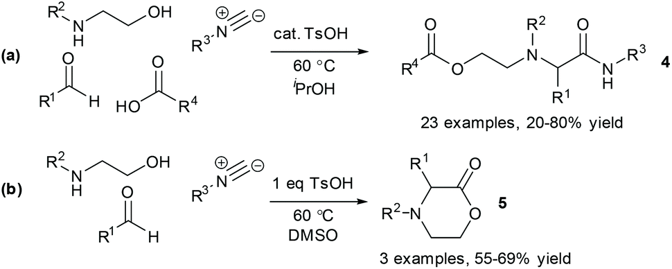
As mentioned above, DoE optimisation is sometimes used as part of industrial-academic collaborative projects when appropriate expertise is available via the industrial partner. As a representative example, we have previously made use of the technique for optimising a multicomponent reaction (MCR) of oxazolidines.11 The process was originally developed as a 3-component reaction of a pre-formed oxazolidine 1, an isocyanide 2 and a carboxylic acid 3, to give the product 4a. The initial procedure involved reaction in refluxing acetonitrile in the presence of a Brønsted acid catalyst (Scheme 1).11a Under these conditions, however, the lactone byproduct 5a was obtained in significant quantity, especially when using a 2-aryloxazolidine. In collaboration with the industrial partners for the project, a DoE optimisation was used to explore the effect of temperature, concentration, reagent loading (carboxylic acid and isocyanide), catalyst loading and solvent on the reaction outcome. | ||
| Scheme 1 DoE optimisation of a multicomponent reaction. | ||
The solvent emerged as the most significant parameter, with the originally chosen solvent (MeCN) promoting the formation of both 4a and 5a. In contrast, the formation of MCR product 4a was strongly promoted in iPrOH, which also disfavoured the formation of the lactone 5a. In addition, a higher loading of Brønsted acid catalyst was shown to promote the formation of lactone 5a, whilst having negligible effect on the formation of the desired product. Thus, by switching the solvent to iPrOH and lowering the catalyst loading the selectivity of the reaction could be improved considerably. The findings from the DoE study subsequently enabled us to identify suitable reaction conditions for carrying out the MCR as a four-component reaction in which the oxazolidinone intermediate was generated in situ from reaction of an aminoalcohol and a carbonyl compound (Scheme 2a). In a second DoE study, alternative reaction conditions (DMSO, 1 eq. TsOH) were identified to give the lactone product in the absence of the carboxylic acid component (Scheme 2b).
 | ||
| Scheme 2 Optimised conditions for the formation of the two MCR products 4 and 5. | ||
Development of a new solvent PCA map
As can be seen from the above example, the effect of solvent on a reaction outcome can be hugely important, and a DoE study can provide an excellent insight into how the choice of solvent affects the product distribution of a reaction. However, the selection of suitable solvents for a DoE study is reliant on a suitable data set which gives a good overview of ‘solvent space’ for organic chemical reactions. At present this information is not readily accessible to most researchers, making statistical optimisation of reaction solvent effectively inaccessible to many chemists. We therefore set out to address this issue by construction of a suitable solvent map for use in new reaction development.Key considerations for the choice of solvents to be included were:
1. Availability from major chemical suppliers
2. Cost
3. Boiling point/melting point
4. Diversity of properties
5. Sustainability/safety issues
We also aimed to include all solvents commonly/traditionally used in academic laboratories, even those whose use is highly undesirable (e.g. CCl4, 1,2-dichloroethane) so that suitable alternatives can readily be identified from the solvent map.
A set of 136 solvents was selected to cover a wide range of different solvent properties (Fig. 3). Approximately twenty physical (e.g. melting point, boiling point) and calculated (e.g. Hansen solubility parameters)12 properties of these solvents were then used to construct a PCA map (Fig. 4). The dataset was analysed using Umetrics SIMCA software13 to produce a principal component model. Approximately 70% of the solvent properties are modelled effectively using three principal components and 80% are modelled by four principle components (Fig. 5). Evaluation of the PCA map indicates that the first principle component correlates to a large extent with solvent polarity with non-polar solvents having high PCA1 values, and polar solvents grouped towards the lower end of the scale. Similarly, PCA2 approximately correlates with polarisability and PCA3 with hydrogen bonding properties. As can be seen from the overview of the solvent map shown in Fig. 4, there is considerably more variation in solvent properties in terms of the first two principle components with a wide distribution across solvent space (−9 < PC1 < +8; −5 < PC2 < +5). There is much less variation in the third principle component with the vast majority of solvents lying in the range −3 < PC3 < +2. In both plots, there are some notable outliers including water (136), perfluoromethylcyclohexane (117), perfluorohexane (127), trifluoroacetic acid (133) and hexafluorobenzene (84). In order to apply this type of PCA map in a DoE study, a simplistic model is used in which each principle component is modelled as a separate factor in the design. The exact PC values of the solvents are not used in the design, just their approximate position on the map. Solvents are selected to represent a high (+1) and low (−1) value of each principle component; an additional ‘centre point’ solvent is also chosen which approximately occupies the middle of the solvent space being investigated (0). Thus, to explore the full range of solvent space in three dimensions, eight solvents at the vertices of a cube are chosen, along with a single centre point (Fig. 6). A basic investigation of the effect of solvent on a reaction can be carried out effectively using only two principle components, depending on which factors (polarity, polarisability or hydrogen bonding interactions) are the most important for the reaction being studied. In this case, only five solvents are used, one from each ‘corner’ of solvent space and a centre point. In either case, the use of the solvent map to select the solvents for the DoE study ensures that they have diverse properties across the 2/3 principle components.
 | ||
| Fig. 3 List of solvents used to create the PCA solvent map. | ||
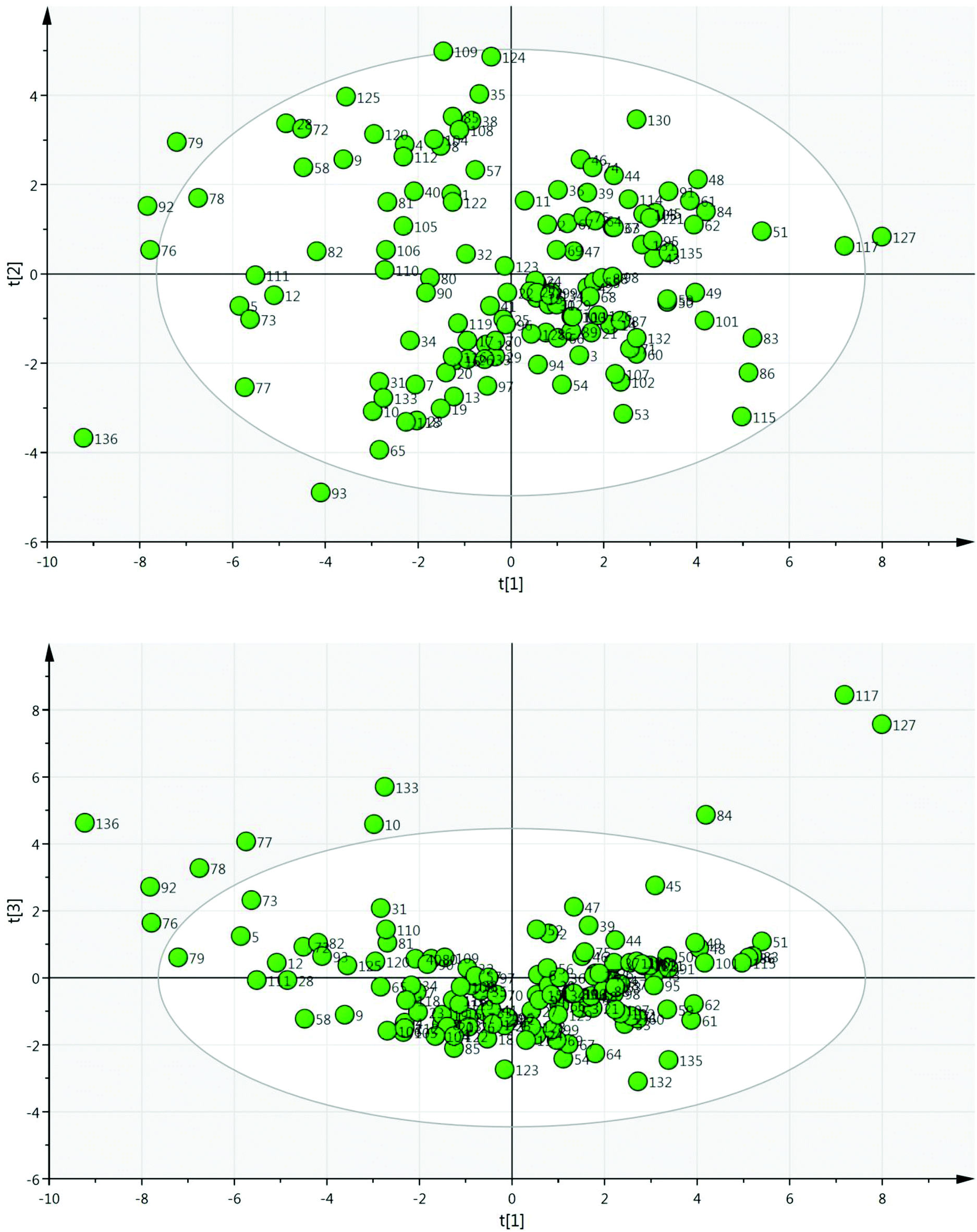 | ||
| Fig. 4 The PCA solvent map; for full details see the ESI.† | ||
 | ||
| Fig. 5 Fit of data in the model used to generate the PCA solvent map. | ||
 | ||
| Fig. 6 The use of solvent space in a DoE study requires the identification of a solvent approximately located at each vertex of a cube spanning the area of solvent space to be investigated. | ||
Suitable solvents on the PCA map which can be used as the vertices for a full exploration of solvent space, or corner points for a two-dimensional study of the first two principle components are shown in Table 2. Alternatively, only a subsection of solvent space can be explored: e.g. polar aprotic solvents; non-polar solvents. This can be achieved by selecting solvents at the vertices of a distorted cuboid (or corners of a distorted rectangle) covering the relevant area of solvent space.
| Corner | Vertex | Solvent |
|---|---|---|
| 0 | 0 | 1,4-Dioxane (6); 2-ethyl-1-butanol (15); 4-methyltetrahydropyran (30); acetic anhydride (32); methyl isobutyrate (100); toluene (131); trimethyl orthoformate (134); 3-pentanone (27); butanenitrile (41); butyl acetate (42); ethyl butanoate (68); n-propyl acetate (113) |
| 1 | 1 | 2-Butanol (13); 2-methyl-1-butanol (18); 2-methyl-1-pentanol (17); 2-methylpropan-1-ol (19); 2-methylpropan-2-ol (20); 2-propanol (23); 3-pentanol (26); 1-pentanol (116); 1-propanol (118); propionitrile (119) |
| 2 | 1,3-Propanediol (5); 2,2,2-trifluoroethanol (10); acetic acid (31); ethylene glycol (73); formic acid (77); methanol (93); trifluoroacetic acid (133); water (136) | |
| 2 | 3 | 1,1,3,3-Tetramethylurea (1); 1,3-dimethylimidazolidin-2-one (4); 1-ethyl-2-pyrrolidinone (8); 1-methylimidazole (9); dimethylsulfoxide (58); hexamethylphosphoramide (85); N,N′-dimethylpropyleneurea (104); N,N-dimethylacetamide (105); N-methylpyrrolidine-2-one (112); pyridine (122) |
| 4 | Benzyl alcohol (40); ethylene carbonate (72); formamide (76); glycerol (78); glycerol carbonate (79); glycerol-1-monobutylether (81); methanesulfonic acid (92); nitrobenzene (109); propylene carbonate (120); sulfolane (125) | |
| 3 | 5 | 1,2-Dimethoxyethane (3); 2-methyltetrahydrofuran (21); diethyl ether (53); diethylamine (54); di-n-propylether (60); ethyl n-butyl ether (71); methyl-t-butyl ether (102); n-butyl methyl ether (107); trimethylamine (132) |
| 6 | Heptane (83); hexane (86); methylcyclohexane (101); pentane (115); tert-butyl acetate (126) | |
| 4 | 7 | Dipentene (limonene) (61); di-tert-butyl ketone (64); ethyl amyl ketone (67); dipentyl ether (62) |
| 8 | Benzene (37); benzotrifluoride (39); carbon disulphide (44); carbon tetrachloride (45); chlorobenzene (46); cis-decalin (48); decane (51); fluorobenzene (75); hexafluorobenzene (84); mesitylene (91); m-xylene (103); o-xylene (114); perfluoromethylcyclohexane (117); p-xylene (121); tetradecafluorohexane (127); tetralin (130). |
Applications of the solvent map: solvent substitutions
The choice of a solvent for a chemical reaction has a major impact on the environmental impact of the process. Typically, solvent accounts for a significant proportion of the waste produced during a chemical synthesis, and has a major impact on the energy used, both during the reaction itself and during removal/recovery of the solvent after the reaction. As a consequence, the selection of solvents for industrial processes is highly important. Consequently, many different solvent selection guides have been reported by industrial researchers,14 which take into account a range of important factors including toxicity, safety, environmental impact, ease of recycling/recovery, and sustainability.15 It has also been noted that the solvents selected for use by medicinal chemists at an early stage of the drug discovery pipeline influence the solvents employed in subsequent process chemistry scale-up routes, and the pharmaceutical industry has made a considerable effort to encourage medicinal chemists to make use of greener and safer solvents when preparing drug candidate molecules. It would also be beneficial if academic chemists involved in the development of new synthetic methodology were to take these considerations into account, and explore the use of potentially safer alternative solvents rather than routinely relying on a limited range of ‘traditional’ solvents.A simple application of the solvent map is to identify alternative solvents for a reaction of interest. This can be particularly useful for substituting highly toxic or otherwise undesirable solvents. In Table 3, a list of potential substitutes for a selection of hazardous solvents is provided. Thus, carbon tetrachloride, which is still often used in radical reactions despite being heavily restricted as an ozone-depleting chemical, can potentially be substituted with trifluorotoluene. Similarly, trifluorotoluene or fluorobenzene can also be used as alternatives to the toxic solvents chloroform and 1,2-dichloroethane, the latter often being used in a variety of metal-catalysed transformations as a higher boiling point alternative to dichloromethane. A number of more attractive alternatives to dichloromethane itself can also be identified from the map including 1,4-dioxane, 4-methyltetrahydropyran and dimethyl carbonate, the latter having very good environmental credentials.16 A selection of alternatives to benzene and to dipolar aprotic solvents such as DMF, DMSO and HMPA are also provided, though it is acknowledged that many of these alternatives are already widely used in this context.
| Solvent | Possible alternatives |
|---|---|
| CH2Cl2 (52) | 1,4-Dioxane (6) |
| Dimethyl carbonate (56) | |
| 4-Methyltetrahydropyran (30) | |
| CHCl3 (47) | Fluorobenzene (75) |
| Trifluorotoluene (39) | |
| Cl(CH2)2Cl (2) | Fluorobenzene (75) |
| Trifluorotoluene (39) | |
| CCl4 (45) | Trifluorotoluene (39) |
| Decalin (48) | |
| p-Xylene (121) | |
| Benzene (37) | m-Xylene (103) |
| o-Xylene (114) | |
| Toluene (131) | |
| Fluorobenzene (75) | |
| Dipropylene glycol dimethyl ether (63) | |
| DMSO (58) | 1-Methylimidazole (9) |
| 4-Formylmorpholine (28) | |
| N-Methylpyrrolidinone (112) | |
| 1,3-Dimethylimidazolidin-2-one (4) | |
| Ethylene carbonate (72) | |
| DMF (106) | N,N-Dimethylacetamide (105) |
| Pyridine (122) | |
| Tetramethylurea (1) | |
| N-Methylpyrrolidinone (112) | |
| 1-Methylimidazole (9) | |
| HMPA (85) | DMPU (104) |
| 1-Ethyl-2-pyrrolidinone (8) | |
| 1,3-Dimethylimidazolidin2-one (4) | |
| N-Methylpyrrolidinone (112) | |
| Quinoline (124) |
In order to test the use of the solvent map for substituting chlorinated solvents, we explored alternative solvents for some recently developed gold-catalysed reactions (Scheme 3). The gold-catalysed cyclisation of alkynyl boronic acid 6 to boron enolate 7, originally developed in dichloromethane,17 was shown to take place equally effectively in dimethyl carbonate, a solvent with a considerably better safety profile (a). Similarly, the gold-catalysed hydroamination of cyclohexadiene 8, originally reported in 1,2-dichloroethane,18 could be carried out effectively in trifluorotoluene or fluorobenzene, the latter proving to be a much better solvent for this particular reaction (b). In both of the solvent substitution reactions shown in Scheme 3, no significant lowering of the reaction yield was observed on replacing the undesirable solvent with a safer/greener alternative. This suggests that these alternatives to chlorinated solvents should be routinely screened by researchers during reaction development, as this could significantly reduce the use of chlorinated solvents by their avoidance at an early stage of the process.
 | ||
Scheme 3 Replacement of toxic/hazardous chlorinated solvents with safer alternatives; a![[thin space (1/6-em)]](https://www.rsc.org/images/entities/char_2009.gif) isolated yield; b1H NMR yield using an internal standard. isolated yield; b1H NMR yield using an internal standard. | ||
Case study – DoE optimisation of an SNAr reaction
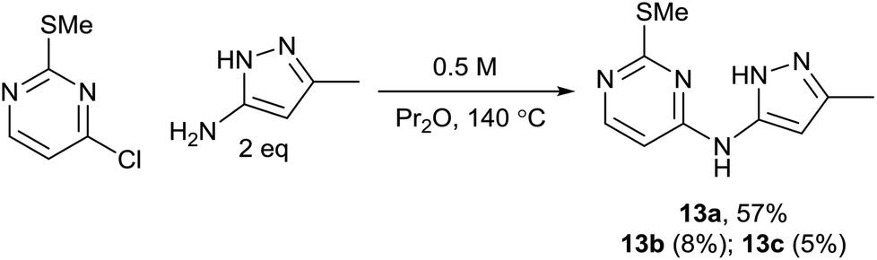
As part of an ongoing medicinal chemistry project, we needed to carry out the reaction of 4-chloropyrimidine 11 and 3-aminopyrazole 12 to give 13a (Scheme 4). A closely related literature procedure was used as a basis for carrying out the reaction, using DIPEA as a base and NaI as an additive in DMF.20 Microwave heating at high temperature was used to give a reasonable conversion of the starting materials, but this led to formation of multiple reaction products. As well as the desired product 13a, the two regioisomeric SNAr products 13b§ and 13c§ were also formed alongside an initially unidentified byproduct 13d. This was later determined to be the product of an SNAr reaction between dimethylamine (generated from decomposition of DMF at high temperature) and the chloropyrimidine 11. In all of the experiments carried out in the initial study, the isolated yield of product 13a obtained was less than 20%. | ||
| Scheme 4 DoE optimisation of an SNAr reaction in DMF. | ||
The selection of factors and ranges for a DoE study is of great importance, as poor choices can limit the utility of the exercise. Thus, it is essential to select wide-enough ranges for each factor which enable the design to explore a sufficiently large area of ‘reaction space’. However, for useful information to be gained, the reaction should still work (i.e. give a non-zero yield of the product) at the extreme edges of the design space. For an initial DoE study,21 we elected to examine the effect of varying the quantity of 12, DIPEA (1–5 eq.) and sodium iodide (0.1–2.0 eq.), alongside the reaction concentration (2–5 mL of DMF) and the temperature (120–200 °C). This was carried out via a total of 16 experiments plus three centre points to enable the effect of the factors to be determined. This enabled the factors favouring the formation of each of the different reaction products to be elucidated. The centre points are three reactions performed under identical conditions at the centre of the design space (i.e. the mid-point of all of the factor ranges) which provide an indication of the reproducibility of the reaction. Performing the reaction under identical conditions should of course give an identical outcome, but there are inevitably some errors in the experimental/analytical procedures which can lead to variation of the yields. It is therefore important to plan the design carefully to minimise any potential errors. For example, preparing a solution of a reagent of known concentration and dispensing appropriate volumes of this solution into each experiment will generally provide much greater accuracy than weighing out reagents for each reaction separately. In our case, stock solutions of 11 and 12 were prepared in order to minimise any variation in the amount of limiting reagent present in each reaction. Similarly, it is important to identify a reproducible method for measuring the yield. Early experiments demonstrated that the aqueous work-up of this reaction led to considerable variation in yield of the products 13a–13d, so in the DoE study all reactions were concentrated directly under vacuum prior to analysis of the crude residue by NMR using an internal standard. For the three centre points this gave fairly consistent yields, as can be seen in Fig. 7 which illustrates the much smaller variation in the replicate experiments (blue) in comparison to the other reactions (green) in terms of the yield of 13a observed.
 | ||
| Fig. 7 Variation in the yield of 13a across the 19 experiments in the DoE. | ||
Analysis of the results provides details of which factors affect the yield of the desired product 13a. These are illustrated by the coefficient plot shown in Fig. 8. Each green bar represents a significant factor in the reaction, illustrating the average effect on the yield of 13a on increasing the factor from the mid-point of the design to the highest value in the design. Thus, the most significant factor in the yield of 13a is the temperature, with the higher temperature (200 °C) giving on average a 2.5% increase in the yield. Notably, increasing the amount of NaI to 2 eq. leads, on average, to a 2% decrease in the yield of 13a, whilst increasing the amount of DMF leads to a 1.7% decrease.
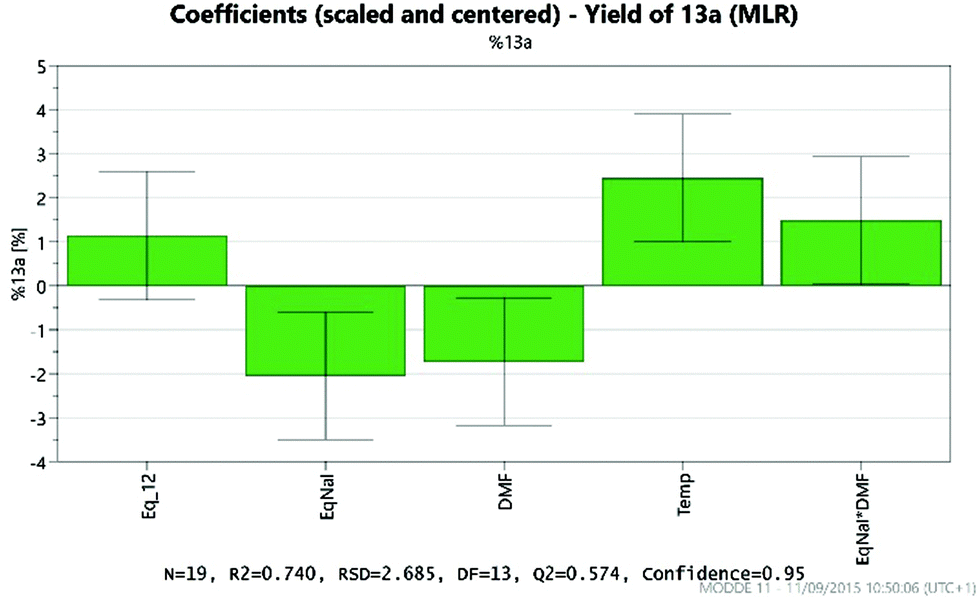 | ||
| Fig. 8 Factors affecting the yield of 13a obtained. | ||
The factors affecting the yields of each of the products 13a–13d are shown in Table 4. As expected, the NaI additive was not beneficial for the formation of the desired product 13a, and this was therefore omitted from subsequent reactions. Interestingly, the formation of the regioisomeric SNAr products 13b–13c is favoured by increasing the quantity of base used in the reaction, whereas the formation of the desired product 13a is largely unaffected by the amount of base. Furthermore, there is an interaction between the quantity of base used and the temperature: increasing the quantity of base leads to a much larger quantity of the side products 13b and 13c at higher temperature. It was therefore concluded that removing the DIPEA entirely in future reactions would be beneficial both in terms of improving the selectivity of the reaction and facilitating purification. During the course of this initial DoE study, a pure sample of the byproduct 13d was isolated and the structure confirmed. This byproduct is evidently formed through thermal decomposition of the solvent to generate dimethylamine which then undergoes an SNAr reaction with the chloropyrimidine 11. A switch in solvent was therefore necessary to avoid the formation of 13d, and we elected to make use of our newly developed PCA solvent map to evaluate an area of solvent space for this transformation, alongside temperature and concentration as the other important variables. We chose to incorporate solvent as a two-dimensional parameter in the design to provide a useful preliminary insight into the effect of the main two solvent principle components on the reaction (t1 and t2). Although these first two principle components only accurately model 55% of the original solvent properties, this is sufficient to provide an insight into which areas of solvent space are suitable for a particular reaction, and a further more detailed solvent optimisation can then be carried out subsequently if required. Solvents were selected approximately in each quadrant of the map, taking into account the temperature range to be studied, their compatibility with microwave heating and their ability to solubilise the reagents. Dimethylacetamide (105), 1-butanol (7), cyclopentyl methyl ether (50) and dipropyl ether (60) were selected as ‘corner’ points, with propionitrile (119) as a centre point (Fig. 9).
 | ||
| Fig. 9 Solvents selected for screening in the second DoE study. | ||
| Product | Favoured by | Disfavoured by |
|---|---|---|
| 13a | Increasing temp. | Increasing NaI |
| Increasing solvent vol. | ||
| 13b | Increasing base | |
| Increasing temp. | ||
| 13c | Increasing base | |
| Increasing temp. | ||
| 13d | Increasing temp. | Increasing NaI |
| Increasing base |
The DoE study also included temperature (100–140 °C) and concentration (0.1–0.5 M) as factors, and this required a total of eight experiments plus three centre points to give a resolution IV design in which individual factors are well resolved but interactions between factors are confounded.
As expected, the solvolysis product 13d was not observed in most solvents although it was still formed in one of the high temperature reactions carried out in DMA. An excellent model was obtained using multiple linear regression (MLR) for predicting the yield of the desired product 13a (Fig. 10). The factors affecting the yield of 13a are shown in the coefficient plot (Fig. 11). Temperature and concentration are the most significant factors, with higher temperature and higher concentration leading to an improvement in yield as might be expected. The interactions between factors are not fully resolved using a resolution IV design, so care must be taken in interpreting the results. The solvent dependence is somewhat complicated, with the two principle components potentially showing a significant interaction (though as the interactions are not resolved this interaction between t1 and t2 is confounded with the interaction between temperature and concentration; similarly the interaction between t1 and concentration is confounded with the interaction between t2 and temperature). However, subsequent preparative experiments confirmed that the solvent was an important factor.22 Thus, whilst neither principle component is very important as a factor in its own right, there is a strong interaction with the most favourable areas of solvent space being either high t1/low t2 or low t1/high t2. This interaction is illustrated by the plot in Fig. 12. This suggests that either DMA or Pr2O are preferable for the reaction, with the latter being slightly more effective – a somewhat unusual choice of solvent for an SNAr reaction! Furthermore, it was observed that the product 13a (and unreacted amine 12) often precipitated out of Pr2O at the end of the reaction, facilitating purification of the product. Satisfyingly, by carrying out the reaction at high concentration/temperature in Pr2O, a 57% isolated yield of product 13a was obtained (Scheme 5), along with small amounts of products 13b and 13c (and 13% recovered starting material). This gave material in sufficient quantity and purity for the project, so no further optimisation was carried out from this point onwards.
 | ||
| Fig. 10 Fit of the model obtained for the DoE for the yield of 13a. | ||
 | ||
| Fig. 11 Coefficient plot generated from the MODDE experimental design showing the factors influencing the yield of 13a. | ||
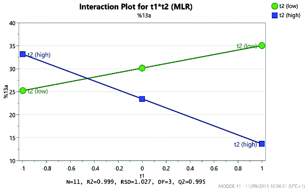 | ||
| Fig. 12 Graph showing the interaction between the two solvent principle components (t1 and t2). | ||
 | ||
| Scheme 5 Optimised procedure for the SNAr reaction in Pr2O. | ||
Conclusions
The potential benefits of the ‘Design of Experiments’ approach to reaction optimisation for the development of new methodology have been discussed, with a discussion of how the technique can be applied to reactions during their development. A new PCA solvent map has been developed specifically for use in new reaction development incorporating 136 solvents which offer a wide range of different properties. The application of the new PCA solvent map for identifying alternatives to toxic chlorinated solvents has been demonstrated, and it has also been used in the DoE optimisation of an SNAr reaction. Interestingly, it was demonstrated that this reaction works well in solvents in opposite corners of the solvent map – DMA or Pr2O. The latter choice was shown to be highly effective both for effective reaction and for ease of purification of the SNAr product, and would most likely not have been considered a viable solvent to test in a traditional ‘optimisation’ study.Acknowledgements
We would like to acknowledge the Engineering and Physical Sciences Research Council (postdoctoral funding for LB, grant reference EP/K001183/1 and the EPSRC Dial-a-Molecule Network for financial support to TDS/PMM) for financial support. We would also like to thank the UCL PhD Program in Drug Discovery for a PhD studentship (awarded to FB).Notes and references
- A. Nadin, C. Hattotuwagama and I. Churcher, Angew. Chem., Int. Ed., 2012, 51, 1114–1122 CrossRef CAS PubMed.
- (a) P. M. Murray, S. N. G. Tyler and J. D. Moseley, Org. Process Res. Dev., 2013, 17, 40–46 CrossRef CAS; (b) S. A. Weissman and N. G. Anderson, Org. Process Res. Dev., 2015, 19, 1605–1633 CrossRef CAS; (c) D. Lendrem, M. Owen and S. Godbert, Org. Process Res. Dev., 2001, 5, 324–327 CrossRef CAS.
- (a) H. Tye and M. Whittaker, Org. Biomol. Chem., 2004, 2, 813–815 RSC; (b) S. Stone, T. Wang, J. Liang, J. Cochran, J. Green and W. Gu, Org. Biomol. Chem., 2015, 13, 10471–10476 RSC; (c) G. Guercio, A. Perboni, F. Tinazzi, L. Rovatti and S. Provera, Org. Process Res. Dev., 2010, 14, 840–848 CrossRef CAS.
- (a) N. Caldwell, C. Jamieson, I. Simpson and A. J. B. Watson, ACS Sustainable Chem. Eng., 2013, 1, 1339–1344 CrossRef CAS; (b) A. L. García-Cabeza, R. Marín-Barrios, R. Azarken, F. J. Moreno-Dorado, M. J. Ortega, H. Vidal, J. M. Gatica, G. M. Massanet and F. M. Guerra, Eur. J. Org. Chem., 2013, 8307–8314 CrossRef; (c) C. C. Perez, J. M. Pena and C. R. D. Correia, New J. Chem., 2014, 38, 3933–3938 RSC; (d) A. R. Alimardanov, M. T. Barrila, F. R. Busch, J. J. Carey, M. A. Couturier and C. Cui, Org. Process Res. Dev., 2004, 8, 834–837 CrossRef CAS; (e) V. Karaluka, R. M. Lanigan, P. M. Murray, M. Badland and T. D. Sheppard, Org. Biomol. Chem., 2015, 13, 10888–10894 RSC.
- (a) P. Renzi, C. Kronig, A. Carlone, S. Eröksüz, A. Berkessel and M. Bella, Chem. – Eur. J., 2014, 20, 11768–11775 CrossRef CAS PubMed; (b) A. Ekebergh, C. Lingblom, P. Sandin, C. Wennerås and J. Mårtensson, Org. Biomol. Chem., 2015, 13, 3382–3392 RSC; (c) V. Hajzer, P. Alexy, A. Latika, J. Durmis and R. Šebesta, Monatsh. Chem., 2015, 146, 1541–1545 CrossRef CAS; (d) C. Jamieson, M. S. Congreve, D. F. Emiabata-Smith, S. V. Ley and J. J. Scicinski, Org. Process Res. Dev., 2002, 6, 823–825 CrossRef CAS; (e) C. Jamieson, M. S. Congreve, D. F. Emiabata-Smith and S. V. Ley, Synlett, 2000, 1603–1607 CAS; (f) M. D. Evans, J. Ring, A. Schoen, A. Bell, P. Edwards, D. Berthelot, R. Nicewonger and C. M. Baldino, Tetrahedron Lett., 2003, 44, 9337–9341 CrossRef CAS; (g) T. N. Glasnow, H. Tye and C. O. Kappe, Tetrahedron, 2008, 64, 2035–2041 CrossRef; (h) See also ref 11b.
- (a) R. Leardi, Anal. Chim. Acta, 2009, 652, 161–172 CrossRef CAS PubMed; (b) R. Carlson and T. Hudlicky, Helv. Chim. Acta, 2012, 95, 2052–2062 CrossRef CAS.
- (a) C. Grant, A. C. da Silva Damas Pinto, H.-P. Lui, J. M. Woodley and F. Baganz, Biotechnol. Bioeng., 2012, 109, 2179–2189 CrossRef CAS PubMed; (b) R. S. Islam, D. Tisi, M. S. Levy and G. J. Lye, Biotechnol. Prog., 2007, 23, 785–793 CrossRef CAS PubMed.
- (a) R. Carlson, T. Lundstedt and C. Albano, Acta Chem. Scand., Ser. B, 1985, 39, 79–91 CrossRef; (b) M. Chastrette, M. Rajzmann, M. Chanon and K. F. Purcell, J. Am. Chem. Soc., 1985, 107, 1–11 CrossRef CAS; (c) R. Carlson and J. E. Carlson, Org. Process Res. Dev., 2005, 9, 680–689 CrossRef CAS.
- (a) M. Allesø, F. van den Berg, C. Cornett, F. Steen Jørgensen, B. Halling-Sørensen, H. Lopez de Diego, L. Hovgaard, J. Aaltonen and J. Rantanen, J. Pharm. Sci., 2008, 97, 2145–2159 CrossRef PubMed; (b) M. Allesø, J. Rantanen, J. Aaltonen, C. Cornett and F. van den Berg, J. Chemom., 2008, 22, 621–631 CrossRef.
- A. R. Katrizky, D. C. Fara, M. Kuanar, E. Hur and M. Karelson, J. Phys. Chem. A, 2005, 109, 10323–10341 CrossRef PubMed.
- (a) L. J. Diorazio, W. B. Motherwell, T. D. Sheppard and R. W. Waller, Synlett, 2006, 2281–2283 CAS; (b) R. W. Waller, L. J. Diorazio, B. A. Taylor, W. B. Motherwell and T. D. Sheppard, Tetrahedron, 2010, 66, 6496–6507 CrossRef CAS.
- Hansen Solubility Parameters: A User's Handbook, CRC Press, Inc., Boca Raton, Florida, 2007 Search PubMed.
- The PCA solvent map was developed using SIMCA software, available from Umetrics; http://www.umetrics.com/products/simca (accessed 24th November 2015).
- For articles discussing the selection of less toxic/hazardous solvents, see: (a) D. S. MacMillan, J. Murray, H. F. Sneddon, C. Jamieson and A. J. B. Watson, Green Chem., 2013, 15, 596–600 RSC; (b) H. E. Eastman, C. Jamieson and A. J. B. Watson, Aldrichimica Acta, 2015, 48, 51–55 Search PubMed; (c) D. Prat, A. Wells, J. Hayler, H. Sneddon, C. R. McElroy, S. Abou-Shehada and P. J. Dunn, Green Chem., 2015, 45 10.1039/c5gc01008j; (d) A. Benazzouz, L. Moity, C. Pierlot, M. Sergent, V. Molinier and J.-M. Aubry, Ind. Eng. Chem. Res., 2013, 52, 16585–16597 CrossRef CAS; (e) D. Prat, O. Pardigon, H.-W. Flemming, S. Letestu, V. Ducandas, P. Isnard, E. Guntrum, T. Senac, S. Ruisseau, P. Cruciani and P. Hosek, Org. Process Res. Dev., 2013, 17, 1517–1525 CrossRef CAS; (f) D. Prat, J. Hayler and A. Wells, Green Chem., 2014, 16, 4546–4551 RSC; (g) R. K. Henderson, C. Jiménez-González, D. J. C. Constable, S. R. Alston, G. G. A. Inglis, G. Fisher, J. Sherwood, S. P. Binks and A. D. Curzons, Green Chem., 2011, 13, 854–862 RSC.
- (a) P. G. Jessop, Green Chem., 2011, 13, 1391–1398 RSC; (b) C. Jiménez-González, A. D. Curzons, D. J. C. Constable and V. L. Cunningham, Clean Technol. Environ. Policy, 2005, 7, 42–50 CrossRef.
- (a) See ref. 14g; ; (b) T. Laird, Org. Process Res. Dev., 2012, 16, 1–2 CrossRef CAS; (c) R. W. Foster, L. Benhamou, M. J. Porter, D.-K. Bučar, H. C. Hailes, C. J. Tame and T. D. Sheppard, Chem. – Eur. J., 2015, 21, 6107–6114 CrossRef CAS PubMed.
- C. Körner, P. Starkov and T. D. Sheppard, J. Am. Chem. Soc., 2010, 132, 5968–5969 CrossRef PubMed.
- C. Brouwer and C. He, Angew. Chem., Int. Ed., 2006, 45, 1744–1747 CrossRef CAS PubMed.
- Nearest neighbours on the PCA solvent map were identified using the free online PRISM PCA Visualiser available at http://www.prismtc.co.uk/pca-3d-visualiser/ (accessed 24th November 2015).
- J.-D. Charrier, F. Mazzei, D. Kay and A. Miller, Processes for preparing substituted pyrimidines and pyrimidine derivatives as inhibitors of protein kinase, WO2004000833, 2004 Search PubMed.
- The DoE optimisation was designed and analysed using MODDE 10 software, available from Umetrics; http://www.umetrics.com/products/modde (accessed 24th November 2015).
- High yields of 13a were only obtained in either di-n-propyl ether or N,N-dimethylacetamide, with CPME giving consistently low yields. This is consistent with the interaction between t1 and t2 shown in Fig. 12.
Footnotes |
| † Electronic supplementary information (ESI) available: Principle component values for the new PCA solvent map, experimental procedures, spectroscopic data and 1H and 13C NMR spectra. CCDC 1423524 and 1423525. For ESI and crystallographic data in CIF or other electronic format see DOI: 10.1039/C5OB01892G |
| ‡ Arguably, most reactions that are developed use one of the following ten common laboratory solvents: Et2O, THF, MeCN, DMF, DMSO, EtOH, MeOH, CH2Cl2, PhMe and acetone. |
| § CCDC 1423524 and 1423525 contain the supplementary crystallographic data for compounds 13b and 13c. |
| This journal is © The Royal Society of Chemistry 2016 |