 Open Access Article
Direct fabrication of complex 3D hierarchical nanostructures by reactive ion etching of hollow sphere colloidal crystals†
Kuo
Zhong
*a,
Jiaqi
Li
bc,
Stijn
Van Cleuvenbergen
a and
Koen
Clays
*a
aDepartment of Chemistry, KU Leuven, Celestijnenlaan 200D, B-3001 Leuven, Belgium. E-mail: kuo.zhong@chem.kuleuven.be; koen.clays@fys.kuleuven.be
bIMEC, Kapeldreef 75, B-3001 Leuven, Belgium
cLaboratory of Solid-State Physics and Magnetism, Department of Physics and Astronomy, KU Leuven, Celestijnenlaan 200D, B-3001 Leuven, Belgium
First published on 9th August 2016
Abstract
Direct reactive ion etching (RIE) of hollow SiO2 sphere colloidal crystals (HSCCs) is employed as a facile, low-cost method to fabricate complex three-dimensional (3D) hierarchical nanostructures. These multilayered structures are gradually transformed into nanostructures of increasing complexity by controlling the etching time, without complicated procedures (no mask needed). The resulting 3D topologies are unique, and cannot be obtained through traditional approaches. The formation mechanism of these structures is explained in detail by geometrical modeling during the different etching stages, through shadow effects of the higher layers. SEM images confirm the modeled morphological changes. The nanostructures obtained by our approach show very fine features as small as ∼30 nm. Our approach opens new avenues to directly obtain complex 3D nanostructures from colloidal crystals and can find applications in sensing, templating, and catalysis where fine tuning the specific surface might be critical.
Three-dimensional (3D) nanostructures have attracted a lot of research interest due to their unique applications in nanofiltration,1,2 photonics,3,4 phononic crystals,5 sensors,6 templates,7 and catalysis.8 Various classical “top-down” approaches have been explored to fabricate 3D nanostructures from homogeneous bulk materials, such as deep UV photolithography,1 holography9 and electron-beam lithography.10 Yet these methods involve time-consuming, costly and complex processes, in particular when producing large area patterns. “Bottom-up” approaches based on self-assembly of colloidal spheres into 3D nanostructures, termed colloidal crystals (CCs), provide an alternative approach.11–15 While this methodology is straightforward, the self-assembled products are traditionally limited in terms of morphology, as it is still difficult to reshape the spherical colloidal building blocks even after post-treatment.16–21
In an effort to develop new strategies to create nanostructures with complex morphologies, a 3D patterning technique based on colloidal array masks has recently drawn a lot of attention. It employs self-assembled colloidal arrays as a mask to fabricate complex nanostructures through RIE etching,22–27 evaporation,22 or UV illumination.28–30 References note that RIE has been used on colloidal particles in electrospun fibers as a means to obtain individual anisotropic particles.31 The RIE and evaporation methods use a 2D CC array as a shadow mask, making it difficult to produce complex 3D nanostructures; the UV illumination uses CCs as a phase-shift element to generate a 3D light intensity distribution. However, these methods still involve relatively complex fabrication processes, such as preparation of the colloidal mask and anti-reflection treatment of the substrate. More convenient strategies, in terms of both cost and simplicity, are desirable. Recently, we developed a new type of nanosphere lithography to directly create nanorings by means of reactive ion etching of monolayers of hollow SiO2 spheres,32 which could be attributed to preferential etching of the top and bottom surfaces of the hollow spheres.
In this work, we extend this approach to fabricate complex 3D hierarchical nanostructures directly from multilayered hollow silica sphere colloidal crystals (HSCCs) using RIE. Because the shadow effect originates from the upper layers and interstices of the structure itself no extra mask is needed. The resulting 3D hierarchical nanostructures with feature sizes as small as ∼30 nm are impressively complex and unique, in comparison to the simplicity of our method. The high resolution in the obtained 3D nanostructures constructed by this approach is comparable to that of electron beam lithography. To the best of our knowledge, we are the first to successfully create such complex 3D nanostructures by direct etching of HSCCs, with potential applications in nanofabrication or as nanophotonic devices. Our strategy not only diversifies the colloidal lithography, but also opens new avenues to utilize the hollow spheres which are different from their conventional applications.33–35
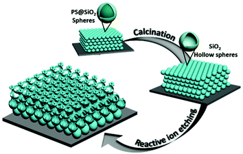
The straightforward fabrication process is illustrated in Fig. 1. First, silica coated polystyrene core–shell spheres (PS@SiO2) were used to fabricate CCs via convective self-assembly.36 The PS@SiO2 core–shell spheres were synthesized as described in the literature.37 After calcination, the PS@SiO2 CCs were transformed into HSCCs by the removal of the PS cores. Finally, complex 3D hierarchical nanostructures were obtained by direct etching of HSCCs via RIE, in which a sulphur hexafluoride (SF6) flow of 25 sccm at a pressure of ∼20 mTorr and forward and ICP power of 5 W and 150 W, respectively was applied. This etching process gradually changes the morphology of the HSCCs.
 | ||
| Fig. 1 Schematic illustration of the fabrication process for producing 3D hierarchical nanostructures by direct etching of hollow SiO2 sphere colloidal crystals via reactive ion etching. | ||
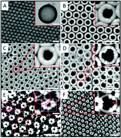
Fig. 2A shows a SEM image of the sintered HSCCs showing good ordered close-packed structures with their (111) crystal plane parallel to the substrate. The structures of hollow SiO2 spheres with a diameter of ∼272 nm and a shell thickness of ∼25 nm were confirmed by TEM, as shown in the inset of Fig. 2A. After a short etching time (2 min), the top surface of the first layer of hollow spheres of HSCCs was broken and a small hole appears, changing from hollow spheres to bowl-shaped nanostructures as shown in Fig. 2B. When the etching time is further increased to 4 min, the bottom of the first layer spheres is also opened, as confirmed by SEM (Fig. 2C). At this point the triangle interstices between the spheres of the second layer become visible, as is clear from the zoom-in SEM image inset of Fig. 2C. Upon further etching, the morphology of the first layer spheres is transformed into ring-shaped structures as shown in Fig. 2D. These morphological changes are consistent with our previously reported results.32 They result from preferential etching of the top and bottom surfaces of the hollow sphere under the unidirectional plasma field. At the same time we also see from the magnified SEM image in the inset of Fig. 2D that the second layer of spheres is simultaneously etched. Increasing the etching time to 8 min, the morphology of the first and the second layer of hollow spheres is further transformed from ring-shaped to nanodot-shaped and hollow cage-shaped nanostructures, respectively, see Fig. 2E. The hexagonal petal-like structures, circled by a white box in the SEM image, are the residual parts of three neighboring hollow spheres of the first layer as indicated by pink circles. Meanwhile the hollow spheres in the second layer transform into nanocages, see the inset of Fig. 2E for a detailed view. When the etching time is 9 min the hexagonal petals are still observed (see Fig. 2F), while the morphology of the second layer is transformed into hemicage-shaped nanostructures (inset Fig. 2F). The obtained 3D complex nanostructures result from the shadow effect. Therefore, the morphology of the hierarchical nanostructure is not dependent on the size of the hollow spheres.
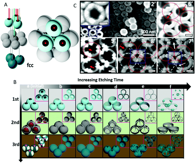
In order to investigate the formation mechanism of these complex 3D hierarchical nanostructures in more detail, an fcc unit cell model was employed as shown in Fig. 3A. Colloidal spheres can be self-assembled into both fcc and hcp crystal structures, but favor the formation of thermodynamically stable fcc structures.38 To simplify the explanations, we assume that the CCs exist as fcc structures, so that the sequence of stacked layers alternates as “ABCABC…”, see Fig. 3A (right panel). During the RIE process, the reaction occurs in a chamber employing a unidirectional electric field to guide the reactive species vertically to the sample surface, hence the top surface of the spheres is etched preferentially.32,39,40 At the same time the first layer functions as a shadow mask and etching of the layers below occurs through the interstices of the first layer. In practice however, only two layers of spheres are etched simultaneously, since the flow rate of the reactive species is reduced inside the CC structures.24
During the etching process, the hollow spheres in the different layers undergo several phases of morphological changes. This is schematically described in Fig. 3B, where a series of typical morphologies is displayed to visualize the structural evolution. Column a represents the initial unetched state, where black, red and white areas denote the regions which will be etched in the process. The colors indicate which regions will be etched simultaneously depending on the (time-dependent) shadow effect from the upper layer spheres. Black regions will be etched first, then red, and then white. For the following columns the occurring morphological changes are represented for each layer for increasing etching times:
(1) for the first layer of hollow spheres, the morphology of the spheres is transformed from hollow sphere to bowl-shaped, then ring-shaped, splitting ring-shaped, to finally form nanodot structures, see 1st row in Fig. 3B and SEM images in Fig. 3C. These nanodots survive the etching process because the etching rate is slowed down at the connection points between neighboring spheres. This is clearly visible in Fig. 3C-8′: hexagonal petal-like nanostructures, highlighted by a blue box, are formed from three neighboring hollow spheres of the first layer. Further details of the structural evolution are shown in the ESI, Fig. S1 and S2.†
(2) For the second layer, triangle-shaped openings appear in the top surface of the second layer hollow spheres at the same time as when the top surface of the first layer spheres is etched, due to the shadow effect from the interstices between spheres of the first layer, see Fig. 3B (b, 2nd row). Subsequently, as the reactive species penetrate the inside of the spheres of the second layer, triangle-shaped openings are created on the bottom surfaces as well, see Fig. 2B (c, 2nd). Then, once the bottom surfaces of the first layer spheres are etched away, initially masked regions on the side of the second layer spheres are also etched, resulting in more complex morphologies in the second layer, as shown in Fig. 3B (2nd row, from 2d to 2f) and Fig. S3.† Indeed, in the SEM image at the 6′ mark in Fig. 3C, the initially masked triangle-shaped interstices of the second layer become visible underneath the rings of the first layer. Etching of these regions results in cage-like nanostructures (Fig. 3C-8′), that in turn transform into hemicage structures (Fig. 3C-9′). Evidently, the resulting complex nanostructures in the second layer will in turn act as a mask for the next layers.
(3) For the third layer, the process is very similar to what happened in the second layer, but with a delayed etching time since the etching rate for the reactive species decreases with increasing penetration depth. This is illustrated in the third row of Fig. 3B, and can be seen in the first SEM image of Fig. 3C-2′. Indeed, while the morphological changes in the first and second layers discussed above are already in effect, it is clear that the third layer remains unaffected since the reactive species do not reach the third layer at the initial stage of etching due to the drastic reduction in the flow rate of the reactive species inside CC structures.17
It is clear that the proposed mechanism agrees very well with the SEM images in Fig. 2 and 3C, and explains the resulting complex 3D nanostructures. The structural features are remarkably fine, with sizes as small as around 30 nm, which is comparable to the resolution obtained with electron-beam lithography, see Fig. 3C-8′ and the corresponding enlarged SEM image is shown in the ESI Fig. S2.† Of course the etching process is not limited to the first three layers: when the first layer is completely etched away, the fifth layer begins to be etched, according to the theoretical model presented in our previous report.32 However, due to the increasing complexity and limited visibility of the lower laying layers, we have limited our discussion of the etching mechanism here to the first layers. Since the etching process is limited to ∼2 layers simultaneously, the situation for the lower laying layers will resemble the time-evolution of the second and third layers, while upper layers will be gradually etched away.
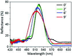
We also investigated the optical properties of the resulting 3D hierarchical nanostructures. The structural evolution of the HSCCs furthermore allows tuning the stop band of these structures, resulting in a gradual blue shift and broadening of the photonic band gap as shown in Fig. 4. The Bragg peak of the original HSCCs was located at ∼527 nm. After 9 min etching, the reflectance peak was blue-shifted to ∼515 nm and became broad simultaneously. This is caused by the lower filling factor of the dielectrics in the obtained 3D hierarchical nanostructures than in the original fcc structures. The blue shift and the broaden of the reflectance spectra are attributed to both the reduction of the filling factor of the dielectrics and the gradient morphological changes in the obtained hierarchical structures compared to the original HSCCs, which is in agreement with previous reports.41
 | ||
| Fig. 4 Reflectance spectra of the HSCCs measured from the (111) crystalline plane with various etching durations: t = 0, 2, 6 and 9 min. | ||
In conclusion, we have created complex 3D hierarchical nanostructures directly obtained from HSCCs using RIE. The proposed approach is simple and reproducible, and no mask is needed. Each layer of the resulting nanostructure has different morphologies with very fine patterns as small as ∼30 nm. This high resolution is comparable to electron-beam lithography. Different geometrical models were employed to explain the mechanism underlying the morphological changes. Both SEM images and reflectance spectra verified the morphological evolution from hollow sphere CCs to complex hierarchical structures. The fabrication of complex hierarchical 3D nanoarchitectures is of interest for potential applications such as chemical vapor sensing with high selectivity which is inspired by Morpho butterfly scales,6,42 because a gradient of surface polarity could be introduced into such a 3D hierarchical structure after a suitable surface modification, and catalysis where fine tuning the specific surface might be critical.8
Acknowledgements
K. Zhong acknowledges the support provided by the China Scholarship Council (CSC) of the Ministry of Education, P. R. China. S. Van Cleuvenbergen thanks financial support from FWO-Flanders.Notes and references
- S. Jeon, J. U. Park, R. Cirelli, S. Yang, C. E. Heitzman, P. V. Braun, P. J. A. Kenis and J. A. Rogers, Proc. Natl. Acad. Sci. U. S. A., 2004, 101, 12428–12433 CrossRef CAS PubMed.
- P. Zavala-Rivera, K. Channon, V. Nguyen, E. Sivaniah, D. Kabra, R. H. Friend, S. K. Nataraj, S. A. Al-Muhtaseb, A. Hexemer, M. E. Calvo and H. Miguez, Nat. Mater., 2012, 11, 53–57 CrossRef CAS PubMed.
- K. Ishizaki and S. Noda, Nature, 2009, 460, 367–U378 CrossRef CAS PubMed.
- Y. A. Vlasov, X. Z. Bo, J. C. Sturm and D. J. Norris, Nature, 2001, 414, 289–293 CrossRef CAS PubMed.
- T. Gorishnyy, C. K. Ullal, M. Maldovan, G. Fytas and E. L. Thomas, Phys. Rev. Lett., 2005, 94, 4 CrossRef PubMed.
- R. A. Potyrailo, R. K. Bonam, J. G. Hartley, T. A. Starkey, P. Vukusic, M. Vasudev, T. Bunning, R. R. Naik, Z. X. Tang, M. A. Palacios, M. Larsen, L. A. Le Tarte, J. C. Grande, S. Zhong and T. Deng, Nat. Commun., 2015, 6, 12 Search PubMed.
- J. Park, S. D. Wang, M. Li, C. Ahn, J. K. Hyun, D. S. Kim, D. K. Kim, J. A. Rogers, Y. G. Huang and S. Jeon, Nat. Commun., 2012, 3, 8 Search PubMed.
- R. Szamocki, S. Reculusa, S. Ravaine, P. N. Bartlett, A. Kuhn and R. Hempelmann, Angew. Chem., Int. Ed., 2006, 45, 1317–1321 CrossRef CAS PubMed.
- M. Campbell, D. N. Sharp, M. T. Harrison, R. G. Denning and A. J. Turberfield, Nature, 2000, 404, 53–56 CrossRef CAS PubMed.
- A. Isoyan, F. Jiang, Y. C. Cheng, F. Cerrina, P. Wachulak, L. Urbanski, J. Rocca, C. Menoni and M. Marconi, J. Vac. Sci. Technol., B, 2009, 27, 2931–2937 CAS.
- J. F. Galisteo-Lopez, M. Ibisate, R. Sapienza, L. S. Froufe-Perez, A. Blanco and C. Lopez, Adv. Mater., 2011, 23, 30–69 CrossRef CAS PubMed.
- Y. N. Xia, B. Gates, Y. D. Yin and Y. Lu, Adv. Mater., 2000, 12, 693–713 CrossRef CAS.
- A. vanBlaaderen, R. Ruel and P. Wiltzius, Nature, 1997, 385, 321–324 CrossRef CAS.
- L. Gonzalez-Urbina, K. Baert, B. Kolaric, J. Perez-Moreno and K. Clays, Chem. Rev., 2012, 112, 2268–2285 CrossRef CAS PubMed.
- O. Kruglova, P. J. Demeyer, K. Zhong, Y. Zhou and K. Clays, Soft Matter, 2013, 9, 9072–9087 RSC.
- T. Ding, F. Wang, K. Song, G. Q. Yang and C. H. Tung, J. Am. Chem. Soc., 2010, 132, 17340–17342 CrossRef CAS PubMed.
- G. von Freymann, S. John, V. Kitaev and G. A. Ozin, Adv. Mater., 2005, 17, 1273–1276 CrossRef CAS.
- K. P. Velikov, T. van Dillen, A. Polman and A. van Blaaderen, Appl. Phys. Lett., 2002, 81, 838–840 CrossRef CAS.
- Y. Lu, Y. D. Yin, Z. Y. Li and Y. N. Xia, Langmuir, 2002, 18, 7722–7727 CrossRef CAS.
- T. Ding, Z.-F. Liu, K. Song, K. Clays and C.-H. Tung, Langmuir, 2009, 25, 10218–10222 CrossRef CAS PubMed.
- T. Ding, Y. Long, K. Zhong, K. Song, G. Yang and C. H. Tung, J. Mater. Chem. C, 2014, 2, 4100–4111 RSC.
- J. H. Zhang, Y. F. Li, X. M. Zhang and B. Yang, Adv. Mater., 2010, 22, 4249–4269 CrossRef CAS PubMed.
- D. G. Choi, S. Kirn, E. Lee and S. M. Yang, J. Am. Chem. Soc., 2005, 127, 1636–1637 CrossRef CAS PubMed.
- D. G. Choi, H. K. Yu, S. G. Jang and S. M. Yang, J. Am. Chem. Soc., 2004, 126, 7019–7025 CrossRef CAS PubMed.
- D. G. Choi, S. G. Jang, S. Kim, E. Lee, C. S. Han and S. M. Yang, Adv. Funct. Mater., 2006, 16, 33–40 CrossRef CAS.
- S. M. Yang, S. G. Jang, D. G. Choi, S. Kim and H. K. Yu, Small, 2006, 2, 458–475 CrossRef CAS PubMed.
- T. Ding, K. Song, G. Q. Yang and C. H. Tung, Macromol. Rapid Commun., 2012, 33, 1562–1567 CrossRef CAS PubMed.
- C. H. Chang, L. Tian, W. R. Hesse, H. Gao, H. J. Choi, J. G. Kim, M. Siddiqui and G. Barbastathis, Nano Lett., 2011, 11, 2533–2537 CrossRef CAS PubMed.
- T. Y. Jeon, H. C. Jeon, S. Y. Lee, T. S. Shim, J. D. Kwon, S. G. Park and S. M. Yang, Adv. Mater., 2014, 26, 1422–1426 CrossRef CAS PubMed.
- X. A. Zhang, J. Elek and C. H. Chang, ACS Nano, 2013, 7, 6212–6218 CrossRef CAS PubMed.
- T. Ding, Y. Tian, K. Liang, K. Clays, K. Song, G. Yang and C.-H. Tung, Chem. Commun., 2011, 47, 2429–2431 RSC.
- K. Zhong, J. Li, L. Liu, W. Brullot, M. Bloemen, A. Volodin, K. Song, P. Van Dorpe, N. Verellen and K. Clays, ACS Appl. Mater. Interfaces, 2016, 10451–10458 CAS.
- Y. Chen, H. R. Chen and J. L. Shi, Acc. Chem. Res., 2014, 47, 125–137 CrossRef CAS PubMed.
- Y. Chen, Q. S. Meng, M. Y. Wu, S. G. Wang, P. F. Xu, H. R. Chen, Y. P. Li, L. X. Zhang, L. Z. Wang and J. L. Shi, J. Am. Chem. Soc., 2014, 136, 16326–16334 CrossRef CAS PubMed.
- Y. Chen, H. R. Chen, L. M. Guo, Q. J. He, F. Chen, J. Zhou, J. W. Feng and J. L. Shi, ACS Nano, 2010, 4, 529–539 CrossRef CAS PubMed.
- P. Jiang, J. F. Bertone, K. S. Hwang and V. L. Colvin, Chem. Mater., 1999, 11, 2132–2140 CrossRef CAS.
- Z. F. Liu, T. Ding, G. Zhang, K. Song, K. Clays and C. H. Tung, Langmuir, 2008, 24, 10519–10523 CrossRef CAS PubMed.
- L. V. Woodcock, Nature, 1997, 385, 141–143 CrossRef CAS.
- B. J. Y. Tan, C. H. Sow, K. Y. Lim, F. C. Cheong, G. L. Chong, A. T. S. Wee and C. K. Ong, J. Phys. Chem. B, 2004, 108, 18575–18579 CrossRef CAS.
- T. Deng, J. R. Cournoyer, J. H. Schermerhorn, J. Balch, Y. Du and M. L. Blohm, J. Am. Chem. Soc., 2008, 130, 14396–14397 CrossRef CAS PubMed.
- R. Fenollosa and F. Meseguer, Adv. Mater., 2003, 15, 1282–1285 CrossRef CAS.
- R. A. Potyrailo, T. A. Starkey, P. Vukusic, H. Ghiradella, M. Vasudev, T. Bunning, R. R. Naik, Z. X. Tang, M. Larsen, T. Deng, S. Zhong, M. Palacios, J. C. Grande, G. Zorn, G. Goddard and S. Zalubovsky, Proc. Natl. Acad. Sci. U. S. A., 2013, 110, 15567–15572 CrossRef CAS PubMed.
Footnote |
| † Electronic supplementary information (ESI) available. See DOI: 10.1039/c6nr05365c |
| This journal is © The Royal Society of Chemistry 2016 |


