Trapping, manipulation, and crystallization of live cells using magnetofluidic tweezers†
J. V. I.
Timonen
a,
C.
Raimondo
b,
D.
Pilans
c,
P. P.
Pillai
d and
B. A.
Grzybowski
*ef
aDepartment of Applied Physics, Aalto University, Espoo, Finland
bDepartment of Chemical and Biological Engineering, Northwestern University, Evanston, IL, USA
cFeinberg School of Medicine, Northwestern University, Evanston, IL, USA
dDepartment of Chemistry, Indian Institute of Science Education and Research (IISER), Pune, India
eIBS Center for Soft and Living Matter, UNIST, Ulsan, South Korea
fDepartment of Chemistry, UNIST, Ulsan, South Korea. E-mail: grzybor72@unist.ac.kr
First published on 3rd October 2016
Abstract
Live mammalian cells are captured and manipulated in magnetofluidic traps created in a suspension of biocompatible, magnetic nanoparticles by a coaxial magnetic/non-magnetic “micropen”. Upon activation by an external electromagnet, the pen creates microscale gradients of magnetic field and nanoparticle concentration that translate into directional and confining forces acting on the cells. Both individual cells and cell collections can be trapped by this method, allowing, for instance, for the formation of regularly shaped cell assemblies. The method does not entail any local heating artifacts and does not require magnetic tagging of the cells.
Conceptual insightsTechniques for single-cell manipulation are important in fundamental studies of cellular mechanics, signaling and adhesion, as well as for technologies such as in vitro fertilization. Traditional tweezing modalities can require cell tagging (e.g., with magnetic particles for magnetic tweezing), exert non-native localized mechanical stresses (microaspiration), or can cause increase in cell temperature above physiological conditions (as in optical tweezers). This work demonstrates a non-invasive, tag-free tweezing method in which cells are suspended in a magnetic liquid and are trapped and manipulated by local magnetic field gradients created with a magnetic micropen. In contrast to previous works, we can both address individual living cells and induce formation of clusters/crystals comprising multiple cells. By imposing localized gradients of magnetic field, it is also possible to vary the directionality and the strengths of the forces acting on the cells and thus study the strengths of cell–cell interactions in multicellular assemblies. Integration of this approach with confocal microscopy can provide a convenient basis for simultaneous tweezing and high-resolution imaging for cell sorting and studies of cell–cell adhesion, cellular communication, or formation of cell sheets under confining forces. |
The ability to address and manipulate individual living cells is important in modern life sciences and therapeutics, including understanding of cellular heterogeneity and its implications,1 and in techniques such as intracytoplasmic sperm injection (in vitro fertilization).2 Although various tweezing modalities have been developed, they all have their limitations. For instance, optical tweezers3,4 are known to induce heating of cells, microaspiration exposes cells to localized mechanical stress,2 and magnetic tweezing requires magnetic particles to be attached to the cell surfaces.5 Here, we describe a complimentary technique that overcomes these limitations and uses a magnetic field to trap and manipulate live cells that are not labeled with any magnetic beads. Our tweezers are based on a coaxial magnetic/non-magnetic “micropen” that creates a local magnetic field minimum in a suspension of biocompatible magnetic nanoparticles (NPs) that exert directional and confining forces on the cells. The pen is actuated by an external electromagnetic field and can engage and release the cells “on demand”. In this way, individual cells can be selected and trapped, and collections of cells can be “crystallized” into regularly shaped clusters, opening new possibilities for manipulation techniques at the level of cellular ensembles.
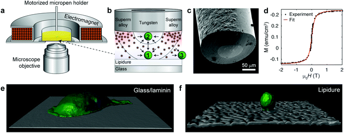
In our recent work,6 we used the coaxial micropen illustrated in Fig. 1a–c to manipulate non-magnetic colloids suspended in a paramagnetic salt solution. When magnetized by an external electromagnet (ca. 1–20 mT), the inner, non-magnetic (tungsten) portion of radius ∼50 μm created a low-field region beneath the pen's core and the outer, magnetic (supermalloy) shell of thickness ∼50–100 μm created a high-field region around the pen's perimeter. Consequently, non-magnetic objects experienced a force profile as shown in Fig. 1b and could be trapped beneath the pen's core.6 However, since the concentrated paramagnetic fluid (∼1 M Ho(NO3)3 salt) required to efficiently move colloidal particles was toxic to and incompatible with live mammalian cells, we utilized a medium that would combine high magnetic susceptibility with biocompatibility.
 | ||
| Fig. 1 Magnetofluidic tweezing of live mammalian cells. (a) Scheme of the experimental setup. The external compact electromagnet is used to magnetize the supermalloy cladding of the magnetic pen. (b) Scheme of the tip of a magnetic micropen comprising the inner, non-magnetic (tungsten) core and a magnetic (supermalloy) shell. The magnetic pen used for cell trapping has the core radius of ∼50 μm and a ∼50 μm-thick shell (note: in the trapping of colloids in ref. 6, cores down to few μm were demonstrated, but these are too small to manipulate cells). The scheme also illustrates that the magnetic nanoparticles are concentrated beneath the shell imparting more collisions directed towards the pen's inner/trapping region. Black curves indicate two trapping regions, wherein the cell is either (1) trapped when resting on a solid substrate or (2) lifted from the substrate and attracted to the micropen. Outside of the pen (3), the cell is repelled away. For more detailed discussion of force profiles, see ESI,† Section S4. (c) SEM image of the tip of a coaxial micropen fabricated as detailed in the ESI.† (d) Magnetization loop of dextran coated iron oxide nanoparticle stock dispersion measured by SQUID magnetometer. Red line is the fit to eqn (1). (e and f) Confocal reconstruction of a single MDA-MB-231 metastatic breast cancer cell on a (e) a glass slide coated with laminin (image size 141 × 141 μm2) and (f) on a non-adhesive lipidure coated glass slide (image size 210 × 210 μm2). Cell membranes were stained green (Life Technologies, CellMask Green Plasma Membrane Stain) and the nuclei blue (Life Technologies, Hoechst 33342). | ||
In this quest, we focused on suspensions of iron oxide NPs stabilized with 15–25 kDa dextran from Leuconostoc spp.7,8 In contrast to typical charge-stabilized iron oxide NPs, these sterically stabilized particles do not significantly aggregate under physiological conditions, such as in phosphate-buffered saline (PBS). In addition, they are not cytotoxic (Fig. S1, ESI† and Fig. 2–4 in the text) and in PBS medium they show only marginal internalization by cells, near or below the detection limit of ICP-AES (Inductively Coupled Plasma Atomic Emission Spectroscopy; Fig. S2, ESI†) and much less than the uptake level of citrate-coated particles. The average magnetic core diameter, d = 6.5 nm, and the concentration of the particles, n = 3.6 × 10²¹ m−3 ∼ 6 μM, were determined by measuring the magnetization loop of the synthesized stock nanoparticle dispersion (Fig. 1d; see the ESI,† for synthetic details) and fitting to the Langevin function
 | (1) |
 | ||
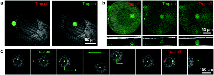
| Fig. 2 Single-cell manipulation. (a) Confocal images of a single cell under the magnetic micropen before and after turning on the external field (cell is in the trapping region “1” in Fig. 1b). (b) Confocal top- and side-views of a single cell lifted from the surface into contact with the micropen's bottom surface (cell is in the trapping region “2” in Fig. 1b). See Movie S1 (ESI†) for 3D reconstruction. (c) Trapping, moving along the surface, and releasing a single cell (Movie S2, ESI†). In (a) and (c), the green stain is for the cytoplasm (Life Technologies, calcein-AM); in (b) the green stain is for the cell membranes (Life Technologies, CellMask Green Plasma Membrane Stain); in all images blue stain is for the nucleus (Life Technologies, Hoechst 33342). | ||
 | ||
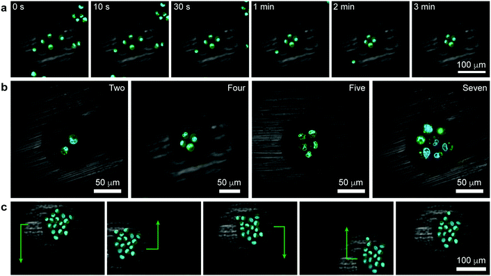
| Fig. 3 Tweezing of clusters of living cells. (a) Confocal image series illustrating the formation of a square cluster of four cells (Movie S3, see also Movie S4 for 3D reconstruction of another similar trapping experiment, ESI†). (b) Confocal images of other polygonal clusters (Movie S5, ESI†). (c) Demonstration of controlled translation of a large cell cluster (cell sheet) consisting of 16 cells (Movie S6, ESI†). Cell membranes were stained green (Life Technologies, CellMask Green Plasma Membrane Stain) and the nuclei blue (Life Technologies, Hoechst 33342). | ||
All experiments with live cells were carried out in PBS media with ∼1–3 μM nanoparticle concentration at room temperature and on a Nikon A1 inverted confocal microscope housing the magnetic pen setup (see ref. 6 for details). Cells used in the experiments discussed below were MDA-MB-231 metastatic breast cancer cells but similar results were also achieved for non-cancerous MCF-10A cells (Fig. S3, ESI†).
Based on the finite element calculations of the magnetic field (see the ESI,† Section S4), the maximum magnetic tweezing force, FM ≈ −χSμ0V∇H2/2, under typical experimental conditions was estimated to be of the order of a few tens of pN (Fig. S4, ESI†). This force is large enough to overcome gravitational force, FG = ΔρVg, which is ca. 4 pN for a spherical cell 20 μm in diameter and with a density difference with respect to the surrounding medium9 Δρ = 100 kg m−3. On the other hand, forces generated by the micropen are too small to disrupt focal adhesion contacts between the cell and substrate, which typically requires 1–100 nN.10 Accordingly, to facilitate magnetic manipulation by reducing substrate adhesion, we coated glass coverslips with ca. a 30 μm-thick layer of low-cell-adhesion lipidure.11,12 With cell-substrate contacts and adhesion largely suppressed, the cells were then nearly spherical as illustrated in Fig. 1e and f.
Fig. 2a illustrates a basic tweezing experiment of a single MDA-MB-231 cell. Initially, the pen is positioned such that the cell is beneath its supermalloy cladding. When the external electromagnetic field is turned on, the supermalloy cladding becomes magnetized. The magnetic field and the concentration of the NPs beneath this cladding become higher than either beneath the tungsten core or away from the pen. Consequently, the cell experiences a magnetic field gradient and a different frequency of collisions with the NPs from different sides and thus a net force. As illustrated in Fig. 1b (see also the ESI,† Section S4), for radial locations beneath the core and part of the shell, the force is directed inwards, towards the pen's axis of symmetry (region “1”); for radial locations closer to the pen's outer perimeter (region “3”), the force is directed radially outwards, away from the pen. The cell in Fig. 2a is in the first trapping regime and so it is moved on the lipidure surface towards the pen's axis. Interestingly, if the pen is placed closer to the cell (trapping regime “2”, Fig. 1b), the force also has a vertical component effectively lifting the cell up towards the pen's bottom surface (Fig. 2b and Movie S1, ESI†). We note that the cell is in physical contact with the tungsten core during tweezing in the trapping regime “2” (i.e., when the cell is being lifted). However, for the trapping times we tested (up to several seconds), the cell does not have time to adhere to the tungsten surface tightly, as evidenced by the fact that upon switching the field off, it is rapidly liberated from the pen. Overall, the combination of these effects allows for cell manipulation both in 2D (along the plane of the substrate) and in 3D.
One of the key features of the pen's design is that the supermalloy can be magnetized and demagnetized rapidly, on account of its very low coercivity and remanence.13 In this way, the magnetofluidic traps can be flexibly created and annihilated by, respectively, turning the external magnetic field on and off. This capability is illustrated in Fig. 2c and Movie S2 (ESI†) where the pen is first placed above a single cell, turned “on” to trap this cell, move it around, and finally release when the external electromagnet is turned “off”.
As was previously shown for colloids,6 the pen can be brought over and can subsequently – when turned “on” – trap a selective number of cells. In such a case, all the trapped cells experience an axisymmetric potential causing their tight packing around the pen's axis (Fig. 3a, Movies S3 and S4, ESI†). In effect, it is possible to form regularly shaped clusters of cells, such as triangles, squares, pentagons, or hexagons (Fig. 3b, Movie S5, ESI†). As for single cells, the trapped clusters can be moved around (Fig. 3c and Movie S6, ESI†). Such symmetric multicellular assemblies may be interesting candidates for tissue engineering or for studying cell-to-cell communication14 under well-defined geometric constraints.
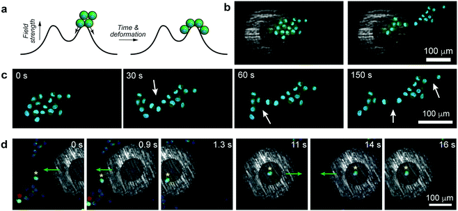
In principle, any number of cells can be selected and manipulated provided they fit within the micropen's trapping region. An interesting situation arises when the pen is positioned such that the cellular aggregate is beneath both the trapping and repulsive regions at the same time (Fig. 4a). In such a case, the aggregate elongates due to part of it being pulled towards the pen's center while the remaining part is pushed away from the pen. In effect, this magnetically induced stretching force elongates the compact cell cluster into an asymmetric sheet (Fig. 4b, c and Movie S7, ESI†), in the process causing some of the cell–cell adhesion contacts to break (in discrete steps, Fig. 4c and Movie S7, ESI†). We observe that the forces imparted by the pen (tens of pN) are commensurate with those used in previous AFM experiments to break what the authors called “small adhesion events” (ca. 45 pN in ref. 15). In making such comparisons across different experimental systems, however, it must be remembered that the strengths of the cell-to-cell contacts depend on many parameters, such as cell type, contact force or contact time – for instance, in the aforementioned ref. 15, the cells were first pressed together with 500–750 pN forces which likely resulted in their binding tighter than in our system. A potential advantage of our system over AFM-like techniques is that the cells can be first positioned very flexibly (e.g., into aggregates of desired shapes, cf.Fig. 3b) and then the forces can be applied without mechanical contact but with tunable strength (by adjusting the external magnetic field).
One more – and perhaps more technologically relevant – demonstration is shown in Fig. 4d and Movie S8 (ESI†) where the task is to selectively trap one “healthy” cell (as evidenced by green fluorescence from calcein-AM indicating intracellular esterase activity) from amongst other, nearby cells that do not show esterase activity. As the pen is turned on and approaches the cell ensemble, it initially repels all cells away from its outer perimeter (t = 0 s, cf. repulsive potential outside of the cell in Fig. 1b) but its rapid movement onto the target cell engages this particular one while keeping other cells away (t = 0.9 s and t = 1.3 s). The trapped cell can then be manipulated and moved around along arbitrary paths (t = 11 s to t = 16 s) without collecting any unwanted cells, until it can be released at a desired location.
Conclusions
In summary, we have demonstrated a system in which local magnetic-field gradients produced by a coaxial nonmagnetic/magnetic “pen” translate into magnetic forces, which ultimately allow for trapping of living mammalian cells. We expect our coaxial tweezers to be applicable to the manipulation of other living micro-organisms such as bacteria16 and microalgae,17 provided that a ferrofluid compatible with the specific micro-organism can be synthesized and that the depth of the magnetic trap can be made larger than kBT; on that note, we mention that in our previous work19 we demonstrated directed assembly of live bacteria in paramagnetic salt solutions.Our technique avoids some of the problems associated with traditional tweezing (such as heating in optical tweezers, or the need to attach magnetic particles to the cells in “direct” magnetic tweezing). We can generate forces up to tens of pN (same order of magnitude as in classical optical and magnetic tweezing), but cannot reach the level of AFM based techniques (forces up to 10 nN).18 Another downside may be the relatively large (∼μM) concentration of magnetic nanoparticles in the buffer solution that may translate into non-specific binding of these NPs to cell surfaces and alteration of cell behavior. On the other hand, ICP-AES studies in the ESI,† Section S2.2, evidence that only residual amounts of the NPs are being uptaken by or bound to cells; in addition, fluorescent labelling (e.g., for calcein-AM) indicates that the cells remain viable. Yet another practical challenge may arise if transfer of the cells to a non-magnetic medium is desired – since any magnetic confinement effects would cease upon such a change, one way around this problem would be to attach cells to the substratum (e.g., by covalent linkages, as we demonstrated previously for bacteria manipulated in paramagnetic salt solutions19), and only then exchange the medium (later, the linkages could possibly be cleaved to liberate the cells).
With these considerations, we see our technique as complementary to the existing tweezing methods. We suggest that with further improvements, this approach can be of practical interest in (i) single-cell sorting, (ii) tissue-engineering, and (iii) creation of small, regularly shaped cell ensembles in which cellular interactions (adhesion and/or transmittance of chemical signals) could be studied in quantitative detail, under controlled confinement strengths (regulated by the strength of the external electromagnet).
Acknowledgements
This work was partly supported by the Non-Equilibrium Energy Research Center (NERC), which is an Energy Frontier Research Center funded by the U.S. Department of Energy, Office of Science, Office of Basic Energy Sciences under award DE-SC0000989. J. V. I. T. was supported by a Walter Ahlström foundation postdoctoral grant. B. A. G. gratefully acknowledges the support of the Institute for Basic Science Korea, Project Code IBS-R020-D1. Research was performed on the premises of Northwestern University and ICP measurements were performed at IMSERC at Northwestern University.Notes and references
- S. Lindström and H. Andersson-Svahn, Single-Cell Analysis: Methods and Protocols, Humana Press, New York, 2012 Search PubMed.
- S. D. Fleming and R. S. King, Micromanipulation in Assisted Conception, Cambridge University Press, Cambridge, 2012 Search PubMed.
- A. Ashkin, J. M. Dziedzic and T. Yamane, Nature, 1987, 330, 769–771 CrossRef CAS PubMed.
- A. Ashkin and J. M. Dziedzic, Science, 1987, 235, 1517–1520 CAS.
- N. Bonakdar, J. Luczak, L. Lautscham, M. Czonstke, T. M. Koch, A. Mainka, T. Jungbauer, W. H. Goldmann, R. Schroder and B. Fabry, Biochem. Biophys. Res. Commun., 2012, 419, 703–707 CrossRef CAS PubMed.
- J. V. I. Timonen, A. F. Demirörs and B. A. Grzybowski, Adv. Mater., 2016, 28, 3453–3459 CrossRef CAS PubMed.
- A. Moore, R. Weissleder and A. Bogdanov, J. Magn. Reson. Imaging, 1997, 7, 1140–1145 CrossRef CAS PubMed.
- T. Shen, R. Weissleder, M. Papisov, A. Bogdanov and T. J. Brady, Magn. Reson. Med., 1993, 29, 599–604 CrossRef CAS PubMed.
- W. H. Grover, A. K. Bryan, M. Diez-Silva, S. Suresh, J. M. Higgins and S. R. Manalis, Proc. Natl. Acad. Sci. U. S. A., 2011, 108, 10992–10996 CrossRef CAS PubMed.
- B. Ladoux and A. Nicolas, Rep. Prog. Phys., 2012, 75, 116601 CrossRef PubMed.
- M. Eiraku, N. Takata, H. Ishibashi, M. Kawada, E. Sakakura, S. Okuda, K. Sekiguchi, T. Adachi and Y. Sasai, Nature, 2011, 472, 51–56 CrossRef CAS PubMed.
- K. R. Koehler, A. M. Mikosz, A. I. Molosh, D. Patel and E. Hashino, Nature, 2013, 500, 217–221 CrossRef CAS PubMed.
- W. P. Taylor, M. Schneider, H. Baltes and M. G. Allen, Transducers 97 - 1997 International Conference on Solid-State Sensors and Actuators, Digest of Technical Papers, Vol. 1 and 2, 1997, pp. 1445–1448.
- B. Alberts, A. Johnson, J. Lewis, M. Raff, K. Roberts and P. Walter, Mol. Biol. Cell, Garland Science, New York, 2007 Search PubMed.
- P. H. Puech, K. Poole, D. Knebel and D. J. Muller, Ultramicroscopy, 2006, 106, 637–644 CrossRef CAS PubMed.
- Z. M. Wang, R. G. Wu, Z. P. Wang and R. V. Ramanujan, Sci. Rep., 2016, 6, 26945 CrossRef CAS PubMed.
- A. Winkleman, K. L. Gudiksen, D. Ryan, G. M. Whitesides, D. Greenfield and M. Prentiss, Appl. Phys. Lett., 2004, 85, 2411–2413 CrossRef CAS.
- K. C. Neuman and A. Nagy, Nat. Methods, 2008, 5, 491–505 CrossRef CAS PubMed.
- A. F. Demirörs, P. P. Pillai, B. Kowalczyk and B. A. Grzybowski, Nature, 2013, 503, 99–103 CrossRef PubMed.
Footnote |
| † Electronic supplementary information (ESI) available: Experimental details, Supplementary Movies. See DOI: 10.1039/c6nh00104a |
| This journal is © The Royal Society of Chemistry 2017 |

