 Open Access Article
Wearable tactile sensor based on flexible microfluidics†
Joo Chuan
Yeo
abc,
Jiahao
Yu
b,
Zhao Ming
Koh
b,
Zhiping
Wang
a and
Chwee Teck
Lim
*bc
aSingapore Institute of Manufacturing Technology, A*STAR, 138634 Singapore
bDepartment of Biomedical Engineering, National University of Singapore, 117575 Singapore
cMechanobiology Institute, National University of Singapore, 117411 Singapore. E-mail: ctlim@nus.edu.sg
First published on 7th July 2016
Abstract
In this work, we develop a liquid-based thin film microfluidic tactile sensor of high flexibility, robustness and sensitivity. The microfluidic elastomeric structure comprises a pressure sensitive region and parallel arcs that interface with screen-printed electrodes. The microfluidic sensor is functionalized with a highly conductive metallic liquid, eutectic gallium indium (eGaIn). Microdeformation on the pressure sensor results in fluid displacement which corresponds to a change in electrical resistance. By emulating parallel electrical circuitry in our microchannel design, we reduced the overall electrical resistance of the sensor, therefore enhancing its device sensitivity. Correspondingly, we report a device workable within a range of 4 to 100 kPa and sensitivity of up to 0.05 kPa−1. We further demonstrate its robustness in withstanding >2500 repeated loading and unloading cycles. Finally, as a proof of concept, we demonstrate that the sensors may be multiplexed to detect forces at multiple regions of the hand. In particular, our sensors registered unique electronic signatures in object grasping, which could provide better assessment of finger dexterity.
Introduction
Physical sensors, such as pressure sensors and strain gauges, are fundamental elements across various industry sectors, such as healthcare,1–3 consumer electronics,4,5 robotics,6,7 and manufacturing. Among these, sensors for health monitoring are gaining popularity due to the trend of Internet of Things (IoT) which enables strong network connectivity between physical objects and their users. Therefore, these sensors are found in diverse applications, such as in fitness tracking,8,9 rehabilitation,10–12 disease monitoring,13 and wound healing.14 However, stringent demands are required for sensors to monitor human activity in their natural environment. Fundamentally, these wearable sensors should be imperceptible, non-obtrusive and yet of high reliability. Therefore, in the physical aspect, the sensors need to be flexible, bendable, lightweight and deformable to match the mechanical properties of the human skin. However, sensors relying on piezoelectric silicon-based materials fail to meet these requirements, since conventional photolithographic fabrication methods utilize rigid substrates that limit deformability.To overcome these challenges, recent research on flexible tactile or pressure sensors focuses on conductive materials using PEDOT:PSS,15 carbon nanotubes,8,16,17 metallic nanowires,4,10 novel 2D materials,18–20 or conductive fluids.21,22 Among these, conductive liquids, such as eutectic gallium indium (eGaIn) and Gallistan, present a unique proposition because they are highly conductive, non-viscous and chemically inert.23 Furthermore, they are stable over a wide range of temperatures, making them easy to implement on polymeric substrates. However, they are generally expensive due to the use of rare earth metals. Microfluidics thus presents a compelling case for the use of conductive liquids as it requires only minute amounts and physical forces are accentuated within these micro-conduits. In our previous study, we have demonstrated the use of a eGaIn-based microfluidic tactile sensor to measure localized foot pressure.24 Even so, the microchannel leads to unnecessarily high resistance which affects its pressure sensitivity.
Moreover, wearable sensors are required to be functional over a wide range of forces with high durability and sensitivity. In particular, mechanoreceptors in our fingers are able to perceive pressures as low as 4 kPa.25 Yet, our daily activities involve many activities such as keyboard typing or object grasping that covers a wide range of pressures to over 200 kPa. Furthermore, pressure changes as low as 2 kPa may be perceived by our fingers.26 Here, few pressure sensors are able to fall within the limits of both parameters. Typically, sensors showed remarkably high sensitivity only over low pressures below 10 kPa. For example, Zhu et al. developed a microstructured PDMS layer deposited with graphene to achieve 5.53 kPa−1 for pressures below 100 Pa.20 Similarly, Nie et al. developed a microdroplet array pressure sensing film of pressure sensitivity 77.7 pF kPa−1 over a range of 33 Pa to around 7 kPa.21 Other researchers have demonstrated a wider pressure range with reduced sensitivity. For example, Gerratt et al. developed an elastomeric capacitive pressure sensor that was able to measure 10 kPa to 405 kPa with a pressure sensitivity of 0.001 kPa−1.27
Here, we employed eGaIn because of its excellent electrical conductivity and physicochemical stability. We devised a microfluidic manifold comprising elastomeric rubber and polyethylene terephthalate (PET) film screen-printed with conductive electrodes. In particular, we developed microfluidic channels that are analogous to parallel electrical circuitry, thereby reducing the overall electrical resistance of the circuitry and improving its sensitivity. The sensors were attached to a customized WiFi module, allowing simultaneous data transmission at 10 Hz.
Results and discussion
Materials and methods
![[thin space (1/6-em)]](https://www.rsc.org/images/entities/char_2009.gif) :
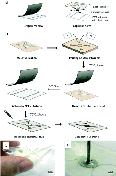
:![[thin space (1/6-em)]](https://www.rsc.org/images/entities/char_2009.gif) 1 base-to-hardener (w/w) ratio and poured directly onto the silanized wafer. It was then left at 70 °C for 1 h before it was carefully peeled off from the master mold to form the top layer of the sensor. Subsequently, the top layer of the silicone rubber and the bottom layer of the PET film were subjected to 5 min UV ozone treatment and brought together immediately. The assembly was left in the oven at 70 °C for another 2 h. The surface modification and thermal treatment resulted in an irreversible covalent bond between the two layers. Next, a liquid metallic alloy, i.e., eGaIn, was introduced into the microstructure with a needle syringe. Finally, the fluidic ports of the microstructure were sealed using a thin layer of uncured silicone rubber to produce the final working pressure sensor. Fig. 1c shows the actual fabricated sensor. Owing to the softness of the silicone elastomer (Shore Hardness 50A), a small mechanical force can lead to deformation. This resulted in displacement of the conductive fluid beyond the electrodes. Fig. 1d shows the fabricated sensor when pressed with a needle. When the force is removed, the conductive fluid returns to its original state to fill up the displaced volume.
1 base-to-hardener (w/w) ratio and poured directly onto the silanized wafer. It was then left at 70 °C for 1 h before it was carefully peeled off from the master mold to form the top layer of the sensor. Subsequently, the top layer of the silicone rubber and the bottom layer of the PET film were subjected to 5 min UV ozone treatment and brought together immediately. The assembly was left in the oven at 70 °C for another 2 h. The surface modification and thermal treatment resulted in an irreversible covalent bond between the two layers. Next, a liquid metallic alloy, i.e., eGaIn, was introduced into the microstructure with a needle syringe. Finally, the fluidic ports of the microstructure were sealed using a thin layer of uncured silicone rubber to produce the final working pressure sensor. Fig. 1c shows the actual fabricated sensor. Owing to the softness of the silicone elastomer (Shore Hardness 50A), a small mechanical force can lead to deformation. This resulted in displacement of the conductive fluid beyond the electrodes. Fig. 1d shows the fabricated sensor when pressed with a needle. When the force is removed, the conductive fluid returns to its original state to fill up the displaced volume.
Device working principle
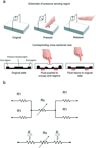
The micropatterned silicone elastomer works similar to a micropump system, as illustrated in Fig. 2a. In particular, when the load is applied to the pressure sensing region, the microchannel collapses under the force, causing the fluid to be displaced to the end regions. Due to the change in cross-sectional area, the overall resistance of the pressure sensor is increased. The electrical resistance may be expressed in correlation with the silicone elastomer resembling mechanical beam acting on the conductive fluid. Assuming a uniform pressure P acting on the circular surface, the normalized electrical resistance, ΔR/R0, of the pressure sensor can be simplified by eqn (1), | (1) |
Characterization of pressure sensor
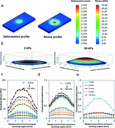
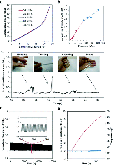
To assess the sensitivity of the pressure sensor, we simulated localized loads between 2 kPa and 100 kPa over the entire pressure sensing region (i.e. contact diameter of 5 mm). As illustrated in Fig. 3a, the pressure is mainly confined within the pressure sensing region due to the material properties of the elastomer being soft and easily compressible. Fig. 3b further describes the deformation profile of the silicone elastomer in three dimensions, assuming a material thickness of 2 mm. When we compared the deformation profile due to the pressure load between 2 kPa and 50 kPa, we observed significant deformation with increasing pressure. Fig. 3c further quantifies the stress profile of the silicone elastomer over a range of loads from 2 kPa to 100 kPa (i.e. 2, 10, 15, 25, 50, 65, 75, 100 kPa). As shown, the stress region is the highest at the center of the pressure sensing region and decreases away from its axis. Furthermore, the stress increases proportionately with increasing pressure. Similarly, we also observed the deformation profile of the pressure sensing region over the same simulated loads. In Fig. 3d, the deformation profile of the micropatterned silicone elastomer is described quantitatively over the same applied loads. Notably, even a small pressure of 2 kPa translates to relatively large deformation of over 20 μm. Therefore, it indicates that our flexible pressure sensor possesses high localized sensitivity. Furthermore, when the simulated localized loads increase beyond 50 kPa, we observed nonlinear mechanical deformations due to the viscoelastic nature of the material. Finally, we simulated the effects of a localized pressure of 10 kPa over a range of thicknesses of the pressure sensor (i.e. 1, 2, 3, 5, 10 mm). Fig. 3e shows the deformation profile across the cross section of the pressure sensing region. With increasing thickness, the material is stiffer and subject to poorer deformations. Therefore, the pressure range and sensitivity can be altered based on the sensor thickness for different applications.Next, we characterized the pressure sensing performance of the flexible pressure sensor using a universal loading machine. Static loads were performed under compressive ramp-hold-release load cycles on the device, starting from a pressure of 25.4 kPa up to 76.4 kPa. Fig. 4a shows the stress–strain curve of the silicone elastomer under the applied pressures. Based on this characterization, we determined the material properties of the silicone elastomer. Particularly, we noted that pressure within 48 kPa exhibited a fairly linear stress–strain relation with a low compressive modulus of 209 kPa. Evidently, a force as small as 18 kPa can result in a compressive strain of approximately 10%, highlighting its sensitivity. Furthermore, we also observed that at incremental pressure above 50 kPa, the pressure sensor exhibited its viscoelastic property. At this stage, the polymer were tightly compressed and therefore responded with a stiffer modulus of approximately 1 MPa. Overall, the deformation is well sufficient to be translated in the microfluidic structures. We further characterized the electrical resistance using a wide range of loads from 4 kPa up to 100 kPa to determine its range, linearity and sensitivity. Fig. 4b further presents the normalized electrical resistance with respect to its pressure. Similarly, we noted a linear relationship up to 50 kPa, with an R-squared linear fitting value of 0.993. Pressure sensitivity may be defined by the normalized resistance per unit pressure, thus the sensor sensitivity may be measured from the slope function, approximating to 0.05 kPa−1. This is a few orders more sensitive than other reported sensors of similar working pressure range,27–29 and approximately 25 times higher than that of our previous study.24 Furthermore, we noted that as the pressure increased above 50 kPa, the normalized resistance increased less than proportionately. Again, this correlated well with the viscoelastic effect described earlier. Due to the stiffer modulus at higher compressive load, the rate of deformation was reduced, resulting in less than proportionate increase in electrical resistance. Even so, the pressure followed a linear correlation of 0.928 and the pressure sensitivity within this range was up to 0.024 kPa−1, which is well sufficient for distinguishing bodily interactions.
The robustness of liquid-based sensors has been previously demonstrated,19,30 and they were functional even when rolled over by a car wheel.24 To further validate our sensor, we subjected the sensor to extreme deformations, such as bending, twisting, and crushing. Fig. 4c shows the sensor under these deformations. We noted that the sensor remains intact and functional with stable electrical connectivity even after these deformations. To determine its reliability, we performed dynamic load on the microfluidic pressure sensor using a linear actuator. We subjected the sensor to cyclic loads of over 2500 cycles. Fig. 4d presents the dynamic profile of the normalized resistance of the sensor during the cyclic loads, and the inset shows the electrical profile of the sensor across a representative time scale of 200 seconds. Here, the profile was clearly consistent and highly repeatable. However, over an extended period of cyclic loading, the peak resistance decreased slightly less than 8%. This could be due to the elastic strain energy of the elastomer, which resulted in stress relaxation with cyclic loading. Despite the repeated loading, the integrity of the sensor was highly preserved, further highlighting its durability and robustness. Next, we subjected our sensor to temperature variations between 15 °C and 45 °C to observe for changes in its electrical profile. First, we cooled the sensor using ice packs. Subsequently, the sensor was mounted on an electric heater. Both the temperature and the electrical resistance of the sensor were monitored continuously. Fig. 4e shows the resistance profile of the sensor with its corresponding temperature. Evidently, the device was not affected by temperature variations. Overall, our pressure sensor is capable of measuring the force consistently over a wide range of pressures and continuously over long periods. It also remained reliable over a wide range of temperatures.
Application of pressure sensor
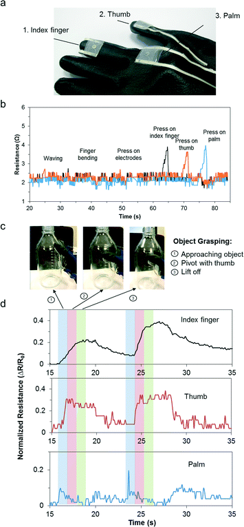
Object grasping is an essential task in human daily activity primarily involving the palm, index finger and thumb. The contact forces have to be sufficiently large to prevent slipping but not excessive to cause damage to the object.31 Typically, object manipulation requires contact pressures between 2 N and 10 N.32 This is equivalent to approximately 5 kPa to 50 kPa. As a proof-of-concept, three sensors were embedded at the following locations on the glove: distal phalange of the right index finger, right anterior trapezoid of the palm, distal phalange of the right thumb (see Fig. 5a). The sensors were located on relatively flat regions on the hand to minimize deformation induced changes due to movement or bending. We further validated this by performing hand movements, such as waving, finger bending, and pressing on the electrodes with negligible resistance changes observed. To ensure independent pressure sensor readouts, we pressed on the individual sensors sequentially and observed distinct peaks (Fig. 5b). The subject then performed object grasping and the dynamic pressure responses were monitored simultaneously. Fig. 5c presents the actions that corresponded to object grasping actions, namely “approaching the object”, “pivot with thumb”, and “lift off”. As shown in Fig. 5d, the hand approached the object until the palm came into contact with the device. Subsequently, the thumb flexed to form a pivot around the object. Finally, the index finger flexed fully and provided the highest grip force before the object was successfully lifted off the table. The electrical resistance readouts were consistent and repeatable. This highlights its potential as a wearable pressure sensor for real-time monitoring and analysis. In particular, a simple object grasping task may be analyzed based on the contributions from major coordinating muscle groups and could potentially be used as a rehabilitative or diagnostic medical screening tool.Conclusions
We developed a facile method of integrating a micropatterned silicone elastomer filled with conductive fluid and bonded to a polymeric film to form a microfluidic tactile or pressure sensor with high flexibility, durability, and sensitivity. The flexible pressure sensor has sensitivity of 0.05 kPa−1 and is capable of distinguishing mechanical loads of between 4 kPa and 100 kPa. Furthermore, the microfluidic pressure sensor is capable of withstanding repeated loading without compromising its integrity. We believe this sensor will have great potential for use as a microfluidic wearable technology for biomedical and healthcare applications.Acknowledgements
This research was supported by the National Research Foundation, Prime Minister's Office, Singapore under its medium-sized centre programme, Centre for Advanced 2D Materials and its Research Centre of Excellence, Mechanobiology Institute, as well as the MechanoBioEngineering Laboratory at the Department of Biomedical Engineering of the National University of Singapore. J. C. Y. acknowledges the support from Agency of Science, Technology and Research (A*STAR) Singapore for his graduate scholarship.Notes and references
- S. L. Swisher, M. C. Lin, A. Liao, E. J. Leeflang, Y. Khan, F. J. Pavinatto, K. Mann, A. Naujokas, D. Young, S. Roy, M. R. Harrison, A. C. Arias, V. Subramanian and M. M. Maharbiz, Nat. Commun., 2015, 6, 6575 CrossRef PubMed
.
-
M. Chattopadhyay and D. Chakraborty, in Next Generation Sensors and Systems, ed. C. S. Mukhopadhyay, Springer International Publishing, Cham, 2016, pp. 143–160, DOI:10.1007/978-3-319-21671-3_7
.
- M. Melnykowycz, M. Tschudin and F. Clemens, Sensors, 2016, 16, 326 CrossRef PubMed
.
- S. Gong, W. Schwalb, Y. Wang, Y. Chen, Y. Tang, J. Si, B. Shirinzadeh and W. Cheng, Nat. Commun., 2014, 5, 3132 Search PubMed
.
- S. Xu, Y. Zhang, L. Jia, K. E. Mathewson, K.-I. Jang, J. Kim, H. Fu, X. Huang, P. Chava, R. Wang, S. Bhole, L. Wang, Y. J. Na, Y. Guan, M. Flavin, Z. Han, Y. Huang and J. A. Rogers, Science, 2014, 344, 70–74 CrossRef CAS PubMed
.
- R. F. Shepherd, F. Ilievski, W. Choi, S. A. Morin, A. A. Stokes, A. D. Mazzeo, X. Chen, M. Wang and G. M. Whitesides, Proc. Natl. Acad. Sci. U. S. A., 2011, 108, 20400–20403 CrossRef CAS PubMed
.
- S. A. Morin, R. F. Shepherd, S. W. Kwok, A. A. Stokes, A. Nemiroski and G. M. Whitesides, Science, 2012, 337, 828–832 CrossRef CAS PubMed
.
- C. Yeom, K. Chen, D. Kiriya, Z. Yu, G. Cho and A. Javey, Adv. Mater., 2015, 27, 1561–1566 CrossRef CAS PubMed
.
- Y. Menguc, Y. L. Park, H. Pei, D. Vogt, P. M. Aubin, E. Winchell, L. Fluke, L. Stirling, R. J. Wood and C. J. Walsh, Int. J. Robot. Res., 2014, 33, 1748–1764 CrossRef
.
- Y. Joo, J. Byun, N. Seong, J. Ha, H. Kim, S. Kim, T. Kim, H. Im, D. Kim and Y. Hong, Nanoscale, 2015, 7, 6208–6215 RSC
.
- E. Sardini, M. Serpelloni and V. Pasqui, IEEE Trans. Instrum. Meas., 2015, 64, 439–448 CrossRef
.
- Y. L. Park, B. R. Chen, N. O. Perez-Arancibia, D. Young, L. Stirling, R. J. Wood, E. C. Goldfield and R. Nagpal, Bioinspiration Biomimetics, 2014, 9, 016007 CrossRef PubMed
.
- C. M. Boutry, A. Nguyen, Q. O. Lawal, A. Chortos, S. Rondeau-Gagné and Z. Bao, Adv. Mater., 2015, 27, 6954–6961 CrossRef CAS PubMed
.
- Y. Hattori, L. Falgout, W. Lee, S.-Y. Jung, E. Poon, J. W. Lee, I. Na, A. Geisler, D. Sadhwani, Y. Zhang, Y. Su, X. Wang, Z. Liu, J. Xia, H. Cheng, R. C. Webb, A. P. Bonifas, P. Won, J.-W. Jeong, K.-I. Jang, Y. M. Song, B. Nardone, M. Nodzenski, J. A. Fan, Y. Huang, D. P. West, A. S. Paller, M. Alam, W.-H. Yeo and J. A. Rogers, Adv. Healthcare Mater., 2014, 3, 1597–1607 CrossRef CAS PubMed
.
- J. Zhang, M. Shi, H. Chen, M. Han, Y. Song, X. Cheng and H. Zhang, IEEE 29th International Conference on Micro Electro Mechanical Systems (MEMS), 2016, pp. 173–176 Search PubMed.
- S. Khan, S. Tinku, L. Lorenzelli and R. S. Dahiya, IEEE Sens. J., 2015, 15, 3146–3155 CrossRef CAS
.
- M. Amjadi, Y. J. Yoon and I. Park, Nanotechnology, 2015, 26, 375501 CrossRef PubMed
.
- H. Tian, Y. Shu, X.-F. Wang, M. A. Mohammad, Z. Bie, Q.-Y. Xie, C. Li, W.-T. Mi, Y. Yang and T.-L. Ren, Sci. Rep., 2015, 5, 8603 CrossRef CAS PubMed
.
- Kenry, J. C. Yeo, J. Yu, M. Shang, K. P. Loh and C. T. Lim, Small, 2016, 12, 1593–1604 CrossRef CAS PubMed
.
- B. Zhu, Z. Niu, H. Wang, W. R. Leow, H. Wang, Y. Li, L. Zheng, J. Wei, F. Huo and X. Chen, Small, 2014, 10, 3625–3631 CrossRef CAS PubMed
.
- B. Nie, R. Li, J. D. Brandt and T. Pan, Lab Chip, 2014, 14, 1107–1116 RSC
.
- Y. L. Park, B. R. Chen and R. J. Wood, IEEE Sens. J., 2012, 12, 2711–2718 CrossRef CAS
.
- M. D. Dickey, R. C. Chiechi, R. J. Larsen, E. A. Weiss, D. A. Weitz and G. M. Whitesides, Adv. Funct. Mater., 2008, 18, 1097–1104 CrossRef CAS
.
- J. C. Yeo, Kenry, J. Yu, K. P. Loh, Z. Wang and C. T. Lim, ACS Sens., 2016, 1, 543–551 CrossRef CAS
.
- A. Kaneko, N. Asai and T. Kanda, J. Hand Ther., 2005, 18, 421–425 CrossRef PubMed
.
- H. E. Wheat, L. M. Salo and A. W. Goodwin, J. Neurosci., 2004, 24, 3394–3401 CrossRef CAS PubMed
.
- A. P. Gerratt, H. O. Michaud and S. P. Lacour, Adv. Funct. Mater., 2015, 25, 2287–2295 CrossRef CAS
.
- H.-B. Yao, J. Ge, C.-F. Wang, X. Wang, W. Hu, Z.-J. Zheng, Y. Ni and S.-H. Yu, Adv. Mater., 2013, 25, 6692–6698 CrossRef CAS PubMed
.
- A. D. Smith, F. Niklaus, A. Paussa, S. Vaziri, A. C. Fischer, M. Sterner, F. Forsberg, A. Delin, D. Esseni, P. Palestri, M. Östling and M. C. Lemme, Nano Lett., 2013, 13, 3237–3242 CrossRef CAS PubMed
.
- H. Ota, K. Chen, Y. Lin, D. Kiriya, H. Shiraki, Z. Yu, T. J. Ha and A. Javey, Nat. Commun., 2014, 5, 5032 CrossRef CAS PubMed
.
- V. Iyengar, M. J. Santos, M. Ko and A. S. Aruin, Neurorehabil. Neural Repair, 2009, 23, 855–861 CrossRef PubMed
.
- D. A. Nowak, J. Hermsdörfer and H. Topka, J. Neurol., 2003, 250, 850–860 CrossRef PubMed
.
Footnote |
| † Electronic supplementary information (ESI) available: Calculation of deformation mechanics. See DOI: 10.1039/c6lc00579a |
| This journal is © The Royal Society of Chemistry 2016 |

