 Open Access Article
Nano-liter droplet libraries from a pipette: step emulsificator that stabilizes droplet volume against variation in flow rate†
Filip
Dutka
ab,
Adam S.
Opalski
a and
Piotr
Garstecki
*a
aInstitute of Physical Chemistry, Polish Academy of Sciences, Warsaw, Poland. E-mail: garst@ichf.edu.pl
bInstitute of Theoretical Physics, Faculty of Physics, University of Warsaw, Warsaw, Poland
First published on 29th April 2016
Abstract
Many modern analytical assays, for example, droplet digital PCR, or screening of the properties of single cells or single mutated genes require splitting a liquid sample into a number of small (typically ca. nano-liter in volume) independent compartments or droplets. This calls for a method that would allow splitting small (microliter) samples of liquid into libraries of nano-liter droplets without any dead volume or waste. Step emulsification allows for facile protocols that require delivery of only the sample liquid, yet they typically exhibit dependence of the droplet size on the rate at which the sample is injected. Here, we report a novel microfluidic junction that reduces the dependence of the volume of droplets on the rate of injection. We also demonstrate generation of tightly monodisperse nanoliter droplets by introduction of solely the dispersed phase into the system from an automatic pipette. The method presented here can readily be used and can replace the sophisticated devices typically used to generate libraries of nano-liter droplets from liquid samples.
Introduction
Splitting of a liquid sample into multiple isolated compartments of known and tightly controlled volume is a key step in many traditional and new analytical schemes. Collections (or ‘libraries’) of droplets containing small portions of the sample find use in screening of e.g. i) random libraries of mutations of DNA,1–3 ii) mutated microorganisms and enzymes4–6 and iii) digital analytical schemes – predominantly digital PCR,7 but also other (e.g. immuno-8–10) digital assays. These techniques would greatly benefit from a readily available and easy-to-use method for splitting of a small liquid sample (i.e. microliter volumes) into nanoliter droplets, without any dead volume or waste associated with the process. Ideally, such a method should allow the generation of droplets in a process as simple as e.g. pipetting the liquid sample into a container.In microfluidics, droplets can be generated in many different ways, yet almost all of them require fairly sophisticated experimental setups (e.g. syringe pumps and precise control of the flow rates).11–13 These techniques are also typically characterized by significant dead volumes making it virtually impossible to simply split a few microliters of the liquid sample into droplets.
Step emulsification is a process governed by capillary forces for small velocities of the dispersed phase.14,15 A dispersed droplet phase flows in a microchannel filled with the continuous phase onto a sharp edge (a ‘step’) followed by an abrupt widening of the channel. When a stream (or a large plug) of the droplet phase reaches the step, small droplets form, of a size closely related to the geometrical features of the step. The droplet formed at the step grows until it reaches a critical size. Then the curvature of the interface upstream of the step (in a ‘neck’) is larger than the curvature in the growing ‘head’ of the droplet and the droplet spontaneously breaks off (see e.g. Dangla et al.16,17 or Li et al.18 for an elegant explanation and a model of the process).
From the practical point of view, step emulsification techniques can be divided into two classes. In the first scheme, both the continuous and the droplet liquids are actively injected into the system. In the second scheme, only the droplet phase is injected. In the two-phase injection process, capillary focusing can be used to reduce the size (cross-section) of the stream of the droplet liquid before it breaks at the step.18–22 With this technique, it is possible to generate droplets as small as femto- and attoliter in volume.23 However, simultaneous injection of two liquids is not compatible with the simplest experimental protocol – of e.g. injecting a liquid from an automatic pipette. It would be highly preferable that only the droplet liquid is actively injected, and preferentially in a manner as simple and crude as possible. Below, we discuss only the one-phase injection step emulsification process.
In the systems designed for emulsification upon injection of solely the droplet liquid, the space of parameters that govern the process is limited to 1) the geometry of the emulsification junction and 2) the rate of inflow of the liquid. Further, as we wish to effectively immunize the dynamics against variation in the rate of flow of the liquid, the ‘design space’ is limited to just the geometry of the junction.
In quasi-static processes, the curvature of the interface is proportional to the pressure difference inside the droplet and in the continuous phases. As the droplet phase flows into the outlet chamber, its tip expands. The curvature of the plug-continuous phase interface decreases as the droplet grows, lowering the pressure inside the tip. At one point, the droplet phase left in the inlet channel detaches from the walls of the microchannel and forms a neck.16,17 The liquid is no longer confined and Plateau–Rayleigh instability forces the break-up and formation of a droplet. The newly formed droplet detaches from the plug and flows into the outlet chamber. Upon detachment, the liquid pressures inside the droplet and in the thread left in the inlet channel are the same, and so are the Laplace pressures. Thus, the radius of such a formed droplet equals the width of the inlet channel.17
At small values of the capillary number Ca = μv/γ ≪ 1 (μ is the viscosity of the continuous phase, v is the velocity of the droplet phase, and γ is the interfacial tension), capillary pressure dominates over viscous stresses. The critical capillary number Cacr marks the transition from the dominance of the capillary forces over the viscous ones. For a fixed composition of the liquids, the only factor that can change is the velocity of the dispersed phase. It imposes the existence of the critical velocity of the droplet phase, over which the droplets will be generated in a different regime. For velocities above a critical velocity, vcr, the droplet size increases more rapidly with the speed of flow.24,25
Kobayashi et al.26 showed that the aspect ratio AR (width/height) of the microchannel influences the size distribution of the droplets. They prepared a silicon plate with a matrix of 10![[thin space (1/6-em)]](https://www.rsc.org/images/entities/char_2009.gif) 000 straight-through microchannels 200 μm in length and set 100 μm apart from each other. Three sizes were tested, 25.2 × 13.3, 32.8 × 12 and 40.8 × 10.8 μm, with ARs equal to 1.9, 2.7 and 3.8, respectively. The outlet chamber was common for all channels with the continuous phase flowing perpendicularly to the inlet channels. For a constant, fixed rate of flow only for width-to-height aspect ratios ARs of >3, highly monodisperse droplets were obtained, characterized by a coefficient of variation (CV) of the diameter below 2%. The influence of different flow rates of the dispersed phase was not investigated.
000 straight-through microchannels 200 μm in length and set 100 μm apart from each other. Three sizes were tested, 25.2 × 13.3, 32.8 × 12 and 40.8 × 10.8 μm, with ARs equal to 1.9, 2.7 and 3.8, respectively. The outlet chamber was common for all channels with the continuous phase flowing perpendicularly to the inlet channels. For a constant, fixed rate of flow only for width-to-height aspect ratios ARs of >3, highly monodisperse droplets were obtained, characterized by a coefficient of variation (CV) of the diameter below 2%. The influence of different flow rates of the dispersed phase was not investigated.
In order to obtain highly monodisperse droplets, instead of tuning the aspect ratio, one can add a terrace downstream of the microchannel. It unlocks the geometrical confinement in one, say horizontal, direction (perpendicular to flow).24,27–29 Terraces have finite length, downstream of which the confinement is lifted also in the second perpendicular to flow direction. With the terraces, one can obtain highly monodisperse droplets flowing out of 10![[thin space (1/6-em)]](https://www.rsc.org/images/entities/char_2009.gif) 000 parallel slots, with a CV of the diameter below 5% for the capillary number smaller than the critical capillary number Cacr.24 When Ca exceeds Cacr, the droplet diameters significantly increase with higher velocity of the dispersed phase.
000 parallel slots, with a CV of the diameter below 5% for the capillary number smaller than the critical capillary number Cacr.24 When Ca exceeds Cacr, the droplet diameters significantly increase with higher velocity of the dispersed phase.
In all of the referenced systems, the volume of the droplets depends on the rate of inflow of the droplet phase. Sugiura et al.24 used Cacr values (and subsequently the critical velocity of the droplet phase, vcr) to relate the flow rate and droplet diameter. The value of Cacr ∼ 0.05 marked the rate of flow at which the droplet diameter started increasing significantly with the flow rate. Dangla et al.16 reported a similar observation, presenting that for very low flow rates from 0.003 ml h−1 to 0.06 ml h−1 (and consequently, very low Ca and throughput), the droplet size is not sensitive to the fluctuations of the flow.
The dependence of droplet volume on the flow rate stems from two effects. First, the process of break-up requires a finite time, during which the droplet is continuously filled up with the inflowing liquid, leading to a dependence of the volume of the droplet on the rate of inflow of the liquid. Second, the rate of flow of the droplet phase affects the process of break-up, amplifying the first effect. As a result, the volume of the droplets increases together with the increase in the rate of flow of the sample.
The geometry of the microfluidic junction is the key factor in the functional performance of step emulsificator devices. A recent study by Amstad et al.30 showed that an improved geometry of the terrace may increase the range of rates of flow that allow the formation of droplets of a fixed size. Here, we demonstrate that an appropriate design of the passive structures that guide the position of break-up and the delivery of the continuous liquid to that position may improve the stability of the droplet size. The devices that we report here offer generation of monodisperse emulsions in a process robust against fluctuations in the rate of delivery of the liquid. This, in turn, allows for using portable equipment e.g. electronic pipettes for generation of libraries of nanoliter droplets from microliter liquid samples.
Below, we first compare our designs with a straight-through microchannel without any modifications. Then, we present the dependence of the liquid viscosities on droplet sizes. As the design is scalable, we demonstrate generation of both nanoliter and subnanoliter droplets. A special design of the orifice comprising a constriction in the inlet channel and bypasses enables droplet generation with syringe pumps as well as electronic pipettes with CVs of volume below 5% and of the diameters below 1.7%.
Results
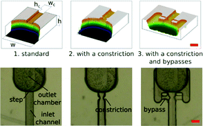
Typically, in a standard geometry of microfluidic chips for step emulsification, the inlet channel is rectangular, and the droplets formed at the step are transported from the step by perpendicular flow. In our setup, the systems are prefilled with an oil phase, and only the water phase is injected into the system. Channels are aligned along the gravitational field, so the droplets are transported from the step by buoyancy, alleviating the potential problem of clustering of droplets around the step (ESI†).We present the results of experiments conducted on three different geometries of the junctions: (1) standard step emulsification geometry, (2) geometry with a constriction within the inlet channel near the step and (3) geometry with a constriction and with bypasses within the inlet channel near the step (see Fig. 1). Bypasses have been reported previously as a tool for hard-wired operations on droplets.31 In all these geometries, the inlet channels are quadratic in cross-section with width and height wc = hc = 200 μm, and the outlet chamber is significantly bigger, w = h = 1 mm.
In a standard step emulsification device, the position at which the stream of the droplet phase breaks depends on the rate of flow of the liquid. The higher the volumetric flow rate of the droplet phase, the lower downstream the neck forms.17 As a result, the higher the rate of inflow of the liquid, the higher the volume of the droplets. The shape of the neck formed by the stream of the droplet phase before detachment is the same (or similar) for different flow rates, and only its position along the inlet channel varies with the rate of flow.
In order to reduce the influence of the volumetric flow rate on the droplet sizes, and on the location of the neck, we introduced a constriction in the inlet channel. The width of the channel in the constriction equals half of the nominal channel width. The length (along the flow) of the constricted region is also zc = 100 μm. The constriction design is aimed at localizing the instability, i.e. the location of ‘necking’. We checked experimentally that indeed the stream of the droplet phase always breaks up at the same point in the systems with the constriction, while the location of the neck (and break-up) in standard step emulsification geometry gradually progressed downstream with increasing rate of flow (see Fig. S3 in the ESI†).
In order to find the position of the constriction which renders the smallest droplet sizes, we performed experiments using microfluidic chips with different locations of the constriction along the main channel (ESI,† Fig. S2). We found that the distance of Δz = 100 μm upstream from the edge of the step provides the lowest dependence of the volume of droplets on the rate of flow of the droplet phase.
In the third geometry, apart from the constriction that localizes the instability, we also added shallow bypasses that passively allow for the supply of the continuous liquid to the location of break-up. The role of the bypasses is to 1) further stabilize the location of the instability and 2) to increase the speed of break-up of the neck once it crossed the stability criterion.17 As the neck breaks, without the bypasses, the continuous liquid must travel to the neck along the thin films between the walls of the channel and the liquid–liquid interface. This slows down the necking and may allow for movement of the neck along the channel. The bypasses are narrow (their width is equal to half the width of the main channel, wb = 100 μm) and shallow (the height is four times smaller than the height of the main channel, hb = 50 μm). Their geometry allows for the flow of oil from the outlet chamber to the neck. At the same time, the narrow lumen does not allow for the droplet phase to enter the bypass. We observed that addition of the bypasses resulted in further decrease of the volumes of droplets (Fig. 2).
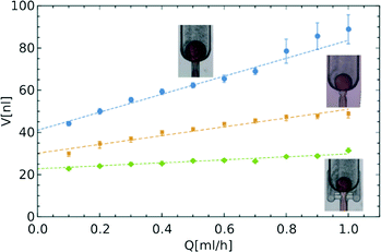 | ||
Fig. 2 Comparison of droplet sizes for the three different designs. Linear dependence V = V0(1 + αQ/Q0) is fitted to experimental data with:  V0 = 41.0 nl, α = 7.9; V0 = 41.0 nl, α = 7.9;  V0 = 30.2 nl, α = 5.2; V0 = 30.2 nl, α = 5.2;  V0 = 22.8 nl, α = 2.4, where Q0 = 7.6 ml h−1 is the characteristic flow rate for water droplets in HFE 7500 oil (ESI†). V0 = 22.8 nl, α = 2.4, where Q0 = 7.6 ml h−1 is the characteristic flow rate for water droplets in HFE 7500 oil (ESI†). | ||
For high volumetric flow rates, droplets are not able to flow from the step before the next droplet comes, so they collide and coalesce. Adding a surfactant to the droplet phase to prevent coalescence does not resolve this problem, and the droplets still collide and sometimes coalesce. As we work with a fluorinated continuous phase that is most commonly used in biochemical and biological droplet assays, we used a vertical alignment of the chip. Water is less dense than oils and the buoyancy speeds up the flow of droplets away from the step, while bypasses reduce clogging and enable droplet formation at higher volumetric rates of flow.
In order to quantitatively compare the stability of droplet size against variation of the rate of flow in different designs, we introduced a measure of change in volume in relation to the change in the flow rate – the coefficient α. This dimensionless parameter allows us to define the size of a formed droplet (V) by a relation between the characteristic volume (V0), for a quasi-static process (in the limit of low flow rate Q of the droplet phase), and in terms of the change in the flow rate (Q/Q0), where the choice of Q0 depends on the densities and viscosities of both phases (more details in the ESI†)
| V = V0(1 + αQ/Q0). | (1) |
The dimensionless parameter α allows us to compare the dependence of the volume of droplets on the rate of flow between different systems. The larger the coefficient α, the faster the increase in the volume of droplets with increasing flow rate. In an ideal system, α should be equal to zero and the volume of the droplet would be fixed at V0 regardless of the rate of flow. By calculating the values of the coefficient α for the data presented in Fig. 2, we see that the introduction of the constriction (α = 5.2) and bypasses (α = 2.4) significantly reduce the dependence of the volume of droplets on the rate of inflow of the droplet phase, as compared to the unmodified step emulsificator (α = 7.9). The factor α is a versatile tool enabling a comparison of different systems, including those that are state-of-the-art, as presented in Table 1.
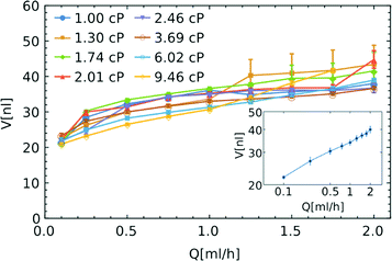
An ideal system for generation of libraries of nanoliter droplets from microliter samples should allow the execution of the procedure largely independent of the viscosity of the sample. In order to check the influence of viscosity of the droplet phase on the formation of droplets, we used several solutions of glycerin in water (with viscosities η varied between 1 and 9.46 cP).32 We compared the size of the droplets containing these solutions of different viscosities with those generated from neat water. We did not observe any significant relationship between the viscosity of the droplet phase and the volume of the generated droplets (see Fig. 3). For the flow of the droplet phase over 1 ml h−1, the change of viscosity between 1 and 9.5 cP does not produce any systematic change in the volume of the droplets. We still observe the dependence of the volume on the rate of flow – the higher the flow rate, the larger the droplets (see Fig. 3).
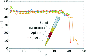
Our step emulsification system is designed to generate droplets upon supply of only the droplet phase. In order to check this functionality, and that indeed the volumes of the droplets are not sensitive to the instantaneous rate of flow, we performed model experiments with a pipette as the source of flow in the system with a neck and bypasses as in Fig. 1. We used an electronic pipette. For both drawing the plug and pipetting, we used the minimum available rate of flow Qmin = 1.584 ml h−1. The pipette was directed downwards during droplet formation – the channel was U-turn-shaped, so the droplets flowed upwards from the step and did not clog. The flow rate generated by the pipette was not attained instantaneously so we prepared a sample with plugs (see Fig. 4): 1.5 μl of oil, 2 μl of air, 4 μl of sample and at the end 5 μl of oil. An air plug is necessary to prevent droplet break-up before reaching the step by the droplet phase, and the formation of small satellite droplets. The oil plug at the end pushes the whole droplet phase through the step.
We performed four experiments of generation of a library of droplets from a 4 μl sample of water. Except for the last five droplets, the coefficient of variation of volume was below 5% (corresponding to a CV of the diameter less than 1.7%), as can be seen in Fig. 4. The difference in the volumes of those droplets is due to the fact that the liquid pressure in the short thread in the inlet channel is higher than that in the long threads. The pressure inside the detached droplets is thus higher, so the radius is smaller.
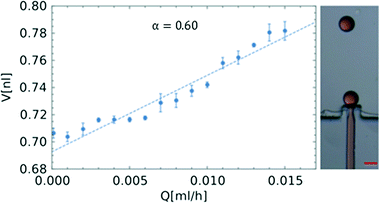
The size of the droplets scales proportionally with the dimensions of the inlet channel.16,17 In order to form nanoliter droplets, we fabricated a microfluidic chip employing PDMS on a master prepared using a lithographic process, with the step geometry with constriction and bypasses and quadratic in cross-section having an inlet channel width of wa = 62.7 μm. The geometry of the system is the same as that in a larger PC device with a neck and bypasses (Fig. 1 and S2 in the ESI†). As was discussed before for quasi-static droplet formation for the system without a neck and bypasses, the radius of the formed droplets should equal the width of the inlet channel. In this case, the volumes of the droplets would equal one nanoliter. We obtained smaller droplets in our system (Fig. 5).
Materials and methods
The microfluidic chips comprise quadratic cross-section straight inlet channels and an outlet chamber of much larger width than that of the inlet channels. The chips were fabricated by using standard microfabrication techniques used for prototyping: in polycarbonate by CNC milling33 and in glass–PDMS34,35 by soft lithography. The devices were then inspected with a Bruker ContourGT-K optical profilometer (Bruker, USA) to ensure that all devices used are of the same size and quality. We modified the surface of the channels with Aculon E coating (Aculon, Inc., USA) by filling and drying the channels three times. More details can be found in the ESI.†The continuous phase consisted of either FC40 oil (3M, USA) with addition of 0.5% w/w surfactant perfluorooctanol (Sigma-Aldrich, Germany) or HFE 7500 oil (3M, USA) with addition of 0.25% surfactant PFPE–PEG–PFPE (Z.D. Chemipan, Poland). The droplet phase consisted of either 1) distilled water with Congo Red for better contrast or 2) a solution of glycerin (POCH, Poland) with Milli-Q water and Congo Red.
To fill the system with the continuous phase and inject the droplet phase into the system, we used syringe pumps (Harvard Apparatus, USA and Nemesys, Cetoni, Germany) with fixed volumetric flow rates. Aside from syringe pumps, we used a VIAFLO II electronic pipette (Integra Biosciences AG, Switzerland) with a maximal volume of 12.5 μl, capable of providing a constant flow rate. Some of the more basic syringe pumps exhibit periodic flow rate variations;36 however, the design of our microfluidic system reduces this effect significantly (see Fig. 3). Step emulsification processes were recorded by using a i) USB camera (IDS, Germany) or a ii) fast camera (KC-100, Photron, USA). From each experiment, 30 droplets were analyzed with a custom written script in LabVIEW and ImageJ macro.
Conclusions
We demonstrated a rationally designed geometry of a microfluidic chip for step emulsification. Our devices have square inlet channels with a constriction and a set of bypasses upstream the step. This new geometry allows monodisperse droplets to be produced in a large range of volumetric flow rates. Generation of droplets requires only the droplet phase (sample) to be injected into the system.We showed that adding a constriction and bypasses to the step emulsification device increases the stability of the droplet size against variation of the flow rate, and reduction of the size of the droplets. The proposed geometry is scalable and very small devices can be fabricated that enable generation of nanoliter and subnanoliter droplets. We propose that devices similar to the ones presented here can be used as simple disposable add-ons to pipette tips for simplistic preparation of libraries of nanoliter droplets.
The results reported here can be of interest both to the fundamental studies of the step emulsification process and for practical implementation in digital droplet assays, with the step for generation of libraries performed with a simple automatic pipette.
Acknowledgements
The authors would like to thank Łukasz Kozoń and Bogdan Dąbrowski for manufacturing the devices. F. D. was supported by the Foundation for Polish Science within the project Homing Plus/2012-6/3, co-financed by the European Regional Development Fund. The authors thank Curiosity Diagnostics Sp. z o. o. for financing the research. Curiosity Diagnostics Sp. z o. o. acknowledges the E'8042 OPTIGENS grant provided by the National Centre for Research and Development within the Eureka Initiative. P. G. and A. O. acknowledge support within the European Research Council Starting Grant 279647.Notes and references
- J. J. Agresti, E. Antipov, A. R. Abate, K. Ahn, A. C. Rowat, J. C. Baret, M. Marquez, A. M. Klibanov, A. D. Griffiths and D. A. Weitz, Proc. Natl. Acad. Sci. U. S. A., 2010, 107, 4004–4009 CrossRef CAS PubMed.
- U. Tangen, G. A. S. Minero, A. Sharma, P. F. Wagler, R. Cohen, O. Raz, T. Marx, T. Ben-Yehezkel and J. S. McCaskill, Biomicrofluidics, 2015, 9, 044103 CrossRef PubMed.
- A. R. Abate, T. Hung, R. A. Sperling, P. Mary, A. Rotem, J. J. Agresti, M. A. Weiner and D. A. Weitz, Lab Chip, 2013, 13, 4864–4869 RSC.
- M. Fischlechner, Y. Schaerli, M. F. Mohamed, S. Patil, C. Abell and F. Hollfelder, Nat. Chem., 2014, 6, 791–796 CrossRef CAS PubMed.
- A. Zinchenko, S. R. A. Devenish, B. Kintses, P. Y. Colin, M. Fischechner and F. Hollfelder, Anal. Chem., 2014, 86, 2526–2533 CrossRef CAS PubMed.
- B. Kintses, L. D. van Vliet, S. R. A. Devenish and F. Hollfelder, Curr. Opin. Chem. Biol., 2010, 14, 548–555 CrossRef CAS PubMed.
- M. Baker, Nat. Methods, 2012, 9, 541–544 CrossRef CAS.
- D. M. Rissin, C. W. Kan, T. G. Campbell, S. C. Howes, D. R. Fournier, L. Song, T. Piech, P. P. Patel, L. Chang, A. J. Rivnak, E. P. Ferrell, J. D. Randall, G. K. Provuncher, D. R. Walt and D. C. Duffy, Nat. Biotechnol., 2010, 28, 595–599 CrossRef CAS PubMed.
- J.-U. Shim, R. T. Ranasinghe, C. A. Smith, S. M. Ibrahim, F. Hollfelder, W. T. S. Huck, D. Klenerman and C. Abell, ACS Nano, 2013, 7, 5955–5964 CrossRef CAS PubMed.
- C.-C. Lin, J.-H. Wang, H.-W. Wu and G.-B. Lee, J. Assoc. Lab. Autom., 2010, 15, 253–274 CrossRef CAS.
- S. Y. Teh, R. Lin, L. H. Hung and A. P. Lee, Lab Chip, 2008, 8, 198–220 RSC.
- R. Seemann, M. Brinkmann, T. Pfohl and S. Herminghaus, Rep. Prog. Phys., 2012, 75, 016601 CrossRef PubMed.
- C. N. Baroud, F. Gallaire and R. Dangla, Lab Chip, 2010, 10, 2032–2045 RSC.
- I. Kobayashi and M. Nakajima, Eur. J. Lipid Sci. Technol., 2002, 104, 720–727 CrossRef CAS.
- I. Kobayashi, M. Nakajima, K. Chun, Y. Kikuchi and H. Fukita, AIChE J., 2002, 48, 1639–1644 CrossRef CAS.
- R. Dangla, S. C. Kayi and C. N. Baroud, Proc. Natl. Acad. Sci. U. S. A., 2013, 110, 853–858 CrossRef CAS PubMed.
- R. Dangla, E. Fradet, Y. Lopez and C. N. Baroud, J. Phys. D: Appl. Phys., 2013, 46, 8 CrossRef.
- Z. Li, A. M. Leshansky, L. M. Pismen and P. Tabeling, Lab Chip, 2015, 15, 1023–1031 RSC.
- C. Priest, S. Herminghaus and R. Seemann, Appl. Phys. Lett., 2006, 88, 3 CrossRef.
- S. Afkhami and Y. Renardy, Phys. Fluids, 2013, 25, 19 Search PubMed.
- F. Malloggi, N. Pannacci, R. Attia, F. Monti, P. Mary, H. Willaime, P. Tabeling, B. Cabane and P. Poncet, Langmuir, 2010, 26, 2369–2373 CrossRef CAS PubMed.
- M. Hein, S. Afkhami, R. Seemann and L. Kondic, Microfluid. Nanofluid., 2015, 18, 911–917 CrossRef CAS.
- L. L. Shui, A. van den Berg and J. C. T. Eijkel, Microfluid. Nanofluid., 2011, 11, 87–92 CrossRef.
- S. Sugiura, M. Nakajima, N. Kumazawa, S. Iwamoto and M. Seki, J. Phys. Chem. B, 2002, 106, 9405–9409 CrossRef CAS.
- I. Kobayashi, G. T. Vladisavljevic, K. Uemura and M. Nakajima, Chem. Eng. Sci., 2011, 66, 5556–5565 CrossRef CAS.
- I. Kobayashi, S. Mukataka and M. Nakajima, J. Colloid Interface Sci., 2004, 279, 277–280 CrossRef CAS PubMed.
- S. Sugiura, M. Nakajima and M. Seki, Langmuir, 2002, 18, 3854–3859 CrossRef CAS.
- S. Sugiura, M. Nakajima, S. Iwamoto and M. Seki, Langmuir, 2001, 17, 5562–5566 CrossRef CAS.
- S. Sugiura, M. Nakajima, J. H. Tong, H. Nabetani and M. Seki, J. Colloid Interface Sci., 2000, 227, 95–103 CrossRef CAS PubMed.
- E. Amstad, Implications of Wetting Properties for Droplet-Based Microfluidics, Symposium J: Wetting and Soft Electrokinetics, MRS Fall Meeting and Exhibit, Boston, 2015 Search PubMed.
- P. M. Korczyk, L. Derzsi, S. Jakiela and P. Garstecki, Lab Chip, 2013, 13, 4096–4102 RSC.
- N. S. Cheng, Ind. Eng. Chem. Res., 2008, 47, 3285–3288 CrossRef CAS.
- D. Ogonczyk, J. Wegrzyn, P. Jankowski, B. Dabrowski and P. Garstecki, Lab Chip, 2010, 10, 1324–1327 RSC.
- D. Qin, Y. Xia and G. M. Whitesides, Nat. Protoc., 2010, 5, 491–502 CrossRef CAS PubMed.
- D. C. Duffy, J. C. McDonald, O. J. A. Schueller and G. M. Whitesides, Anal. Chem., 1998, 70, 4974–4984 CrossRef CAS PubMed.
- P. M. Korczyk, O. Cybulski, S. Makulska and P. Garstecki, Lab Chip, 2011, 11, 173–175 RSC.
Footnote |
| † Electronic supplementary information (ESI) available: Additional experimental data are referenced in the text. See DOI: 10.1039/c6lc00265j |
| This journal is © The Royal Society of Chemistry 2016 |

