 Open Access Article
Creative Commons Attribution 3.0 Unported Licence
Enhanced versatility of fluid control in centrifugal microfluidic platforms using two degrees of freedom†
Xiaobao
Cao
,
A. J.
deMello
and
K. S.
Elvira
*
Department of Chemistry and Applied Biosciences, Institute of Chemical and Bioengineering, ETH Zürich, 8093 Zürich, Switzerland. E-mail: katherine.elvira@chem.ethz.ch
First published on 19th February 2016
Abstract
Centrifugal microfluidic platforms have significant potential in commercial applications because of their operational flexibility and minimal external infrastructure requirements. However, the dynamic and real-time control of fluid flow within traditional centrifugal microfluidic platforms is problematic. To address this significant limitation, we propose a two degrees of freedom platform, in which a digital servo is located at each end of an arm driven by a motor. This allows for reversible inward pumping between multiple chambers with perfect efficiency. Furthermore, the addition of a second degree of freedom allows position-based pressure controlled burst valves to be accessed and operated in an independent fashion. To demonstrate the efficacy of this technical innovation, we show rapid and configurable flow switching between three target chambers within a centrifugal microfluidic device.
Introduction
Centrifugal microfluidic platforms integrate fluidic control units into “CD-like” disks and manipulate fluids using the centrifugal force created by device rotation.1 Such platforms have significant potential in chemical and biological experimentation since they simplify the ‘world-to-chip’ interface and are low cost with respect to both the device and the associated control architecture.2–6 Unsurprisingly, centrifugal microfluidics has been applied to a range of analytical processes including enzyme-linked immunosorbent assays,7 DNA extraction,8 DNA amplification9 and single cell analysis.10 However, centrifugal microfluidic platforms lack flexibility in fluid control when compared to other microfluidic technologies, since traditional (one degree of freedom, i.e. using only one motor) centrifugal platforms can only pump fluid radially outwards from the centre of the device, thus limiting the number and variety of fluidic operations that can be performed in an integrated manner, and/or necessitating the use of complex on-chip components to perform simple operations.1,11,12In recent years, much effort has been focused on increasing the variety of fluidic operations possible within centrifugal microfluidic platforms. For example, to move fluid radially inwards, three main methods are typically used. In the first, air is compressed within a closed cavity on the outer edge of the device by centrifugal force.13,14 When the devices stops rotating, the pressure in the cavity pumps the liquid radially inwards. However, there are problems associated with such a method, including the lack of control over liquid motion and the difficulty in adding additional steps to the process (due to the fact that radial motion automatically occurs once the device stops rotating). The second approach uses additional components to apply the pressure needed to drive the fluid radially inward, such as compressed air from an external gas source2 or an integrated air chamber heated by infrared radiation.14–16 Finally, the use of an additional (and immiscible) liquid can be used to move the analyte radially inwards.17 However, all the above methods do not allow liquid to be pumped amongst multiple chambers located at different distances from the device centre. In other words, process reversibility is limited due to the need to “re-charge” the chambers used for inward pumping, or the requirement for additional off-chip components to function. These features severely limit the use of contemporary platforms outside research laboratory environments.
The limitations associated with directional pumping also compromise precise control over on-chip components, such as valves. Valves are critical components in centrifugal microfluidic platforms since they enable operations such as metering, mixing and dosing. A variety of valves, including burst valves (hydrophobic valves7 and capillary valves18,19), wax valves20 and siphon valves21 have all been used to good effect in centrifugal formats. Burst valves are the most commonly used due to their simple structure (a narrow channel with a sudden expansion22,23 or a hydrophobic patch24) and because they contain no movable parts. DNA hybridization,25 nucleic acid analysis,26 and enzymatic assays18 have all been realized based on the use of burst valves in centrifugal microfluidic platforms. Another type of valve was developed by Kawai et al., where a manually adjusted valve (a rotational reagent cartridge) was used for fluidic control and dosing in centrifugal microfluidic platforms.27 However, the requirement for manual operation limits the automation of the analytical process.
In traditional centrifugal microfluidic platforms, once a certain rotational speed is reached all valves whose threshold pressure is below the pressure generated by the centrifugal force will open. This means that burst valves cannot be operated independently without a priori variation of threshold pressures in the design process. This severely limits the versatility of the platform, with each application requiring a bespoke valve layout.
A final and important area where fluid control affects the applicability of the device is flow switching. Flow switching is used to direct liquid from one chamber to a given target chamber. Previous studies28,29 have shown the use of the Coriolis force to drive the liquid in this manner, but unacceptably high rotational speeds are normally required to generate Coriolis forces able drive the liquid. Flow switching can also be achieved through the use of an external pressure source;30 however, such an approach is affected by the previously highlighted problems, and to date has only been able to switch flows between two target chambers.
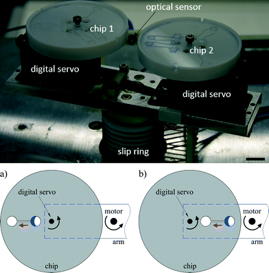
Based on the aforementioned limitations to the centrifugal format, we herein describe a novel two degrees of freedom (2-DoF) centrifugal microfluidic platform, which allows complex fluidic control in a direct manner and requires no external components. Since the addition of a second degree of freedom is facile and significantly enhances fluidic control, we expect that the approach will extend the use of centrifugal microfluidic technologies to more complex multi-step chemical and biological applications. In our platform, two microfluidic devices are installed on two digital servos and mounted on each side of a rotating arm driven by a motor. By adjusting the position of the digital servos, the centrifugal force applied on the liquid and the direction of its motion can be controlled (Fig. 1). We demonstrate the versatility of this platform by showing how the addition of a second degree of freedom allows the unconstrained and reversible pumping of liquid in both radial directions, the independent opening of burst valves relying on the chip position (rather than the architectural design or rotational speed) and the on-demand switching of flow between several different target chambers. During the preparation of this manuscript we noticed that Miao et al. and Geissler et al. have recently shown platforms where a turn table and a stepper motor were used to change the position of the centrifugal microfluidic device to allow localized heating31 and to accomplish basic inward pumping, respectively.32 However, in this work we show the full potential and versatility of 2-DoF centrifugal microfluidic platforms to achieve complex fluid control, demonstrate for the first time their use to access independent burst valves and achieve targeted flow switching, and provide design rules to allow simple designs for challenging fluidic actions to be adapted to suit different applications.
Experimental methods
Two degrees of freedom centrifugal microfluidic platform
To create a 2-DoF centrifugal microfluidic platform (Fig. 1), two devices are installed on two digital servos (MX-12A, ROBOTIS, South Korea), which are fixed at the two ends of an arm driven by a motor (ASD-A2, Delta Electronics, Taiwan). Power supply and communication to the digital servos are realized through a custom designed slip-ring (Moflon Technology Shenzhen, China) fixed on the shaft of the motor. The motor rotates the arm to generate centrifugal force, and the digital servos change the rotational (not translational) position of each device relative to the centre of rotation of the motor. At each end of the arm, a small bar is used to trigger an optical sensor (FS-V11P, Kencycle Enterprise, China). When the bar passes through the field of view of the sensor, a pulse signal triggers a high-speed camera (Dalsa HM1400, Stemmer Imaging, Switzerland). This requires that the motor rotates the arm at 200 rpm throughout the experiment to allow imaging. This spin speed does not cause liquid transport in our designs. Lighting is provided by an adjustable high-intensity fiber-coupled illuminator (OSL2, Thorlabs, Germany). An in-house control program was written using LabVIEW 2014, with position and speed commands to the motor and digital servo being sent through an RS-232 interface. It is important to note that the electromagnetic field from the motor interferes with the communication to the digital servo when the baud rate is set excessively high (such as 20![[thin space (1/6-em)]](https://www.rsc.org/images/entities/char_2009.gif) 000 s−1). Here the baud rate is set to 8000 s−1.
000 s−1). Here the baud rate is set to 8000 s−1.
Chip fabrication
For inward pumping and flow switching experiments, centrifugal microfluidic devices were made of PMMA (polymethylmethacrylate) and structured using a CNC milling machine (Optimum, Stadelmann Maschinen AG, Switzerland). This allowed the direct fabrication of channels with cross sectional dimensions of 500 × 500 μm. The diameter and depth of the chambers used in all experiments were 4 mm and 1.5 mm, respectively. PMMA devices are covered with transparent tape (Scotch, 3M, Switzerland) to provide fluidic integrity and ensure that the devices could be reused after cleaning.13 For the experiments involving the assessment of independent burst valves, microfluidic devices were made of polydimethylsiloxane (PDMS) using standard soft lithographic techniques.33 This allowed the facile creation of structures with feature sizes as small as 30 μm. AutoCAD (Autodesk, 2016) files of the designs used for burst valves and 3D models (step format) for inward pumping and flow switching are provided in the ESI.†Results and discussion
Inward pumping
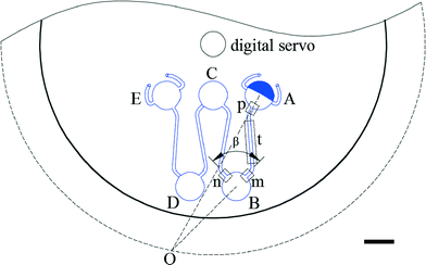
The basic design required to achieve inward pumping between different chambers in the 2-DoF centrifugal microfluidic platform involves aligning the channel exiting the chamber containing the liquid to be pumped with the centre of the motor. Such a design, fabricated using PMMA, is shown in Fig. 2, where five densely packed chambers are connected in series, with alternate chambers being located at the edge and centre of the microfluidic device respectively.Air vents are only required on the chambers at the start and end of a chain, with each chamber being connected to its neighbours by a channel containing two segments. The channel design depends on whether the chamber is at the end or in the middle of the chain. For chambers between the initial and final chambers, the angle, β, between the two channels connected to a given chamber is designed to be at least 90°, so as to avoid driving the fluid into the opposite channel (channel segments m and n in Fig. 2, for example). The angle between channel segments m and t (which connect chamber A to chamber B) was also designed to be greater than 90° to avoid residual liquid collecting at the junction of the two channels.
The short channel segments exiting chambers A and E (the initial and final chambers) are designed so that the fluid cannot be “accidentally” pumped out of the air vents. To ensure this feature, a line drawn from channel segment p, the exit channel of chamber A, for example, should be co-linear with the motor, as should the entrance channel for the next chamber, in this case channel segment m leading to chamber B. This means that lines extending from segments p and m must intersect at a point on a circle with a radius corresponding to the distance between the centres of the digital servo and the motor. Accordingly, when the fluid is pumped from chamber B to chamber A (or from chamber D to chamber E), it will not be driven out through the air vents.
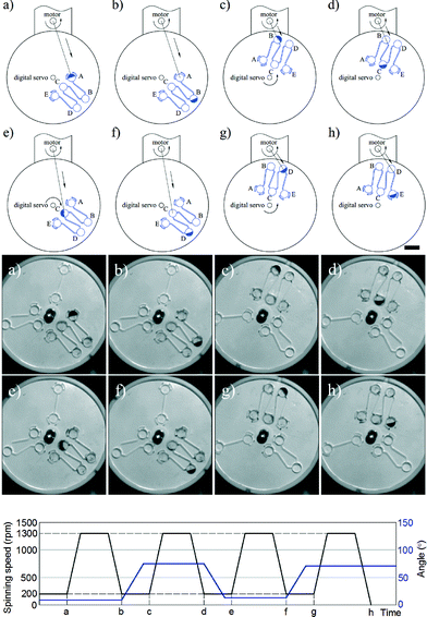
The two steps required to pump liquid between chambers (radially inwards and radially outwards) are aligning and spinning. First, the device is positioned using the digital servo so that the short channel at the exit of the chamber initially holding the fluid is collinear with the centre of the motor. Then, the device is rotated (using the motor) to cause liquid transfer into the target chamber. This process is shown in detail in Fig. 3 and in Video S1 in the ESI.† It is important to note that although five chambers are used in the current example, there is no limit on the number of chambers that can be used as long as the design parameters described above are obeyed. It is interesting to note that previous studies only pump fluids between a maximum of 3 chambers. For example, Salin et al. managed to pump liquid radially inwards and outwards using an external gas cylinder between multiple chambers but in an irreversible fashion.2
Since pumping between chambers requires two operations with device rotation occurring in both, the optimum spin speeds for each step were determined to ensure full control over the fluid position and to avoid unwanted leakage. As shown in Fig. 3, a rotational speed of 1300 rpm ensures that the fluid is driven into the target chamber. During adjustment of the chip position, the spin speed of the motor is decreased until the centrifugal force is insufficient to drive the fluid from the chamber (200 rpm in these experiments to allow continuous imaging of the chip) and during alignment the digital servo spins at 200 rpm. Video S1 in the ESI† shows the process of inward and outward pumping from the initial (A) to the final (E) chamber and back. The data presented herein shows controllable, reproducible and reversible pumping between 5 chambers, both radially inwards and radially outwards using a 2-DoF centrifugal microfluidic platform. In all cases, the liquid is transferred efficiently between the chambers.
Independent burst valves
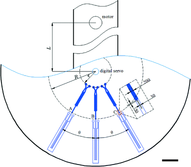
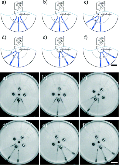
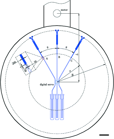
The second degree of freedom added to a centrifugal microfluidic platform by the addition of a digital servo can also be used to access identical burst valves independently. To demonstrate this feature, three identical burst valves were placed on a circular path in a centrifugal microfluidic device fabricated using PDMS, separated by the same angle, θ (Fig. 4). Using a uniform rotational speed of the motor, the burst valve that is co-linear with the centre of the motor experiences the highest pressure and hence bursts open, whilst all other (identical) valves in the microfluidic platform remain closed. Accordingly, using the digital servo to adjust the position of the chip allows each valve to be opened independently when the applied pressure is larger than the threshold value for the valve.The burst valves consist of a narrow channel with a height and width of 30 μm accessed by a rectangular expanding structure (see the inset in Fig. 4). The pressure, P, applied to the fluid held in this rectangular structure by the unopened valve is given by,
P = ρω2[R + r + 2L![[thin space (1/6-em)]](https://www.rsc.org/images/entities/char_2009.gif) cos cos![[thin space (1/6-em)]](https://www.rsc.org/images/entities/char_2009.gif) (θ)](R − r)/2 (θ)](R − r)/2 | (1) |
Eqn (1) shows that the pressure decreases with the value of θ, and therefore when θ is 0 the pressure reaches its highest value. This means that when the channel leading to a burst valve is co-linear with the centre of the motor, that burst valve is subjected to the highest pressure upon rotation. Hence, to independently operate the identical burst valves, in a fashion analogous to the steps required for inward pumping described above, two steps are required. First, the digital servo is used to align the target valve such that it is co-linear with the motor, and then the motor rotates the chip until the valve is opened (Fig. 5 and Video S2 in the ESI†).
The opening pressure threshold of the burst valves with the same dimensions lies over a range of values (Pmin to Pmax). When valve B, for example, is collinear with the centre of the motor, the pressure in valve B should be higher the highest threshold (Pmax) and the pressure in valves A and C should be lower than the lowest threshold (Pmin), as shown in eqn (2):
 | (2) |
 | (3) |
In the current experiments, the threshold pressure of the burst valves is between 2797 and 3054 Pa, and according to eqn (3) the range of operational spin speeds is between 843 and 855 rpm. Accordingly, the spin speed was set to 850 rpm.
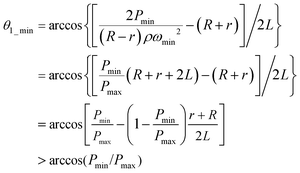
The minimum angle between adjacent burst valves for design 1, θ1_min, determines the density of valves that can be integrated into a single device. From eqn (2) we find that:
 | (4) |
 | (5) |
Therefore, the highest density of identical burst valves that can be designed in a single centrifugal microfluidic platform and still be accessed independently can be predicted. In our experiments, θ1_min is calculated as 26.25°, and we therefore designed θ to be 30°.
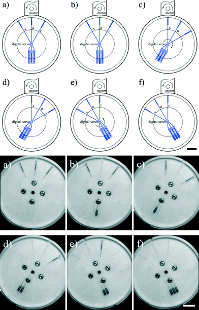
In the design shown in Fig. 5 (design 1), the working ranges of the spin speed and the valve density are both relatively narrow. An alternate design is shown in Fig. 6 (design 2), where the burst valves are designed such that they sit between the centres of the digital servo and the motor rather than on the edge of the chip as in design 1. The working principles are the same as in design 1, and hence the pressure applied on the valve is:
P = ρω2(R − r)[2L![[thin space (1/6-em)]](https://www.rsc.org/images/entities/char_2009.gif) cos cos![[thin space (1/6-em)]](https://www.rsc.org/images/entities/char_2009.gif) (θ) − R − r]/2 (θ) − R − r]/2 | (6) |
This pressure also decreases with the angle, θ, which means that the burst valve is subjected to the highest pressure when the channel connected to the burst valve is co-linear with the centre of the motor. Hence, aligning the channel of the target valve to ensure that it is co-linear with the centre of the motor and application of the required motor spin speed enables independent operation of the burst valves as shown in Fig. 7 and Video S3 in the ESI.†
In a similar manner to design 1, the working range of spin speeds (eqn (7) and (8)) and the minimum angle between the valves (eqn (9) and (10)) can be calculated, i.e.
 | (7) |
 | (8) |
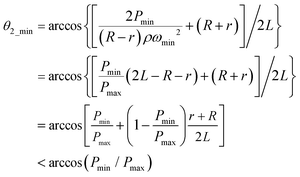
 | (9) |
 | (10) |
In this design, the working range is increased to between 1512 rpm and 1909 rpm, and θ2_min (the minimum angle between adjacent burst valves for design 2) decreases to 13.2°, allowing more efficient packing of the burst valves in the centrifugal microfluidic platform.
This is calculated using eqn (3) and (8), so that we can calculate the ratio of maximum and minimum spin speeds for both designs:
 | (11) |
 | (12) |
 | (13) |
Thus in design 2, the working range of spin speeds is wider than that in design 1. From eqn (5) and (10), we can show that design 2 can operate with a higher density of burst valves than design 1:
| θ2_min < arccos (Pmin/Pmax) < θ1_min | (14) |
Flow switching
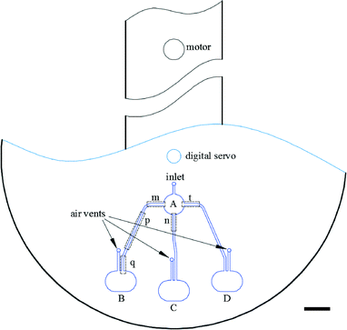
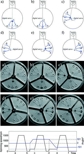
A final example of the enhanced control over the fluid position in 2-DoF centrifugal microfluidic platforms is flow switching. Here, flow switching means choosing the chamber into which fluid will be pumped from a given starting chamber. In the design shown in Fig. 8 there are three target chambers (B, C and D) on the outside edge of the device and one original chamber (A) near the centre of the chip. The steps required to achieve pumping of the fluid into the targeted chamber are again aligning and spinning. When channels m, n or t are co-linear with the motor the fluid will be pumped into chambers B, C and D respectively (as shown in Fig. 9). Compared with previously published work on traditional centrifugal microfluidic platforms,28–30 flow switching in a 2-DoF centrifugal microfluidic platform is performed at lower spin speeds and in a configurable manner.The design parameters required for flow switching to work in this 2-DoF centrifugal microfluidic platform are simple. The angles between all the channels exiting the input chamber (chamber A) are set to 90°. These are shown as the angles between channels m and n, and between channels n and t in Fig. 8. There is an air vent in each of the target chambers (chambers B, C and D) with each designed to be parallel with the channel that functions as the inlet to the target chamber, to ensure that no fluid exits through the air vents. At every junction between different segments of a single channel, the angles are designed to be larger than 90° to avoid residual fluid collecting at the junction of the two channels (such as the junction of channel segments p and q in Fig. 8). The targeted dosing of selected chambers from a common input chamber is shown in detail in Fig. 9 and in Video S4 in the ESI.†
Conclusions
Herein we have shown a novel centrifugal microfluidic platform with two degrees of freedom, instead of the single degree of freedom common in traditional centrifugal platforms. This additional degree of freedom allows fluidic operations that were previously deemed either excessively complex or inaccessible to be easily and reproducibly performed in a configurable manner. We demonstrate efficacy by performing three basic fluidic operations, namely controllable inward pumping, opening of independent burst valves and targeted flow switching. We demonstrate the ability to pump fluids efficiently in a fully reversible fashion between multiple chambers using no external equipment. The improved fluidic control enables burst valves to be operated independently from each other, even when they have an identical structure. Two designs for burst valves were tested to show the validity of the mathematical model used in the design process. This model allows the valve design to be adjusted such that the valve density and the range of spin speeds can be targeted towards a specific application. Finally, we show how the addition of a second degree of freedom allows flow switching between several target chambers. Since the addition of a second degree of freedom is simple, inexpensive, can be accomplished by minimal modifications to traditional centrifugal microfluidic platforms and provides significant advantages with regard to fluid control, we envision that 2-DoF centrifugal microfluidic platforms will become the norm for studies performed on centrifugal microfluidic platforms in the near future.Notes and references
- D. Mark, S. Haeberle, G. Roth, F. von Stetten and R. Zengerle, Chem. Soc. Rev., 2010, 39, 1153–1182 RSC.
- M. C. R. Kong and E. D. Salin, Anal. Chem., 2010, 82, 8039–8041 CrossRef CAS PubMed.
- J. Steigert, M. Grumann, T. Brenner, L. Riegger, J. Harter, R. Zengerle and J. Ducree, Lab Chip, 2006, 6, 1040–1044 RSC.
- D. Mark, F. von Stetten and R. Zengerle, Lab Chip, 2012, 12, 2464–2468 RSC.
- S. Haeberle and R. Zengerle, Lab Chip, 2007, 7, 1094–1110 RSC.
- R. Gorkin, J. Park, J. Siegrist, M. Amasia, B. S. Lee, J. M. Park, J. Kim, H. Kim, M. Madou and Y. K. Cho, Lab Chip, 2010, 10, 1758–1773 RSC.
- N. Honda, U. Lindberg, P. Andersson, S. Hoffmann and H. Takei, Clin. Chem., 2005, 51, 1955–1961 CAS.
- Y.-K. Cho, J.-G. Lee, J.-M. Park, B.-S. Lee, Y. Lee and C. Ko, Lab Chip, 2007, 7, 565–573 RSC.
- M. Focke, F. Stumpf, B. Faltin, P. Reith, D. Bamarni, S. Wadle, C. Müller, H. Reinecke, J. Schrenzel and P. Francois, Lab Chip, 2010, 10, 2519–2526 RSC.
- W. Espulgar, W. Aoki, T. Ikeuchi, D. Mita, M. Saito, J.-K. Lee and E. Tamiya, Lab Chip, 2015, 15, 3572–3580 RSC.
- R. Gorkin, J. Park, J. Siegrist, M. Amasia, B. S. Lee, J.-M. Park, J. Kim, H. Kim, M. Madou and Y.-K. Cho, Lab Chip, 2010, 10, 1758–1773 RSC.
- A. H. Ng, U. Uddayasankar and A. R. Wheeler, Anal. Bioanal. Chem., 2010, 397, 991–1007 CrossRef CAS PubMed.
- S. Zehnle, F. Schwemmer, G. Roth, F. von Stetten, R. Zengerle and N. Paust, Lab Chip, 2012, 12, 5142–5145 RSC.
- R. Gorkin, L. Clime, M. Madou and H. Kido, Microfluid. Nanofluid., 2010, 9, 541–549 CrossRef.
- K. Abi-Samra, L. Clime, L. Kong, R. Gorkin, T. H. Kim, Y. K. Cho and M. Madou, Microfluid. Nanofluid., 2011, 11, 643–652 CrossRef CAS.
- T. H. G. Thio, F. Ibrahim, W. Al-Faqheri, J. Moebius, N. S. Khalid, N. Soin, M. K. B. A. Kahar and M. Madou, Lab Chip, 2013, 13, 3199–3209 RSC.
- S. Soroori, L. Kulinsky, H. Kido and M. Madou, Microfluid. Nanofluid., 2013, 1–13 Search PubMed.
- D. C. Duffy, H. L. Gillis, J. Lin, N. F. Sheppard and G. J. Kellogg, Anal. Chem., 1999, 71, 4669–4678 CrossRef CAS.
- M. J. Madou, L. J. Lee, S. Daunert, S. Lai and C.-H. Shih, Biomed. Microdevices, 2001, 3, 245–254 CrossRef CAS.
- J.-M. Park, Y.-K. Cho, B.-S. Lee, J.-G. Lee and C. Ko, Lab Chip, 2007, 7, 557–564 RSC.
- J. Siegrist, R. Gorkin, L. Clime, E. Roy, R. Peytavi, H. Kido, M. Bergeron, T. Veres and M. Madou, Microfluid. Nanofluid., 2010, 9, 55–63 CrossRef.
- J. Ducrée, S. Haeberle, S. Lutz, S. Pausch, F. Von Stetten and R. Zengerle, J. Micromech. Microeng., 2007, 17, 103–115 CrossRef.
- H. Cho, H.-Y. Kim, J. Y. Kang and T. S. Kim, J. Colloid Interface Sci., 2007, 306, 379–385 CrossRef CAS PubMed.
- P. Andersson, G. Jesson, G. Kylberg, G. Ekstrand and G. Thorsén, Anal. Chem., 2007, 79, 4022–4030 CrossRef CAS PubMed.
- L. G. Puckett, E. Dikici, S. Lai, M. Madou, L. G. Bachas and S. Daunert, Anal. Chem., 2004, 76, 7263–7268 CrossRef CAS PubMed.
- S. Lutz, P. Weber, M. Focke, B. Faltin, J. Hoffmann, C. Müller, D. Mark, G. Roth, P. Munday and N. Armes, Lab Chip, 2010, 10, 887–893 RSC.
- T. Kawai, N. Naruishi, H. Nagai, Y. Tanaka, Y. Hagihara and Y. Yoshida, Anal. Chem., 2013, 85, 6587–6592 CrossRef CAS PubMed.
- T. Brenner, T. Glatzel, R. Zengerle and J. Ducrée, Lab Chip, 2005, 5, 146–150 RSC.
- J. Kim, H. Kido, R. H. Rangel and M. J. Madou, Sens. Actuators, B, 2008, 128, 613–621 CrossRef CAS.
- M. C. Kong and E. D. Salin, Anal. Chem., 2011, 83, 1148–1151 CrossRef CAS PubMed.
- B. Miao, N. Peng, L. Li, Z. Li, F. Hu, Z. Zhang and C. Wang, Sensors, 2015, 15, 27954–27968 CrossRef CAS PubMed.
- M. Geissler, L. Clime, X. D. Hoa, K. J. Morton, H. Hébert, L. Poncelet, M. Mounier, M. Deschênes, M. E. Gauthier and G. Huszczynski, Anal. Chem., 2015, 87, 10565–10572 CrossRef CAS PubMed.
- Y. Xia and G. M. Whitesides, Annu. Rev. Mater. Sci., 1998, 28, 153–184 CrossRef CAS.
Footnote |
| † Electronic supplementary information (ESI) available: Video S1 – inward pumping, Video S2 – independent burst valves (design 1), Video S3 – independent burst valves (design 2), and Video S4 – flow switching. CAD files of designs for two types of independent burst valves, inward pumping and flow switching modules. See DOI: 10.1039/c5lc01530h |
| This journal is © The Royal Society of Chemistry 2016 |

