Controllable generation and encapsulation of alginate fibers using droplet-based microfluidics†
Chiara
Martino
*,
Cyril
Statzer
,
Daniele
Vigolo‡
and
Andrew J.
deMello
*
Department of Chemistry and Applied Biosciences, Institute for Chemical and Bioengineering, ETH Zurich, Vladimir Prelog Weg 1, Zürich 8093, Switzerland. E-mail: andrew.demello@chem.ethz.ch; chiara.martino@chem.ethz.ch
First published on 6th November 2015
Abstract
Herein we demonstrate the segmentation of alginate solution streams to generate alginate fibers of precisely controllable lengths between 200 and 1000 μm. Moreover, we demonstrate the subsequent encapsulation of the formed fibers within pL-volume microdroplets, produced within the same microfluidic device, in a direct manner. Finally, we show immediate and complete on-chip gelation of alginate fibers in a rapid and reproducible fashion.
1 Introduction
Over the last decade, the fabrication of fibrous structures on the micron scale has found numerous applications in the field of regenerative medicine1 and tissue engineering.2 In this regard, microfluidics has proved to be of great utility in generating chemically complex structures of tuneable geometry and in the handling of associated biomaterials.3,4 Amongst a great variety of naturally-derived materials used for hydrogel generation in biomedical applications5 (such as hyaluronic acid, chondroitin sulfate, chitin, chitosan, gelatin and alginate) alginate-based materials have gained particular popularity for the generation of fibrous structures.3 Alginate is a naturally derived polysaccharide, which is soluble in aqueous solutions and undergoes gelation when exposed to cations such as Ca2+.6 Once cross-linked, alginate forms a three-dimensional (3D) elastic network with high water content, representing a favourable substrate in which to mimic the extracellular matrix (ECM) in artificial cell systems.7 Moreover, facile gelation, the ability of this material to hold live cells (such as fibroblasts,8 myoblasts9 and neuronal cells10) and its biocompatibility, are key properties that have been widely exploited in various fields including drug delivery,11 food formulation12,13 and tissue engineering.5,14Microfluidic systems have proved particularly advantageous in allowing the fabrication of alginate hydrogels in a rich variety of geometries. Indeed, to date, alginate spheres,15,16 core–shell structures,7,17,18 tear-drops,19,20 yarn-ball geometries,21 full fibers,22–24 hollow fibers25 and patterned fibers10 have all been successfully synthesized. However, it is noted that to date no method that allows the production and in situ encapsulation of alginate fibers of defined length has been reported.
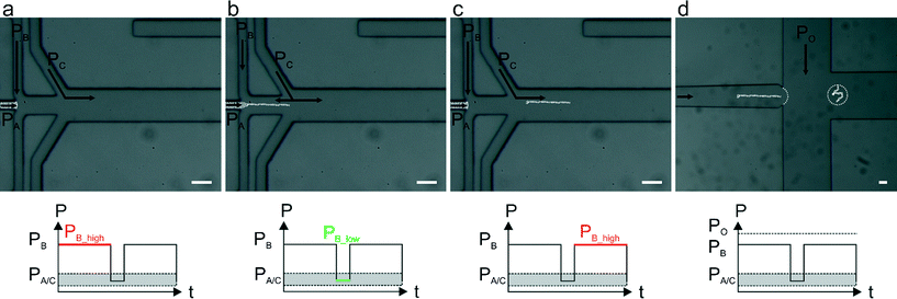
Alginate solutions exhibit viscoelastic shear-thinning behaviour, meaning that viscosity decreases with increasing strain rate.26 On the molecular level, the long polymeric chains align when they are sheared and are able to slide along one another under high strain rate,27 hence making alginate jet cutting inherently difficult. Herein, we present a strategy that allows: (i) the separation of a jet of alginate precursor solution prior to crosslinking, (ii) the immediate and complete gelation of alginate segments that prevents non-specific surface adhesion (which leads to fiber deformation and ultimately channel blockage) and (iii) the encapsulation of alginate fibers within pL-volume droplets generated within the same microfluidic device (Fig. 1).
By applying a pulsatile pressure regime to a sheathing buffer solution (defined as PB in Fig. 1), tuned to the alginate solution viscosity, we are able to periodically cut the alginate jet (controlled by PA). The alginate solution fragment travels into the polymerization channel where it first meets a buffer stream containing Ca2+ ions (Fig. 1b and c) and subsequently an oil stream (controlled by PO in Fig. 1d) that is responsible for encapsulating the formed fibers into droplets. In contrast to prior studies that utilize a device-embedded valve for “cutting” polyethylene (glycol) diacrylate (400 Da) jets at pressures above 2 bar,28 we are able to achieve cutting using pressures of only a few mbars, hence not affecting the downstream flows. Such an approach not only allows direct alginate segmentation but is also compatible with downstream droplet generation within the same microfluidic device. A detailed comparison between the presented approach and a lateral valve approach used for controlling polyethylene (glycol) diacrylate fiber lengths is presented in the (ESI†).
2 Experimental
Materials
A 1% (w/w) sodium alginic acid salt solution was supplemented with fluorescent beads (F8809, FluoSpheres, carboxylate-modified orange 540/560, 0.2 μm, Life Technologies, Switzerland). A 10% (w/w) dextran solution (31392 from Leuconostoc SPP, Mr 450![[thin space (1/6-em)]](https://www.rsc.org/images/entities/char_2009.gif) 000–650
000–650![[thin space (1/6-em)]](https://www.rsc.org/images/entities/char_2009.gif) 000, Sigma-Aldrich, Switzerland) and a 10% (w/w) dextran solution supplemented with 100 mM CaCl (Sigma-Aldrich, Switzerland) were used as sheathing and polymerizing buffers respectively. Droplets were generated using a mineral oil continuous phase (M3516, Sigma-Aldrich, Switzerland) containing 2% (w/w) Span80 (S6770, Sigma-Aldrich, Switzerland).
000, Sigma-Aldrich, Switzerland) and a 10% (w/w) dextran solution supplemented with 100 mM CaCl (Sigma-Aldrich, Switzerland) were used as sheathing and polymerizing buffers respectively. Droplets were generated using a mineral oil continuous phase (M3516, Sigma-Aldrich, Switzerland) containing 2% (w/w) Span80 (S6770, Sigma-Aldrich, Switzerland).
All solutions were regulated using a pressure controller (OB1, Elveflow, France) in combination with proprietary software (Elveflow Smart Interface, Elveflow, France). The pressure ranges for the alginate precursor solution, sheathing buffer, calcium solution and oil were 80–130 mbar, 40–190 mbar, 100–170 mbar and 200–500 mbar respectively. The lateral valve (used in control experiments) was actuated with a customised solenoid valve system (MH1, Festo, Switzerland) with applied pressures ranging from 100 to 3000 mbar.
Experimental setup
The microfluidic device design includes inlet channels for reagent delivery, a 1 cm long polymerization channel, a cross junction for droplet generation and a lateral valve (used for the control experiments described in the ESI†). Devices were produced using standard soft lithographic methods29 in polydimethylsiloxane (PDMS). The PDMS base and curing agent (Sylgard 184, Dow Corning, USA) were mixed at a ratio of 17![[thin space (1/6-em)]](https://www.rsc.org/images/entities/char_2009.gif) :
:![[thin space (1/6-em)]](https://www.rsc.org/images/entities/char_2009.gif) 1 (w/w), degassed and decanted onto the master. The entire structure was cured in the oven at 70 °C overnight and then peeled off the master. After punching inlet and outlet vias, the structured PDMS layer was irreversibly bonded to a clean coverglass slide (76 mm × 26 mm × 1 mm, Menzel Gläser, USA) after exposing the two surfaces to an oxygen plasma (Dieter Electronics, USA) and cured on a hot plate at 120 °C for 1 hour. To limit unwanted alginate deposition on microchannel surfaces all devices were passivated with a 1% (w/w) solution of Pluronic F-127 (P2443, Sigma-Aldrich, Switzerland) in DPBS (14190, Life Technologies, Switzerland) for 1 hour and kept at 70 °C to dry.
1 (w/w), degassed and decanted onto the master. The entire structure was cured in the oven at 70 °C overnight and then peeled off the master. After punching inlet and outlet vias, the structured PDMS layer was irreversibly bonded to a clean coverglass slide (76 mm × 26 mm × 1 mm, Menzel Gläser, USA) after exposing the two surfaces to an oxygen plasma (Dieter Electronics, USA) and cured on a hot plate at 120 °C for 1 hour. To limit unwanted alginate deposition on microchannel surfaces all devices were passivated with a 1% (w/w) solution of Pluronic F-127 (P2443, Sigma-Aldrich, Switzerland) in DPBS (14190, Life Technologies, Switzerland) for 1 hour and kept at 70 °C to dry.
All optical measurements were performed using an inverted microscope (Nikon Eclipse Ti-E, Nikon, Japan) equipped with a digital camera (Orca-Flash 4.0, Hamamatsu, Japan) and a light source (LED, Prior Scientific, United Kingdom) for bright field illumination. For fluorescence measurements a mercury light source (Intensilight C-HGFI, Nikon, Japan) in combination with a Tetramethylrhodamine (TRITC) filter set (F26-516, AHF analysentechnik AG, Germany) was utilized. Images were acquired using proprietary software (HCImageLive 4.0.3.6, Hamamatsu, Japan).
Fiber lengths were calculated from fluorescence signals recorded at the cross junction (Fig. 1d), and fiber length quantification automatically processed using a script written in ImageJ 1.48v (NIH, USA). Additional details regarding analysis are provided in the ESI.†
3 Results and discussion
Synthesis of alginate fibers with different lengths
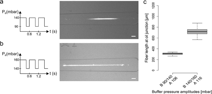
To control alginate fiber generation we explored various pulsing regimes that led to the production of fiber length ranging from few hundreds of microns to a few millimetres. The pressures associated with the calcium chloride solution (PC) and oil (PO) were kept constant across all the measurements (110 mbar and 350 mbar respectively), with PC set at a value between PB_low and PB_high. Moreover, the alginate solution pressure (PA) was essentially kept constant but, according to the chosen ΔPB for each experiment, PA was marginally adjusted to avoid alginate backflow.Fig. 2 illustrates representative data produced by two different pulsing regimes. In each regime, we applied an identical pulsation period and duty cycle (i.e. the fraction of time in which the pressure is kept high compared to the total period time) but different PB pressure values (PB_low /PB_high). As shown in Fig. 2a and b, PB followed a square wave signal with a period of 0.6 s and a 68% duty cycle, and PB pressures were set at 90/140 mbar (Fig. 2a) and 140/160 mbar (Fig. 2b). It can be seen that variation of PB led to a significant change in the fiber length, producing average fiber lengths of 309 ± 17 μm and 717 ± 72 μm (extracted from between 100 replicate measurements; Fig. 2c).
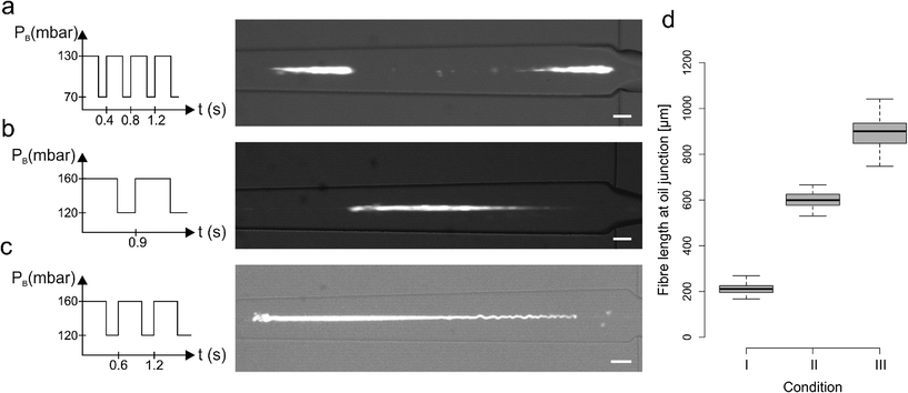
We also investigated the combined effect of changing the pulsation period and PB pressure values whilst maintaining a constant duty cycle of 68%. Fig. 3a–c shows three different conditions that generate fibers of distinct lengths. In these experiments, PB followed a square wave signal with a period of 0.4 s and values set to 70/130 mbar (Fig. 3a and condition I in Fig. 3d), a period of 0.9 s and values set to 120/160 mbar (Fig. 3b, condition II in Fig. 3d) and a period of 0.6 s and values set to 120/160 mbar (Fig. 3c, condition III in Fig. 3d). As shown in Fig. 3d, such operating conditions generated fibers with lengths ranging from approximately 200 to 1000 μm.
A more detailed summary of the variety of conditions analysed is presented in the ESI† and demonstrates that an increase in PB_low, and a consequent increase of PA, leads to a fiber length increase. Nevertheless, it is important to note that it is difficult to establish a strict relation between a single parameter and the alginate fiber length, since the experimental parameters are interdependent and cannot easily be changed in isolation. However, it is clear that the combination of a pulsatile sheathing buffer pressure and the spatial proximity of the sheathing buffer and calcium influx is essential to segment the alginate jet. Furthermore, the immediate calcium exposure favours fiber gelation over the re-joining of two consecutive un-polymerised alginate segments, with the backflow of Ca2+ ions in the buffer channel guaranteeing fast gelation of each alginate segment.
Synthesis of patterned alginate fibers
As previously noted, a mild backflow of Ca2+ ions in the sheathing buffer channel accelerates alginate polymerization without causing alginate deposition. However, if PA is increased and the lower buffer pressure (PB_low) decreased, the precursor alginate solution is able to flow into the sheathing buffer channel where it polymerizes leaving an imprint on the alginate fiber. Fig. 4a–f shows a time sequence of a single cycle whilst Fig. 4g shows an alginate fiber containing repetitive units obtained from channel imprinting after two cycles. Fibers were generated with PA = 129 mbar, PB = 40/160 mbar and a period and duty cycle equal to 0.6 s and 68% respectively.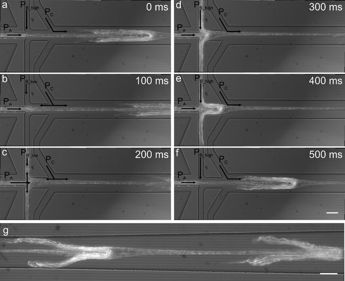 | ||
| Fig. 4 Generation of regularly patterned alginate fibers. A variation of the operating conditions imposed in Fig. 2b leads to the production of a continuous alginate fiber displaying regular dispersed protrusions. This is achieved by increasing ΔPB and increasing the alginate pressure. Starting from the pressure conditions in Fig. 2b, by decreasing the PB_low to 40 mbar and increasing the alginate pressure to 129 mbar the alginate solution and Ca2+ ions flow into the sheathing buffer channel and initiate gelation (a–c); as soon as the PB becomes higher, the polymerised alginate is pushed out forming a fiber containing imprinted features (d–f) which flows downstream (g). Scale bars are equal to 50 μm. | ||
Fiber encapsulation
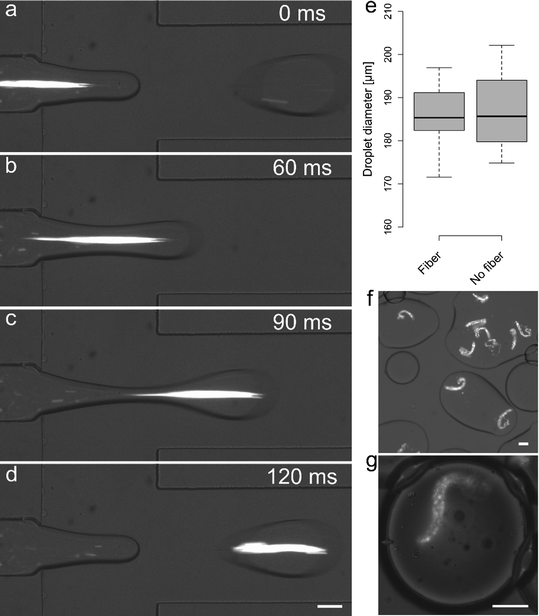
Alginate fibers generated by using PA = 109 mbar and PB = 100/160 mbar with period equal to 0.4 s, a 50% duty cycle and Pc = 110 mbar could be directly encapsulated into pL-volume droplets. PO was set to 350 mbar and droplets of an average diameter of 186 μm (C.V. = 5%) were produced at a frequency of 8.4 Hz. Fig. 5a–d shows representative time frames during the encapsulation of a 300 μm long alginate fiber. Under the current operating conditions one out of three droplets could be loaded with an in situ generated fiber. As shown in Fig. 5e, the fiber encapsulation process does not affect droplet diameter. Moreover, small variations in oil pressure (±10%) did not affect upstream fiber generation, thus allowing control over both droplet size and fiber encapsulation. To ascertain whether gelation of the alginate fiber occurred within the device, a drop (100 μL) of the emulsion produced on-chip was deposited and smeared onto a coverglass slide (Fig. 5f). No significant deformation in fiber shape could be observed and imaging of droplets containing alginate fibers 1 hour after generation confirmed that alginate fiber shape was identical to that observed during encapsulation (Fig. 5g).Fouling
Fouling is a common problem encountered in microfluidic devices, especially when directly bonded on glass surfaces since glass has a very high nonspecific binding capacity for proteins and other biomolecules.30 A number of methods have been developed to limit this problem.31 In this work, surface treatment with Pluronic-127 was successful in preventing fouling when compared to uncoated devices. The time until the first alginate deposition occurred increased from approximately 1 minute, in uncoated devices, to between 5 and 10 minutes when coated with Pluronic-127. Furthermore, fouling on the coated surface displayed a much weaker attachment and, thus could be removed immediately by the next fiber. We also observed that this “self-cleaning” effect was more efficient when the diameter of the polymerization channel was smaller, since the fiber was less likely to pass around the attached fibers. If such a self-cleaning process proved ineffective, an increase in alginate pressure for two seconds was used to purge the polymerization channel, giving the devices a working lifetime of up to 60 minutes.4 Conclusions
In this work, we present a new microfluidic strategy to segment an alginate precursor solution and generate alginate fibers. The combined effects of pulsatile pressure control and immediate exposure to a buffer solution containing Ca2+ ions are responsible for the generation of alginate fibers of different lengths, ranging from a few hundreds of microns to up to one millimetre. Alginate fibers of different length are of potential utility in culturing small cell populations in spatially defined environments and in a high-throughput manner, thus enabling hydrogel-shape dependent studies of cellular behaviour (as well as unlocking potential applications in biofabrication). Our approach is highly successful in achieving fast alginate gelation over very short distances, which in turn allows the encapsulation of polymerised fibers within the same microfluidic device. This feature will be particularly interesting in droplet-based application, for example for the generation of artificial cell constructs32,33 containing inner scaffolding. In this way it is possible to generate systems that can mimic functions of cells like the presence of a membrane setting a boundary of an inner compartment of controlled and well defined geometry. We can predict that the construction of such entities not only will offer the possibility of replacing faulty biological components in individuals affected by severe pathologies, as it is already happening for microfabricated tissue engineering products,3 but will also facilitate the understanding of components of life by making from scratch.Acknowledgements
Chiara Martino acknowledges support from the ETH Zurich Postdoctoral Fellowship Program and Marie Curie Actions for People COFUND Program.References
- H. Onoe and S. Takeuchi, Drug Discovery Today, 2015, 20, 236–246 CrossRef CAS PubMed.
- A. Tamayol, M. Akbari, N. Annabi, A. Paul, A. Khademhosseini and D. Juncker, Biotechnol. Adv., 2013, 31, 669–687 CrossRef CAS PubMed.
- M. A. Daniele, D. A. Boyd, A. A. Adams and F. S. Ligler, Adv. Healthcare Mater., 2015, 4, 2–2 CrossRef CAS.
- K. Ren, Y. Chen and H. Wu, Curr. Opin. Biotechnol., 2014, 25, 78–85 CrossRef CAS PubMed.
- B. G. Chung, K.-H. Lee, A. Khademhosseini and S.-H. Lee, Lab Chip, 2012, 12, 45–59 RSC.
- I. Machida-Sano, M. Hirakawa, H. Matsumoto, M. Kamada, S. Ogawa, N. Satoh and H. Namiki, Biomed. Mater., 2014, 9, 025007 CrossRef PubMed.
- C. Martino, T. Y. Lee, S.-H. Kim and A. J. deMello, Biomicrofluidics, 2015, 9, 024101 CrossRef PubMed.
- K. Y. Lee, E. Alsberg, S. Hsiong, W. Comisar, J. Linderman, R. Ziff and D. Mooney, Nano Lett., 2004, 4, 1501–1506 CrossRef CAS PubMed.
- E. Alsberg, K. W. Anderson, A. Albeiruti, R. T. Franceschi and D. J. Mooney, J. Dent. Res., 2001, 80, 2025–2029 CrossRef CAS PubMed.
- Y. Kitagawa, Y. Naganuma, Y. Yajima, M. Yamada and M. Seki, Biofabrication, 2014, 6, 035011 CrossRef PubMed.
- T. W. Wong, J. Pharm. Pharmacol., 2011, 63, 1497–1512 CrossRef CAS PubMed.
- L. H. Pignolet, A. S. Waldman, L. Schechinger, G. Govindarajoo, J. S. Nowick and L. Ted, J. Chem. Educ., 1998, 75, 1430 CrossRef.
- A. Escarpa, Lab Chip, 2014, 14, 3213–3224 RSC.
- K. Y. Lee and D. J. Mooney, Prog. Polym. Sci., 2012, 37, 106–126 CrossRef CAS PubMed.
- S. Sugaya, M. Yamada, A. Hori and M. Seki, Biomicrofluidics, 2013, 7, 054120 CrossRef PubMed.
- W. H. Tan and S. Takeuchi, Adv. Mater., 2007, 19, 2696–2701 CrossRef CAS.
- P.-W. Ren, X.-J. Ju, R. Xie and L.-Y. Chu, J. Colloid Interface Sci., 2010, 343, 392–395 CrossRef CAS PubMed.
- J. Wu, T. Kong, K. W. K. Yeung, H. C. Shum, K. M. C. Cheung, L. Wang and M. K. T. To, Acta Biomater., 2013, 9, 7410–7419 CrossRef CAS PubMed.
- C. J. Martinez, J. W. Kim, C. Ye, I. Ortiz, A. C. Rowat, M. Marquez and D. Weitz, Macromol. Biosci., 2012, 12, 946–951 CrossRef CAS PubMed.
- Y. Hu, G. Azadi and A. M. Ardekani, Carbohydr. Polym., 2015, 120, 38–45 CrossRef CAS PubMed.
- A. Miyama, M. Yamada, S. Sugaya and M. Seki, RSC Adv., 2013, 3, 12299–12306 RSC.
- M. Yamada, S. Sugaya, Y. Naganuma and M. Seki, Soft Matter, 2012, 8, 3122–3130 RSC.
- E. Kang, S.-J. Shin, K. H. Lee and S.-H. Lee, Lab Chip, 2010, 10, 1856–1861 RSC.
- S.-J. Shin, J.-Y. Park, J.-Y. Lee, H. Park, Y.-D. Park, K.-B. Lee, C.-M. Whang and S.-H. Lee, Langmuir, 2007, 23, 9104–9108 CrossRef CAS PubMed.
- K. H. Lee, S. J. Shin, Y. Park and S.-H. Lee, Small, 2009, 5, 1264–1268 CrossRef CAS PubMed.
- R. A. Rezende, P. J. Bártolo, A. Mendes and R. M. Filho, J. Appl. Polym. Sci., 2009, 113, 3866–3871 CrossRef CAS.
- K. Brian, Micro- and Nanoscale Fluid Mechanics Transport in Microfluidic Devices, Cambridge University Press, 2009 Search PubMed.
- J. K. Nunes, K. Sadlej, J. I. Tam and H. A. Stone, Lab Chip, 2012, 12, 2301–2304 RSC.
- Y. N. Xia and G. M. Whitesides, Angew. Chem., Int. Ed., 1998, 37, 550–575 CrossRef CAS.
- P. K. Sorger, Nat. Biotechnol., 2008, 26, 1345–1346 CrossRef CAS PubMed.
- I. Banerjee, R. C. Pangule and R. S. Kane, Adv. Mater., 2011, 23, 690–718 CrossRef CAS PubMed.
- C. Martino, L. Horsfall, Y. Chen, M. Chanasakulniyom, D. Paterson, A. Brunet, S. Rosser, Y.-J. Yuan and J. M. Cooper, ChemBioChem, 2012, 13, 792–795 CrossRef CAS PubMed.
- C. Martino, S.-H. Kim, L. Horsfall, A. Abbaspourrad, S. J. Rosser, J. Cooper and D. A. Weitz, Angew. Chem., Int. Ed., 2012, 51, 6416–6420 CrossRef CAS PubMed.
Footnotes |
| † Electronic supplementary information (ESI) available. See DOI: 10.1039/c5lc01150g |
| ‡ Present address: School of Chemical Engineering, University of Birmingham, Edgbaston, Birmingham, B15 2TT, UK. |
| This journal is © The Royal Society of Chemistry 2016 |

