Synergistic effect of combined colloidal and organic fouling in membrane distillation: Measurements and mechanisms†
Wenli
Qin
abc,
Jianhua
Zhang
a,
Zongli
Xie
*b,
Derick
Ng
b,
Ying
Ye
c,
Stephen R.
Gray
a and
Ming
Xie
 *a
*a
aInstitute for Sustainability and Innovation, College of Engineering and Science, Victoria University, Melbourne, VIC 8001, Australia. E-mail: ming.xie@vu.edu.au; Tel: +61 (3) 9919 8174
bCSIRO Manufacturing, Private bag 10, Clayton South MDC, VIC 3169, Australia. E-mail: zongli.xie@csiro.au; Tel: +61 (3) 9545 2938
cInstitute of Marine Geology and Resource, Ocean College, Zhejiang University, Zhoushan, Zhejiang 316021, China
First published on 17th August 2016
Abstract
We examined the synergistic effect of combined fouling in MD process with three organic foulants – alginate, bovine serum albumin (BSA), and humic acid – in the presence of colloidal silica particles. Membrane fouling profiles were quantified by water flux decline and permeate conductivity. Mechanisms of the synergistic effect of combined fouling were revealed by light scattering measurements and infrared spectra of foulant–foulant interaction and foulant–membrane interaction. Membrane fouling morphology and element mapping provided further details of transport of colloidal silica particles and elucidated the mechanisms for silica-induced pore wetting. Specially, gelation of alginate formed an alginate layer on membrane surface and prevented penetration of silica particles into the membrane matrix, which was confirmed by silicon element mapping as well as infrared spectra. Adsorption of BSA protein by colloidal silica aggregates led to a sharp water flux decline and a partial pore wetting. Humic acid, forming a coil structure in high salinity, exhibited limited interaction with colloidal silica that penetrated into the membrane matrix and wetted membrane pores, thereby compromising the product water quality. Results showed that the combined organic fouling with colloidal silica particle not only deteriorated water production, but also compromised product quality by partial membrane wetting.
Water impactMembrane fouling and subsequent wetting hinders water production and quality in membrane distillation (MD). Real feed streams always contain varying foulants, including colloidal and organic foulants, which potentially leads to combined fouling. An in-depth understanding of the foulant–foulant, and foulant–membrane interactions can shed light on the fouling mechanisms during MD filtration and guide corresponding pre-treatment approaches to minimize MD fouling. |
1. Introduction
Membrane distillation (MD), a thermally-driven membrane process, holds promise in brine management. The discontinuous nature of water transport through a porous, hydrophobic membrane in the MD process ensures that water production is largely independent of the feed solution salinity. In addition, MD can offer complete rejection of all non-volatile constituents, such as ions, dissolved non-volatile organics, colloids, and pathogenic agents, in the feed solution. The MD process can be operated in four different configurations including vacuum, air gap, sweep gas, and direct contact membrane distillation (DCMD).1 In particular, the DCMD configuration is well suited for brine treatment and the concentration of valuable products, where water is the main distillate product. As a result, the MD process was proposed to treat a wide range of challenging saline waste streams, such as reverse osmosis (RO) brine,2–5 coal seam gas brine,6–8 drilling fluids from oil and gas exploration,9,10 sludge centrate,11–14 and diary streams.15,16 For instance, MD was demonstrated to be a feasible and effective process capable of consistently producing high quality distillate (conductivity less than 10 μS cm−1) from high salinity brines (70![[thin space (1/6-em)]](https://www.rsc.org/images/entities/char_2009.gif) 000 mg L−1 total dissolved solids) in a desalination plant. MD process was also capable of achieving high water recovery (more than 85%) from coal seam gas brine,6 and high ammonia concentration (at least four-fold) from pig manure.17
000 mg L−1 total dissolved solids) in a desalination plant. MD process was also capable of achieving high water recovery (more than 85%) from coal seam gas brine,6 and high ammonia concentration (at least four-fold) from pig manure.17
Despite the effectiveness and robustness of MD filtration, membrane fouling, even wetting, can be detrimental to the MD operation,18,19 which decreases the driving force for permeation and demands frequent interruptions to operating systems for membrane cleaning.20,21 For instance, organic fouling consisting mainly of proteins, lipids and carbohydrates, was found to cause severe membrane fouling and reduced ammonia recovery from manure streams.17 Efforts were made to quantify and elucidate the mechanisms during MD fouling.22 Previous studies suggested that the deposition of various foulants onto the membrane surface not only reduced the vapour pressure difference through the membrane, but also changed the hydrophilicity of the membrane surface, thereby initiating pore wetting and compromising product water quality.23–25 Consequently, strategies to control MD fouling were proposed, including pre-treatments and advanced membrane surface modifications for antifouling.20 Specifically, microfiltration or ultrafiltration was adopted to remove particulate matter and macromolecular compounds, prior to the MD process. For instance, one step of microfiltration before the MD process could improve permeate flux by 25%;26 and an ultrafiltration pre-treatment for MD process resulted in oil concentration less than 5 mg L−1.27 On the other hand, modification and fabrication of the MD membrane can also impart anti-fouling properties and mitigates deleterious membrane fouling and wetting, thereby improving the nutrient recovery efficiency of MD in processing challenging saline waste streams.28–30 For example, Razmjou et al.31 fabricated a superhydrophobic polyvinylidene fluoride (PVDF) MD membrane with TiO2 nanoparticles providing hierarchical structures with multilevel roughness on the membrane surface. The resultant MD membrane demonstrated a much higher water flux recovery after humic acid fouling in comparison to the pristine PVDF membrane.
The ability of the MD process to treat challenging saline waste streams with complex mixtures of varying foulants relies on an in-depth understanding of the synergistic interaction of combined foulants. For example, the synergistic interaction between organic foulants and colloidal silica, as well as the foulant–membrane interaction during the MD process remains largely unknown. Understanding the synergistic effect of combined fouling is critical to assess and management the MD process in treating challenging waste streams. One important conclusion from previous investigations of combined fouling in the RO process was that combination of inorganic colloids and organic foulants significantly enhanced fouling, which was more than the sum of the individual effects from organic macromolecules and inorganic colloids.32–34 However, it was uncertain whether this is true in the MD process because of the difference of the driving force (pressure driven in RO vs. vapour driven in MD) as well as operating conditions (e.g., much higher feed temperature in MD). In addition, MD membranes are microporous; by contrast RO membranes are densely nanoporous. The discrepancy of pore size can also affect the transport of foulants with relatively small size in MD, such as colloidal silica particles. The deposition and subsequent transport of colloidal silica through an MD membrane can be altered due to the presence of other organic foulants, thereby increasing the uncertainty of the fouling profile as well as complicating fouling mechanisms.
In this study, we examined the combined fouling in MD process induced by silica colloidal particles with varying organic foulants. Water flux decline and permeate water quality were compared between individual foulant and combined foulants in MD filtration. The synergistic effect of combined fouling was investigated by exploring foulant–foulant interaction with light scattering and foulant–membrane interaction by Fourier transform infrared spectroscopy. Transport and distribution of colloidal silica particles during the MD fouling was captured by elemental mapping of the cross section of the fouled membrane, thereby elucidating the synergistic fouling mechanisms of combined foulants in the MD process.
2. Materials and methods
2.1 Membrane and model foulants
A hydrophobic, microporous membrane from Porous Membrane Technology (Ningbo, China) was used for the MD filtration. The MD membrane consists of a thin polytetrafluoroethylene (PTFE) active layer on top of a polypropylene (PP) support layer. The pore size and porosity of the membrane were 0.5 μm and 70%, respectively. The membrane thickness was 120 μm, of which the active layer was approximately 10 μm.Both colloidal and organic foulants were used in the MD process. Ludox HS-30 silica colloids from Sigma-Aldrich were used to represent a colloidal foulant, while humic acid, alginate and bovine serum albumin (BSA) were used to simulate organic foulants. A stock solution (5 g L−1) with each organic foulant was prepared by dissolving each organic foulant into Milli-Q water and stored in a sterilized amber glass bottle at 4 °C. The Ludox HS-30 colloidal silica suspension (35 wt%) was sonicated for 10 min to ensure complete dispersion before adding to the feed solution.
2.2 Membrane distillation apparatus
Direct contact MD (DCMD) experiments were conducted using a closed-loop, bench-scale membrane test apparatus (Fig. S1, ESI†). The membrane cell was made of acrylic plastic to minimize heat loss to the surroundings. The flow channels were engraved in each of two acrylic blocks that made up the feed and permeate semi-cells. Each channel was 0.3 cm deep, 9.5 cm wide, and 14.5 cm long; and the total active membrane area was 138 cm2.Temperatures of feed and distillate solutions were controlled by two heater/chillers (Polyscience, IL, USA), and were continuously recorded by temperature sensors that were inserted at the inlet and outlet of the membrane cell. Both feed and distillate streams were co-currently circulated by two gear pumps. The same crossflow rate of 600 mL min−1 was applied to both feed and distillate co-currently in order to minimize the pressure difference across the MD membrane. The weight change of the distillate tank was recorded by an electronic balance (Mettler Toledo, OH, USA) with a data logger. All piping used in the DCMD test unit was covered with insulation foam to minimize heat loss.
2.3 Experimental protocol
MD fouling experiments were conducted using individual foulant as well as a solution of combined foulants. Specifically, each foulant (i.e., silica colloidal particle, humic acid, alginate and BSA) of 50 mg L−1 was added into 1 M NaCl feed to examine the MD fouling; the synergistic effect was investigated by adding varying organic foulants with silica colloidal particles into 1 M NaCl solution, denoted as silica with humic acid, silica with alginate, and silica with BSA, respectively.Feed and distillate volumes of four and one litre were used, respectively. Temperate of inlet feed solution was 50 °C; while that of the distillate inlet stream was 20 °C in all experiments. A new membrane sample was used for each experiment. Conductivity of the distillate was measured by a conductivity meter (HQ14d, Hach, CO) every 30 minutes. The MD filtration experiment was terminated when water flux decline was beyond 50% of the initial water flux, corresponding to an attainment of approximately 1500 mL permeate. At the conclusion of each experiment, the membrane was removed from the membrane cell and was kept in a desiccator for subsequent characterisation.
2.4 Analytic techniques
Chemical composition of the fouling layer at specific time intervals was evaluated by attenuated total reflection Fourier transform infrared (ATR-FTIR) spectrometer (Thermo Scientific Nicolet 6700) equipped with an ATR accessory consisting of a ZnSe plate (45° angle of incidence). Absorbance spectra were measured with 64 scans of each sample at a spectral resolution of 2 cm−1. Background measurements in air were collected before each membrane sample measurement. ATR-FTIR spectra were collected at two different spots for each membrane sample.
3. Results and discussion
3.1 Fouling behaviours
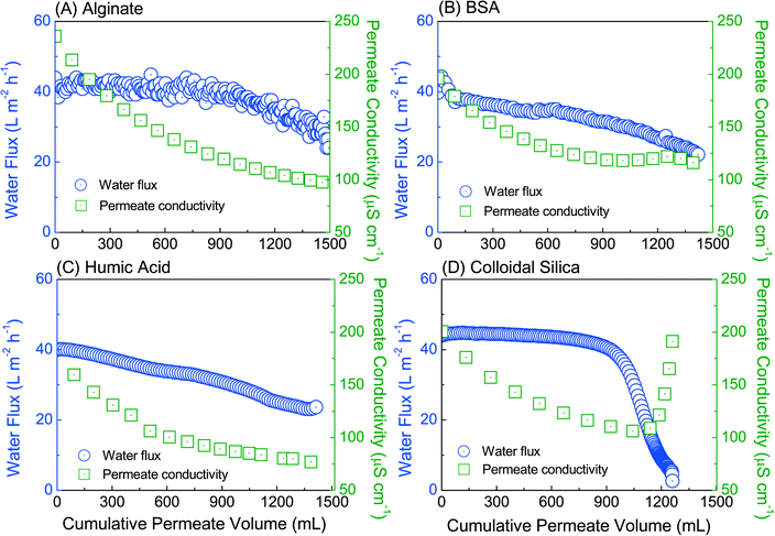
Unlike organic foulants, colloidal silica induced a severe water flux decline from 36 to 6 L m−2 h−1 at the cumulative permeate volume of 1000 mL (Fig. 1D); and concomitantly, a sharp increase in permeate conductivity indicated the undesirable wetting of the hydrophobic MD membrane, thereby compromising the product water quality. Such significant water flux decline was mainly driven by the deposition and aggregation of foulants onto membrane surface, rather than the concentration of feed NaCl solution that only led to a marginal decrease in water vapour pressure difference through the membrane. Due to the much smaller silica particle size than the MD membrane pore size, penetration of colloidal silica into the membrane pore first initiated pore wetting and intrusion,35 followed by internal pore blockage, thereby leading to severe water flux decline as well as deterioration of product water quality. Such detrimental membrane wetting was also evident by the significantly lower contact angle of colloidal silica fouled membrane (20 ± 2 °C) in comparison with that of alginate (81.9 ± 1.2 °C), humic acid (79.6 ± 2.2 °C) or BSA (78.6 ± 2.8 °C) fouled membranes (Fig. S2, ESI†). The MD membrane became hydrophilic after fouling with colloidal silica particles and presented a reduced liquid entry pressure, thereby enabling the transport of salt from the feed to the distillate stream through the membrane.
The ability to penetrate into and wet the MD membrane of the colloidal silica may significantly alter the fouling behaviour of combined foulants (colloidal silica with organic foulants), and warranted a closer examination of the fouling profile and the underlying mechanisms.
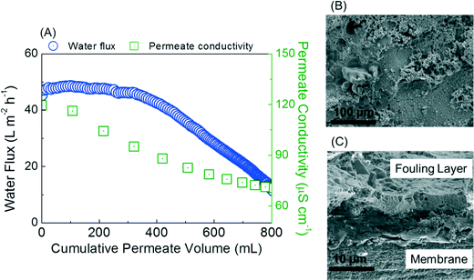
(a) Colloidal silica with alginate. Colloidal silica with alginate induced a severe water flux decline in comparison with alginate only (Fig. 1A). The water production was compromised, attaining only 800 mL permeate when more than 50% water flux decline was reached (Fig. 2A). However, no salt passage through the membrane (i.e., membrane wetting) was observed, which was evident from a continuous decrease in permeate conductivity.
The fouling layer morphology demonstrated a cake layer that compromised an alginate gel with clusters of colloidal aggregates (Fig. 2B and C). It is hypothesized that the gelation of viscous alginate formed a cage-like structure36 that can capture and trap colloidal silica, thereby minimizing the penetration of silica into membrane matrix as well as pore wetting.
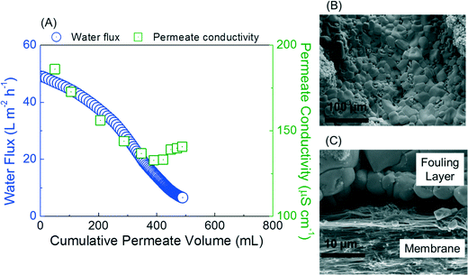
(b) Colloidal silica with BSA. Sharp water flux decline was demonstrated during the filtration of BSA with colloidal silica. Water flux decreased from 50 to 8 L m−2 h−1 within production of only 500 mL distillate (Fig. 3A), which was one third the production of filtering pure BSA (Fig. 1B). More alarming, a small but discernible increase in permeate conductivity was observed at the conclusion of the fouling, indicating the occurrence of partial pore wetting.
The cake layer induced by BSA with colloidal silica was distinctive in terms of the macromolecular stacking of globular BSA protein with a size of 1 μm with silica aggregates (Fig. 3B and C). The size of the BSA protein with silica aggregates was twice as large as the MD membrane pore and resulted in a severe pore blockage, thereby leading to dramatic water flux decline. BSA proteins tended to absorb onto the surface of colloidal silica and aggregate into large particles. Previous studies also showed that BSA protein was adsorbed by colloidal silica,33,37 which was evident by an increase of zeta potential from −10.3 to −5.7 mV between the BSA protein and colloidal particle (Fig. S4, ESI†). As a result, it is hypothesized that the silica–BSA interaction led to a significant increase in particle size via adsorption, and blocked the MD membrane pores, resulting in a severe loss in water production.
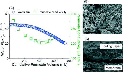
(c) Colloidal silica with humic acid. The water flux decline during processing feed with colloidal silica and humic acid was similar to that by colloidal silica with alginate. Only 800 mL permeate was collected when an approximately 50% water flux decline was achieved (Fig. 4A). However, a significant increase in permeate conductivity suggested detrimental membrane wetting (Fig. 4A). Humic acid became a compact coil under high ionic strength, and had negligible adsorption with colloidal silica,38 which was evident by the largely unchanged zeta potential (Fig. S2, ESI†). As a result, it is hypothesized that humic acid and colloidal silica deposited onto the membrane surface independently and formed the cake layer. Indeed, the fouling layer morphology showed the coiled humic acid was layered on top of colloidal silica (Fig. 4B and C). The colloidal silica cake layer adjacent to the membrane surface may partially wet the membrane pore, and enable the penetration of silica particles into the membrane matrix, thereby resulting in membrane wetting.
4. Quantifying synergistic fouling mechanisms
4.1 Colloidal silica–organic foulant interaction
We employed dynamic light scattering to track the change in foulant particle size during the MD fouling, and Fourier transform infrared (FTIR) spectroscopy to examine the chemical information at the membrane interface in a time-resolved manner. This information can index and capture the sequence of fouling layer development.Colloidal silica–organic foulant interaction in the feed solution was quantified by the changes of particle size (Fig. 5). Specifically, two clear peaks at 21 nm and 396 nm represented silica and alginate, respectively, at the beginning of filtration (Fig. 5A). The increase of intensity as well as particle size to 955 nm indicated the gelation of alginate from the cumulative permeate volume 200 mL to the completion of filtration. The BSA–colloidal silica interaction resulted in a swift particle size growth from 400 nm to 1.5 μm, which was consistent with severe water flux decline due to pore blockage (Fig. 5B). Humic acid and colloidal silica showed distinctive peaks as the particle size increased as filtration progressed (Fig. 5C), which indicated a relatively mild interaction and was consistent with less severe water flux decline.
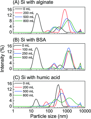 | ||
| Fig. 5 Feed solution particle size as a function of cumulative permeate volume during combined fouling in membrane distillation: (A) colloidal silica with alginate, (B) colloidal silica with BSA, and (C) colloidal silica with humic acid. Experimental conditions were described in Fig. 2–4. | ||
The FTIR spectra shed light on the deposition sequence of the foulants onto the membrane surface. For instance, as filtration progressed, the major peak increase was at wavenumber of 1634 cm−1 (C![[double bond, length as m-dash]](https://www.rsc.org/images/entities/char_e001.gif) O stretching),39,40 indicating the presence of alginate on the membrane surface (Fig. 6A). This observation was consistent with the hypothesis that alginate formed the cage-like structure and the alginate gel layers blocked the membrane pore during fouling. In the case of colloidal silica with BSA, the increase at the wavenumbers of 1642 cm−1 (C
O stretching),39,40 indicating the presence of alginate on the membrane surface (Fig. 6A). This observation was consistent with the hypothesis that alginate formed the cage-like structure and the alginate gel layers blocked the membrane pore during fouling. In the case of colloidal silica with BSA, the increase at the wavenumbers of 1642 cm−1 (C![[double bond, length as m-dash]](https://www.rsc.org/images/entities/char_e001.gif) O stretching), and 1055 cm−1 (Si
O stretching), and 1055 cm−1 (Si![[double bond, length as m-dash]](https://www.rsc.org/images/entities/char_e001.gif) O stretching) suggested the presence of protein as well as silica on the membrane surface (Fig. 6B). This chemical information agreed with the change in particle size, both of which demonstrated that the adsorption between colloidal silica and BSA led to an aggregate with a particle size over 1 μm, thereby resulting in severe water flux decline. The deposition of colloidal silica was earlier than that of humic acid onto the membrane because the occurrence of the Si
O stretching) suggested the presence of protein as well as silica on the membrane surface (Fig. 6B). This chemical information agreed with the change in particle size, both of which demonstrated that the adsorption between colloidal silica and BSA led to an aggregate with a particle size over 1 μm, thereby resulting in severe water flux decline. The deposition of colloidal silica was earlier than that of humic acid onto the membrane because the occurrence of the Si![[double bond, length as m-dash]](https://www.rsc.org/images/entities/char_e001.gif) O bond at wavenumber 1055 cm−1 (at a cumulative permeate volume of 500 mL) was prior to the appearance of the C
O bond at wavenumber 1055 cm−1 (at a cumulative permeate volume of 500 mL) was prior to the appearance of the C![[double bond, length as m-dash]](https://www.rsc.org/images/entities/char_e001.gif) O bond at wavenumber of 1642 cm−1 (at a cumulative permeate volume of 800 mL) (Fig. 6C). The progress of the FTIR spectra was consistent with the particle size growth, as well as the hypothesis that limited interaction occurred between humic acid and colloidal silica during the filtration.
O bond at wavenumber of 1642 cm−1 (at a cumulative permeate volume of 800 mL) (Fig. 6C). The progress of the FTIR spectra was consistent with the particle size growth, as well as the hypothesis that limited interaction occurred between humic acid and colloidal silica during the filtration.
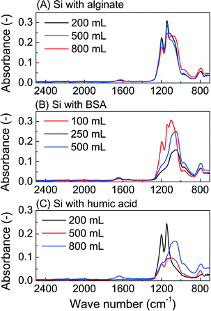 | ||
| Fig. 6 Fourier transform infrared spectra as a function of cumulative permeate volume of fouled membrane in membrane distillation by (A) colloidal silica with alginate, (B) colloidal silica with BSA, and (C) colloidal silica with humic acid. Experimental conditions were described in Fig. 2–4. | ||
4.2 Transport of colloidal silica into membrane pore
Membrane pore wetting and subsequent deterioration of product water was observed using combined foulants. The transport and penetration of colloidal particles through the membrane matrix can be the culprit for membrane wetting. We imaged and mapped the key elements of membrane cross section to demonstrate the spatial distribution of colloidal silica particles. The fluorine layer represented the active layer of the MD membrane, which was made of polytetrafluoroethylene. The oxygen and carbon elements enable the visualization of organic foulants. With these benchmarks, we can determine the location of silica in the fouling layer, and possible penetration of silica into the membrane.A close examination of the silicon element shed light on the mechanism of membrane wetting (Fig. 7). For instance, the fouling layer of colloidal silica with alginate showed a compact and continuous layer of silicon (Fig. 7A), without penetrating through the fluorine layer, which suggested that the majority of colloidal silica was rejected by the membrane. This result agreed well with the continuous decrease in permeate conductivity and further confirmed the hypothesis that the colloidal silica was trapped by the alginate gel, thereby blocking the membrane pore and inducing severe water flux decline.
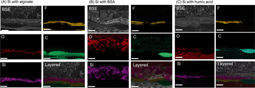 | ||
| Fig. 7 Element mapping by energy-dispersive X-ray spectroscopy of fouled membrane in membrane distillation by (A) colloidal silica with alginate, (B) colloidal silica with BSA, and (C) colloidal silica with humic acid, at the conclusion of experiment. Experimental conditions were described in Fig. 2–4. The back scattering electron (BSE) image was used for element mapping, and the distribution and relative location of key elements were presented in the layered image. Scale bar corresponds to 100 μm. | ||
In the case of colloidal silica with BSA, the silicon element mapping was aggravated by the BSA protein, resulting in a thick silicon element layer (Fig. 7B). More importantly, the silicon layer partially overlapped with the fluorine layer, which indicated the penetration of silica colloidal particles into the membrane matrix. Similarly, yet more severe silica penetration was observed in the case of colloidal silica with humic acid (Fig. 7C). The silicon element exhibited strong presence within membrane active layer, with some silica colloidal particles penetrating into the membrane. This observation indicated membrane wetting and agreed well with the significant increase in permeate conductivity. In addition, this element mapping further confirmed the hypothesis that the negligible interaction between colloidal silica and humic acid resulted in a layered structure with colloidal silica particles being deposited first onto the membrane, thereby facilitating pore wetting during the fouling.
Based on the aforementioned experimental observation, we can conceptually picture the fouling mechanisms of colloidal silica particles with varying organic foulants. Different mechanisms were presented in the combined fouling: (a) colloidal silica particles were trapped and caged by the gelation of alginate, thereby leading to a gel layer onto the membrane surface. Such interaction resulted in severe water flux decline, but did not compromise the product water quality because of the minimal penetration of silica into the membrane matrix; (b) colloidal silica particles adsorbed hydrophobic BSA protein, and resulted in a significant increase in particle size beyond 1 μm. Such aggregates partially blocked the membranes, and led to a swift water flux decline. Unbound silica particles also partially interacted with the membrane surface, and resulted in mild pore wetting; (c) humic acid, being a coiled structure in high salinity, showed limited interaction with colloidal silica particles. As a result, the colloidal silica particles penetrated into the membrane matrix and wetted the membrane pores, thereby compromising the product water quality.
4.3 Implications
The markedly different response of combined fouling with colloidal silica and varying organic foulants had significant implications for the management of MD processes in treating waste streams with a high fouling propensity. The interplay of colloidal silica particles with organic foulants during the filtration profoundly altered the MD performance and product water quality. The ability of colloidal silica particles to wet pores also provided guidance in the pre-treatment of feed streams, particularly the removal of particulate foulants prior to the MD process, in order to minimize membrane wetting, thereby maintaining the robustness and sustainability of the MD process.5. Conclusion
We examined mechanisms of synergistic effects of MD membrane fouling induced by three organic foulants – alginate, BSA and humic acid – in the presence of colloidal silica particles. Significantly different fouling profiles were observed in terms of water flux decline and product water quality. All combined fouling processes exhibited a more severe water flux decline in comparison with fouling by individual organic foulants. Gelation of alginate formed an alginate layer on the membrane surface and prevented the penetration of silica particles into the membrane matrix, which was confirmed by silicon element mapping as well as IR spectra. Adsorption of BSA protein by colloidal silica aggregates led to a sharp water flux decline and a partial pore wetting. Humic acid, forming a coil structure in high salinity, exhibited limited interaction with colloidal silica and colloidal silica penetrated into the membrane leading to membrane pore wetting, thereby compromising the product water quality.Acknowledgements
Authors would like to acknowledge the CSIRO Manufacturing for the financial support of this work. W. Qin would like to thank the scholarship from Zhejiang University via the Doctoral Student Exchange Program. M. Xie thanks the award of Vice Chancellor Early Career Researcher Fellowship from Victoria University. Assistant Professor Xiaosheng Ji from Zhejiang University is greatly acknowledged for helpful discussions. Ms Lee Russell and Mr Mark Greaves from CSIRO Manufacturing are thanked for their help with membrane characterisation.References
- A. Alkhudhiri, N. Darwish and N. Hilal, Desalination, 2012, 287, 2–18 CrossRef CAS.
- S. Adham, A. Hussain, J. M. Matar, R. Dores and A. Janson, Desalination, 2013, 314, 101–108 CrossRef CAS.
- X. Ji, E. Curcio, S. Al Obaidani, G. Di Profio, E. Fontananova and E. Drioli, Sep. Purif. Technol., 2010, 71, 76–82 CrossRef CAS.
- L. Mariah, C. A. Buckley, C. J. Brouckaert, E. Curcio, E. Drioli, D. Jaganyi and D. Ramjugernath, J. Membr. Sci., 2006, 280, 937 CrossRef CAS.
- C. R. Martinetti, A. E. Childress and T. Y. Cath, J. Membr. Sci., 2009, 331, 31–39 CrossRef CAS.
- H. C. Duong, A. R. Chivas, B. Nelemans, M. Duke, S. Gray, T. Y. Cath and L. D. Nghiem, Desalination, 2015, 366, 121–129 CrossRef CAS.
- H. C. Duong, S. Gray, M. Duke, T. Y. Cath and L. D. Nghiem, J. Membr. Sci., 2015, 493, 673–682 CrossRef CAS.
- A. Alkhudhiri, N. Darwish and N. Hilal, Desalination, 2013, 309, 46–51 CrossRef CAS.
- X.-M. Li, B. Zhao, Z. Wang, M. Xie, J. Song, L. D. Nghiem, T. He, C. Yang, C. Li and G. Chen, Water Sci. Technol., 2014, 69, 1036–1044 CrossRef CAS PubMed.
- D. L. Shaffer, L. H. Arias Chavez, M. Ben-Sasson, S. Romero-Vargas Castrillón, N. Y. Yip and M. Elimelech, Environ. Sci. Technol., 2013, 47, 9569–9583 CrossRef CAS PubMed.
- T. Y. Cath, D. Adams and A. E. Childress, J. Membr. Sci., 2005, 257, 111–119 CrossRef CAS.
- J. Phattaranawik, A. G. Fane, A. C. S. Pasquier and W. Bing, Desalination, 2008, 223, 386–395 CrossRef CAS.
- M. Xie, L. D. Nghiem, W. E. Price and M. Elimelech, Environ. Sci. Technol., 2013, 47, 13486–13493 CrossRef CAS PubMed.
- M. Xie, L. D. Nghiem, W. E. Price and M. Elimelech, Environ. Sci. Technol. Lett., 2014, 1, 191–195 CrossRef CAS.
- A. Hausmann, P. Sanciolo, T. Vasiljevic, M. Weeks, K. Schroën, S. Gray and M. Duke, J. Membr. Sci., 2013, 442, 149–159 CrossRef CAS.
- A. Hausmann, P. Sanciolo, T. Vasiljevic, M. Weeks, K. Schroën, S. Gray and M. Duke, J. Membr. Sci., 2013, 441, 102–111 CrossRef CAS.
- A. Zarebska, Á. C. Amor, K. Ciurkot, H. Karring, O. Thygesen, T. P. Andersen, M.-B. Hägg, K. V. Christensen and B. Norddahl, J. Membr. Sci., 2015, 484, 119–132 CrossRef CAS.
- Z. Wang, M. Elimelech and S. Lin, Environ. Sci. Technol., 2016, 50, 2132–2150 CrossRef CAS PubMed.
- Z. Wang, D. Hou and S. Lin, Environ. Sci. Technol., 2016, 50, 3866–3874 CrossRef CAS PubMed.
- L. D. Tijing, Y. C. Woo, J.-S. Choi, S. Lee, S.-H. Kim and H. K. Shon, J. Membr. Sci., 2015, 475, 215–244 CrossRef CAS.
- D. M. Warsinger, J. Swaminathan, E. Guillen-Burrieza, H. A. Arafat and J. H. Lienhard V, Desalination, 2015, 356, 294–313 CrossRef CAS.
- M. Xie, H. K. Shon, S. R. Gray and M. Elimelech, Water Res., 2016, 89, 210–221 CrossRef CAS PubMed.
- J. W. Chew, W. B. Krantz and A. G. Fane, J. Membr. Sci., 2014, 456, 66–76 CrossRef CAS.
- G. Naidu, S. Jeong, S.-J. Kim, I. S. Kim and S. Vigneswaran, Desalination, 2014, 347, 230–239 CrossRef CAS.
- Y. Z. Tan, J. W. Chew and W. B. Krantz, J. Membr. Sci., 2016, 504, 263–273 CrossRef CAS.
- A. M. Alklaibi and N. Lior, Desalination, 2005, 171, 111–131 CrossRef CAS.
- M. Gryta, K. Karakulski and A. W. Morawski, Water Res., 2001, 35, 3665–3669 CrossRef CAS PubMed.
- S. Lin, S. Nejati, C. Boo, Y. Hu, C. O. Osuji and M. Elimelech, Environ. Sci. Technol. Lett., 2014, 1, 443–447 CrossRef CAS.
- Y. Liao, R. Wang and A. G. Fane, J. Membr. Sci., 2013, 440, 77–87 CrossRef CAS.
- Y. Liao, R. Wang and A. G. Fane, Environ. Sci. Technol., 2014, 48, 6335–6341 CrossRef CAS PubMed.
- A. Razmjou, E. Arifin, G. Dong, J. Mansouri and V. Chen, J. Membr. Sci., 2012, 415–416, 850–863 CrossRef CAS.
- M. Schulz, A. Soltani, X. Zheng and M. Ernst, J. Membr. Sci., 2016, 507, 154–164 CrossRef CAS.
- Q. Li and M. Elimelech, J. Membr. Sci., 2006, 278, 72–82 CrossRef CAS.
- A. E. Contreras, A. Kim and Q. Li, J. Membr. Sci., 2009, 327, 87–95 CrossRef CAS.
- J. Gilron, Y. Ladizansky and E. Korin, Ind. Eng. Chem. Res., 2013, 52, 10521–10529 CrossRef CAS.
- H. Hecht and S. Srebnik, Biomacromolecules, 2016, 17, 2160–2167 CrossRef CAS PubMed.
- M. Wiśniewska, K. Szewczuk-Karpisz and D. Sternik, J. Therm. Anal. Calorim., 2015, 120, 1355–1364 CrossRef.
- C. Y. Tang, Y.-N. Kwon and J. O. Leckie, Environ. Sci. Technol., 2007, 41, 942–949 CrossRef CAS PubMed.
- M. Xie, C. Y. Tang and S. R. Gray, Desalination, 2016, 392, 85–90 CrossRef CAS.
- M. Xie and S. R. Gray, J. Membr. Sci., 2016, 513, 250–259 CrossRef CAS.
Footnote |
| † Electronic supplementary information (ESI) available. See DOI: 10.1039/c6ew00156d |
| This journal is © The Royal Society of Chemistry 2017 |

