Genesis of pure Se(0) nano- and micro-structures in wastewater with nanoscale zero-valent iron (nZVI)†
Xuefen
Xia
,
Lan
Ling
 * and
Wei-xian
Zhang
State Key Laboratory for Pollution Control and Resource Reuse, College of Environmental Science and Engineering, Tongji University, Shanghai, 200092 PR China. E-mail: linglan@tongji.edu.cn; Tel: +86 21 18501682197
First published on 26th September 2016
Abstract
Formation of pure elemental selenium has important implications in the separation, purification and recovery of selenium, a trace but vital and increasingly important industrial material. nZVI can quickly reduce both Se(VI) and Se(IV) to Se(0). Herein, we report highly efficient and rapid separation of selenium from wastewater and the discovery of distinctive nano- and micro-scale structures of pure selenium via the reduction of Se(IV) to Se(0) with nanoscale zero-valent iron (nZVI). Specifically, spherical and needle shaped Se(0) nanoparticles were observed under ambient conditions. Aqueous Se(IV) is first adsorbed to the nZVI surface, diffuses across the oxide layer and subsequently reduced to Se(0). The formed Se(0) particles were characterized using spherical aberration corrected scanning transmission electron microscopy (Cs-STEM) combined with energy dispersive spectroscopy (EDS), electron energy loss spectroscopy (EELS), scanning electron microscopy (SEM) and X-ray diffraction (XRD). XRD revealed that the Se(0) nanoparticles were pure hexagonal phase selenium crystals. EELS analysis provided additional and independent evidence on the Se(IV) reduction to Se(0). Selenium has long been discharged to the environment due to low efficiency of conventional technologies, and the discovery of pure Se(0) solids by nZVI reduction offers an innovative route for recovery of this valuable resource from wastewater.
Environmental significanceIn this work, we demonstrate that both selenate and selenite in wastewater can be reduced to pure elemental selenium and form novel nano- and micro-scale structures. This work provides valuable insights into the surface reactions of nZVI and also into the selenium nanochemistry. This work offers near atomic-resolution evidence on the Se–Fe reactions with the utilization of spherical aberration corrected scanning transmission electron microscopy (Cs-STEM) combined with energy dispersive spectroscopy (EDS) and electron energy loss spectroscopy (EELS). This is a truly sustainable and green nanotechnology for waste treatment as the value of recovered selenium can offset and even surpass the cost of wastewater treatment. The results may have important implications in the separation, purification and recovery of selenium. |
Introduction
Selenium (Se) is a metalloid with chemical properties between metals and nonmetals.1 Due to its unique semiconducting and photoactive properties, Se has found growing applications in photocopiers, electrical rectifiers, photographic exposure meters, microelectronic circuits, etc.2,3 On the other hand, Se is a trace element in the earth's crust (<0.05 mg kg−1). Total Se reserve in the world has been estimated at just 170![[thin space (1/6-em)]](https://www.rsc.org/images/entities/char_2009.gif) 000 tons.4 Tremendous efforts have been directed toward exploring Se-containing minerals and for efficient Se extraction and recycling.5,6
000 tons.4 Tremendous efforts have been directed toward exploring Se-containing minerals and for efficient Se extraction and recycling.5,6
Se is also an essential nutrient for human and other mammalians because of its anti-oxidation and anti-carcinogenic characteristics.7 On the other hand, Se at high dose (e.g. >400 μg per day) becomes acutely toxic8 and causes numbness in fingers and toes, hair and fingernail losses, and damage to kidney and liver tissue as well as nervous and circulatory systems.9
In short, Se is a valuable industrial material as well as a contaminant of concern. Thus, environmental discharges of Se from coal-fired power plants, coal mining and nonferrous metal smelting have received increasing regulatory attention.10–12 For example, the US Environmental Protection Agency (USEPA) has stipulated stringent standards on the discharge of selenium from wastewater. There is an urgent need for efficient and cost-effective technologies for Se removal, separation and recycling.
Se can exist as selenide [Se(−II)], elemental selenium [Se(0)], selenite [Se(IV)] and selenate [Se(VI)] in the environment.13 Oxyanions of Se(IV) and Se(VI) are the predominant species in natural waters. Se(IV) is more toxic, while Se(0) and Se(−II) are relatively immobile due to their low solubility in water. A common strategy for the removal of selenium, particularly Se(IV), from wastewater is to immobilize Se(IV) by reducing it to less or insoluble Se(−II) and/or Se(0).10,14
A variety of physical, chemical and biological methods have been suggested for selenium removal from wastewater.13,15–28 Microbial reduction of Se(IV) to Se(0) has been reported by many laboratory studies, and abiotic reduction of Se(IV) to Se(0) or Se(−II) by various iron-containing materials has also been documented. Nevertheless, existing methods are often slow and too expensive for the removal of trace level selenium.
Nanoscale zero-valent iron (nZVI) is a popular reducing agent used in groundwater remediation and hazardous waste treatment.29–32 Recently, nZVI has been suggested as a potential agent for Se reduction and separation from contaminated water.10,29 For example, the removal rate of Se(VI) by zero-valent iron nanoparticles was observed to be much higher than conventional Fe(0) powder.10 In our previous work,29 reaction mechanisms of Se(IV) in a single nZVI particle were elucidated. It was demonstrated that Se(IV) is reduced to Se(−II) and Se(0) at the iron oxide–Fe(0) interface. Since Se(0) has little or no toxicity14,33 and can be easily removed from the aqueous phase, this method thus has potential applications in the separation, purification and recovery of selenium. Preliminary experiments showed that Se(IV) removal efficiency of nZVI was 3.3–11 times higher than those of other common materials such as Fe3O4, Fe2O3, micro-scale iron, Fe(OH)3, TiO2, Al2O3, and activated Al2O3 (Fig. S1 and Table S1, ESI†). Nonetheless, current understanding on the chemical composition and structural properties of the formed Se(0) is still limited, especially on the mechanisms of Se recovery and reuse.
The primary objective of this work was to characterize the end products of the Se(IV)–Fe(0) reactions and to obtain direct evidence of the Se(0) nano/microstructures. The morphology and structure of the formed Se(0) nanoparticles were studied by using state-of-the-art microscopy and X-ray techniques. We examined the Se(0) structures by spherical aberration corrected scanning transmission electron microscopy (Cs-STEM) integrated with energy-dispersive X-ray spectrometry (EDS) and electron energy loss spectroscopy (EELS) and probed the crystalline structure and composition by X-ray diffraction (XRD). The results further clarified the formation mechanisms of Se(0) in the reactions of Se(IV) with nZVI and also demonstrated the potential of nZVI for efficient separation and recovery of selenium from wastewater.
Experimental
Chemicals and materials
All reagents used (e.g. FeCl3·6H2O, NaBH4, Na2SeO3, HCl, NaOH, HNO3, α-Fe2O3) were of analytical grade or higher, and all were obtained from Sigma-Aldrich and used without any further purification. Stock solutions (1000 mg L−1) of Na2SeO3 were prepared in deionized (DI) water, and precise dilutions were made immediately before use.Preparation of iron nanoparticles
The iron nanoparticles used in this work were prepared by the reduction of ferric chloride with sodium borohydride following the procedures published previously.34 The synthesized nanoparticles were collected and washed with deionized (DI) water and anhydrous ethanol (>99.8%). Fresh nZVI was stored in anhydrous ethanol in sealed polyethylene containers at 4 °C until use. The average size of nZVI was approximately 60 nm, and the BET surface area was in the range of 25–35 m2 g−1.Batch experiments
Batch experiments were carried out in 50 mL serum bottles, with 0.2–1.5 g L−1 nZVI added to 35 mL of 0.1–580 mg L−1 Se(IV) solution. The batch bottles were sealed with screw caps and mixed on a shaker table (180 rpm) at room temperature (ca. 22 °C). To eliminate the potential effect of dissolved oxygen (DO), the Se(IV) solutions were purged with high-purity nitrogen (>99.9%) for 30 minutes prior to the introduction of nZVI. Solution pH was adjusted by adding 0.1 M HCl or NaOH at the start of experiments. At given time intervals, the bottles were removed from the shaker table. The suspensions were filtered through 0.22 μm pore size membrane filters. The filtrates were subsequently acidified with HNO3. An Agilent 720ES ICP was used to measure Se concentration in the solution, which has a detection limit of <4 ppb. The spent nZVI particles were collected on the membrane filters, rinsed twice with anhydrous ethanol, and then stored in a nitrogen glovebox before STEM microscopy, SEM, XRD and EELS characterization. The comparison experiments between nZVI and pure hematite particles (α-Fe2O3, 50 nm) for Se(IV) removal at different solution pH was conducted at a dosage of 0.5 g L−1 and a Se(IV) concentration of 120 mg L−1, with a contact time of 24 h. All experiments were performed in duplicate or triplicate.Analytical methods
Iron nanoparticles were characterized by independent techniques including X-ray diffraction (XRD), scanning electron microscopy (SEM) and spherical aberration corrected scanning transmission electron microscopy integrated with X-ray energy-dispersive spectroscopy (Cs-STEM-EDS) and electron energy loss spectroscopy (Cs-STEM-EELS).A FEI Titan™ G2 60-300 Cs-STEM was operated at 200 kV to perform the morphological, structural and elemental characterization on the Se(IV) reactions in nZVI. This instrument is equipped with a high brightness Schottky field emission source (brightness of 1.8 × 10⁹ A cm−2 srad−1 at 200 kV, beam current of 1300 pA in 0.2 nm spot), high-angle annular dark-field (HAADF) and bright-field (BF) detectors, an electron energy loss spectrometer (EELS) (Gatan, USA), and a ChemiSTEM™ system. To minimize the effects of specimen drift, a drift-correction mode was applied during the acquisition of EDS maps. Deconvolution was applied to remove the effect of plural scattering in the EELS spectrum. Samples for analysis were prepared by depositing a drop of sample dispersed in anhydrous ethanol on a lacey carbon film supported on a copper grid in a nitrogen-filled glovebox. More details on the Cs-STEM methods can be found elsewhere.29,35,36
XRD analysis was carried out using a Bruker D8 Advance X-ray diffractometer at 40 kV and 40 mA with graphite-monochromated Cu Kα radiation. The XRD patterns were collected in the 2ϑ range of 10–90° at the rate of 2° min−1. This scan range covers major species of interests in this work, i.e. Fe, O and Se.
Results and discussion
Removal of Se(IV) from water
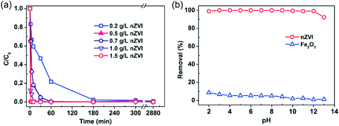
As shown in Fig. 1 (more data are provided in the ESI,† Fig. S2), rapid removal of Se(IV) from water can be achieved even at high levels of Se(IV) (e.g. at 580 mg L−1). Fig. 1a presents the effect of nZVI dosage (0.2 to 1.5 g L−1) on Se(IV) removal. In general, the removal rate rises with increasing nZVI dosage. For example, almost 99.6% of Se(IV) was removed in less than 1 min using 1.5 g L−1 nZVI. When the nZVI dosage was in the range of 0.5–0.7 g L−1, 99.5% of Se(IV) was removed in about 60 min. With 0.2 g L−1 nZVI, it took about 300 min to achieve similar removal efficiency.Experiments with solution pH from 2.0 to 13.0 found no apparent pH impact on the Se(IV) removal efficiency after 24 h reactions with nZVI (Fig. 1b). In comparison, the Se(IV) removal efficiency with iron oxide (hematite, α-Fe2O3, 50 nm) was much lower and gradually decreased with increasing pH (Fig. 1b). Se(IV) can be removed by adsorption followed with reduction to Se(0) and Se(−II).29 Meanwhile, Se(IV) removal by iron oxides such as Fe2O3 is by surface sorption, which is highly dependent on the solution pH.37,38 As shown in Fig. 1b, the maximum removal efficiency by Fe2O3 was merely 8.7% at pH 2.0. When the solution pH was above 9.0, little removal of Se(IV) was observed. Fig. 1b also shows that, in comparison with Fe2O3, a small dose of nZVI is capable of removing Se(IV) within a wide pH range. Normalizing to 1 g of nZVI, the removal capacity was estimated to be 240 mg of Se(IV) per gram of Fe0.
Microscopic observations
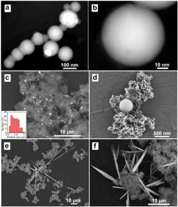
Micrographs were obtained to analyze the morphological and structural evolution of nZVI after reactions with Se(IV). Fresh nZVI particles were spherical in shape with sizes ranging from 20 to 100 nm and often presented as chain-like aggregates due to magnetic attractions, colloidal aggregation and the formation of a continuous layer of iron hydroxide on the surface (Fig. 2a).35 Each individual nanoparticle is composed of a metallic iron core and separated from each other by a thin (∼2–4 nm) interfacial iron oxide layer (Fig. 2b). High angle annular dark field (HAADF) images showed that the particle consisted of a bright core, corresponding to the metallic iron, while the outer layer appeared dim due to the presence of lower-atomic-weight oxygen atoms.35,39 The core–shell configuration bestowed the nanoparticles the reductive character of metallic iron as well as adsorptive and coordinative properties of iron oxides in water.After reactions with Se(IV), nZVI was extensively oxidized with a few particles maintaining the original spherical shape. More importantly, microscopic examinations revealed the formation of new structures with heterogeneous shapes and sizes. Specifically, we observed two major types of nanostructures: spherical and needle-shaped Se nanoparticles (Fig. 2–4). Spherical shapes with sizes ranging from a few nanometers to about a few micrometers were observed (Fig. 2c) and were broadly distributed in the spent nZVI. High-magnification SEM images (Fig. 2d) clearly revealed that the nanospheres had a dense structure and a smooth surface. As shown in Fig. 2e and f, numerous needle-shaped nanoparticles were also formed after the reactions, which had the width or dimension of less than 100 nm and the lengths increasing with time to a few micrometers.
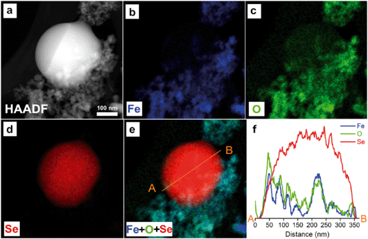
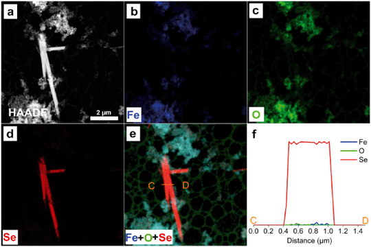
To further characterize the elemental compositions of the newly formed nanostructures, EDS mapping on the reacted nZVI particles was performed. Fig. 3 and 4 present HAADF images, STEM-EDS elemental mappings of Fe (Kα), O (Kα) and Se (Lα), color overlays of the three elements, and also elemental line profiles. Fe, Se and O are shown in blue, red and green, respectively.
As shown in Fig. 3a, a near-perfect nanosphere with a diameter of 325 nm was observed using the HAADF detector. This nanosphere was much bigger and denser than fresh nZVI. Out of the three major elements in the system, Fe, O and Se, Se has the greatest atomic number of 34, O = 8 and Fe = 26, thus it is expectedly brighter than the surrounding area in the HAADF image. Fe and O mappings (Fig. 3b and c) showed the footprints of iron and oxygen, respectively. Fig. 3e is a color overlay of the three elements. This image clearly illustrated the spatial distribution of each element in the specimen. A spherical particle of nearly pure Se was formed. The Fe and O were present mostly in the background likely in the form of iron corrosion products, suggesting the lack of specific chemical bonding between Se and Fe. This observation indicates that the Se nanosphere can grow outside the nZVI.
Relative abundance of Fe, O, and Se across this newly formed structure was quantified with a line scanning profile (Fig. 3f). The white straight line crossing the nanosphere region in the overlay image (Fig. 3e) showed the trajectory of the line scan. Distribution of Se along the white line further showed a pure spherical Se structure with a corresponding bell-shaped Se profile. Only trace amounts of Fe and O were found in the particle center.
As shown in Fig. 4a, nano-needles were also observed. The needle-shaped formations increased rapidly, while the spherical Se particles diminished with the progress of reaction time. The EDS Se mapping (Fig. 4d) and EDS line profiles over the nano-needles (Fig. 4f) confirmed that they were also of pure Se, similar to the results of spheres presented in Fig. 3. The chemical compositions of nanospheres and nano-needles were further verified by EDS quantitative analysis (Fig. S3 and S4†). The quantitative analysis confirmed that the Se nanostructures are mostly composed of Se with little Fe or O.
The new Se structures observed in this work were assigned to two well-known allotropes of elemental selenium. The nanospheres were amorphous selenium (a-Se), while the nano-needles were grey trigonal selenium (t-Se).
Thermodynamically, a-Se is unstable due to its higher free energy relative to that of the t-Se and spontaneously evolves to the crystalline nanostructures of t-Se. In other words, the a-Se nanospheres are intermediates in the reactions toward the final formation of t-Se needles.40 According to the Ostwald ripening mechanism,41 small Se(0) nanoparticles could grow into larger ones, which likely resulted in the poor size distribution of the a-Se nanospheres shown in Fig. 2.
The Se(0) nanospheres and nanoneedles can be obtained on a large scale under various environmental conditions. This has been confirmed through a series of batch experiments with respect to reaction time, initial Se(IV) concentration, nZVI dosage, initial pH, and temperature. In these experiments, no effort was made to minimize contact with the atmospheric oxygen. SEM images of spent nZVI particles are shown in Fig. S5–S9.† In general, the effect of environmental conditions on the formation of Se(0) nanoparticles is negligible.
XRD analysis
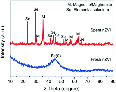
XRD analysis clearly identified peaks corresponding to body-centered cubic (bcc) α-Fe(0), with a strong peak at 44.9° ascribable to the (110) plane from the fresh nZVI sample. The non-Lorentzian shape of these peaks suggests a distribution of crystallite dimensions. The broad iron peak implies that the fresh nZVI particles possess an amorphous structure (Fig. 5). This result is similar to the findings of the previous studies.32,39From the spent nZVI sample, diffraction peaks at 2ϑ = 23.5, 29.7, 41.3, 43.6, 45.4, 51.7 and 65.2° were from the (100), (101), (110), (102), (111), (201) and (210) reflections of the pure hexagonal phase of selenium crystals (JCPDS 06-0362). These strong and sharp reflection peaks could be indexed to the trigonal Se with the p3121 space group and could be attributed to the presence of the t-Se nanostructure.
After reactions, peaks at 30.1, 35.4, 43.1, 53.4, 56.9, and 62.5° in 2ϑ matched the magnetite and/or maghemite pattern. Magnetite and maghemite in the nanoparticles could not be distinguished definitely by the XRD patterns as both are isomorphous and have similar lattice parameters.42 It should be noted that both magnetite and maghemite have magnetic properties as well as nZVI, which suggests that the spent nZVI could be effectively separated from solution with a permanent magnet and offers an efficient technique for the recovery of elemental selenium.
EELS analysis
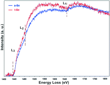
Another independent technique, the EELS analysis, was performed to characterize the fine structural features of the formed Se particles (Fig. 6). The selenium L electron energy loss (EEL) edges at 1436 eV (L3), 1476 eV (L2) and 1654 eV (L1) resulting from the ionization of the Se shell by the primary electrons were used for Se identification. It should be noted that the Fe M2,3 edge at 54 eV and the Se M4,5 edge at 57 eV are very close so that separation and positive identification by the EELS detector is difficult to achieve on this Cs-STEM.Background-subtracted EEL spectra of a-Se (assigned blue) and t-Se (assigned red) in spent nZVI are shown in Fig. 6. Se L3 and L2, located at ∼1436 eV and ∼1476 eV, respectively, were delayed maximum step-like edges. It is apparent that a-Se and t-Se in spent nZVI had similar L3, L2 edge onset, but t-Se had higher slopes. a-Se and t-Se had a similar L1 edge position at ∼1654 eV with minor abrupt onset. Overall, the EEL spectra of a-Se and t-Se particles had the same L3, L2, L1 edge positions as those found in the Se EELS atlas, thus confirming the reduction of Se(IV) to Se(0). The fine structure differences provided independent confirmation on the valence state of Se, the interatomic distance between the selenium atoms, the nature of the Se–Se bond, and also the coordination state and number.43,44
Mechanisms on the formation of Se(0) nano/microstructures
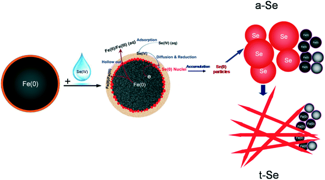
As demonstrated in this work and also in previous studies,29,35,36,45 nZVI has a classic core–shell structure (Fig. 7). Specifically, it contains a metallic iron core encapsulated with a layer of iron hydroxides (FeOOH).32,36,39,46 The iron oxide shell in water gains surface acid–base functions and provides surface sites for the electrostatic attraction and sorption of Se(IV), whereas the metallic iron in the core area serves as an electron source and exerts a reducing character, responsible for the observed reduction of Se(IV) to Se(0) and Se(−II).The dissolved Se(IV) is first attracted to the nZVI surface, forming inner-sphere monodentate/bidentate surface Se complexes.22,47,48 This step is relatively fast due to the small size and large surface area of nZVI and the polar or charged iron oxide shell.22 Further penetration or diffusion across the oxide layer is accelerated by its chemical reduction mediated by Fe(0), and the reduced products [i.e. Se(−II) and Se(0)] deposit and accumulate at the oxide/Fe(0) interface. Meanwhile, the metallic iron is oxidized and partially dissolved to form iron (hydr)oxides. Considering the relatively high concentration of the initial selenite in this experiment, Se(IV) was reduced, cumulatively enriched and evolved to Se nuclei.
The Se nuclei continue to grow with time into larger structures via the accumulation of newly reduced Se and by the Ostwald ripening mechanism.40,41 Due to their higher free energies compared to t-Se structures, the nanospheres slowly dissolve and reprecipitate as t-Se nanocrystallines.49 The t-Se nanocrystals then serve as the new seeds to attract Se atoms and form the t-Se nanostructure. This spontaneous process continues until all a-Se colloids are depleted in the solution, leaving behind a pure t-Se phase. The morphology of t-Se is strongly dependent on the amounts of both a-Se colloids and t-Se seeds.50 The elemental Se nuclei could be further reduced to Se(−II) and form a thin Se layer.29 A conceptual model highlighting the evidence observed in this work on the reduction of Se(IV) and formation of Se(0) nano/microstructures is illustrated in Fig. 7.
We are in the process of applying this nZVI technology for large-scale (∼50–100 kg Se per day) recovery of selenium in a wastewater treatment plant at a metal-smelting factory. This wastewater contains a relatively high level of dissolved selenium (>100 mg Se L−1). Preliminary results suggest that over 80–90% of Se can be quickly separated from the wastewater and the value of recovered selenium can offset most and even surpass the cost of wastewater treatment (∼$8–10 m−3). This nZVI technology has shown the promise as a truly sustainable and green nanotechnology for waste treatment.
Conclusions
In summary, Se(IV) can be rapidly separated from aqueous media and reduced to Se(0) by nZVI. Microscopic observations provided direct evidence on the formation of Se(0) nano/microstructures. Cs-STEM-EDS, SEM, XRD and EELS analyses proved that the pure elemental Se nanostructures can be generated under ambient temperature and pressure. Magnetite and/or maghemite were the end products of nZVI oxidation. Due to the magnetic properties of magnetite/maghemite, the spent nZVI could be easily separated from water, and thus, the pure Se(0) nanoparticles could be conveniently recovered.Acknowledgements
Financial support from the National Natural Science Foundation of China (NSFC Grants 21307094 and 21277102) and the Collaborative Innovation Center for Regional Environmental Quality is acknowledged.Notes and references
- A. C. Scheinost, R. Kirsch, D. Banerjee, A. Fernandez-Martinez, H. Zaenker, H. Funke and L. Charlet, J. Contam. Hydrol., 2008, 102, 228–245 CrossRef CAS PubMed.
- R. S. Oremland, M. J. Herbel, J. S. Blum, S. Langley, T. J. Beveridge, P. M. Ajayan, T. Sutto, A. V. Ellis and S. Curran, Appl. Environ. Microbiol., 2004, 70, 52–60 CrossRef CAS PubMed.
- V. V. Poborchii, A. V. Kolobov and K. Tanaka, Appl. Phys. Lett., 1999, 74, 215–217 CrossRef CAS.
- W. Butterman and R. Brown Jr, Mineral Commodity Profiles: Selenium, Report 2331-1258, 2004 Search PubMed.
- L. C. Staicu, E. D. van Hullebusch and P. N. Lens, Environ. Chem. Lett., 2015, 13, 89–96 CrossRef CAS.
- R. X. Zhou, J.-H. Zhao and Z.-M. Wei, Chem. Eng. J., 2012, 191, 386–393 CrossRef CAS.
- D. R. Ellis and D. E. Salt, Curr. Opin. Plant Biol., 2003, 6, 273–279 CrossRef CAS PubMed.
- L. H. Winkel, C. A. Johnson, M. Lenz, T. Grundl, O. X. Leupin, M. Amini and L. Charlet, Environ. Sci. Technol., 2011, 46, 571–579 CrossRef PubMed.
- Y. Fu, J. Wang, Q. Liu and H. Zeng, Carbon, 2014, 77, 710–721 CrossRef CAS.
- J. T. Olegario, N. Yee, M. Miller, J. Sczepaniak and B. Manning, J. Nanopart. Res., 2010, 12, 2057–2068 CrossRef CAS.
- S. Q. Liu, Y. T. Wang, L. Yu and J. Oakey, Fuel, 2006, 85, 1550–1558 CrossRef CAS.
- A. D. Lemly, Ecotoxicol. Environ. Saf., 2004, 59, 44–56 CrossRef CAS PubMed.
- A. C. Scheinost and L. Charlet, Environ. Sci. Technol., 2008, 42, 1984–1989 CrossRef CAS PubMed.
- Y. W. Chen, L. Li, A. D'Ulivo and N. Belzile, Anal. Chim. Acta, 2006, 577, 126–133 CrossRef CAS PubMed.
- C. Garbisu, T. Ishii, T. Leighton and B. B. Buchanan, Chem. Geol., 1996, 132, 199–204 CrossRef CAS.
- S. L. Hockin and G. M. Gadd, Appl. Environ. Microbiol., 2003, 69, 7063–7072 CrossRef CAS PubMed.
- E. Breynaert, C. Bruggeman and A. Maes, Environ. Sci. Technol., 2008, 42, 3595–3601 CrossRef CAS PubMed.
- L. Charlet, A. C. Scheinost, C. Tournassat, J. M. Greneche, A. Gehin, A. Fernandez-Martinez, S. Coudert, D. Tisserand and J. Brendle, Geochim. Cosmochim. Acta, 2007, 71, 5731–5749 CrossRef CAS.
- L. Liang, W. Yang, X. Guan, J. Li, Z. Xu, J. Wu, Y. Huang and X. Zhang, Water Res., 2013, 47, 5846–5855 CrossRef CAS PubMed.
- A. M. Scheidegger, D. Grolimund, D. Cui, J. Devoy, K. Spahiu, P. Wersin, I. Bonhoure and M. Janousch, J. Phys. IV, 2003, 104, 417–420 CAS.
- R. López de Arroyabe Loyo, S. I. Nikitenko, A. C. Scheinost and M. Simonoff, Environ. Sci. Technol., 2008, 42, 2451–2456 CrossRef.
- S. C. B. Myneni, T. K. Tokunaga and G. E. Brown, Science, 1997, 278, 1106–1109 CrossRef CAS.
- P. Refait, L. Simon and J. M. R. Genin, Environ. Sci. Technol., 2000, 34, 819–825 CrossRef CAS.
- A. Puranen, M. Jonsson, R. Dahn and D. Cui, J. Nucl. Mater., 2010, 406, 230–237 CrossRef CAS.
- J. S. Yamani, A. W. Lounsbury and J. B. Zimmerman, Water Res., 2016, 88, 889–896 CrossRef CAS PubMed.
- P. Dessì, R. Jain, S. Singh, M. Seder-Colomina, E. D. van Hullebusch, E. R. Rene, S. Z. Ahammad, A. Carucci and P. N. Lens, Water Res., 2016, 94, 146–154 CrossRef PubMed.
- C. Tang, Y. H. Huang, H. Zeng and Z. Zhang, Water Res., 2014, 67, 166–174 CrossRef CAS PubMed.
- J. Chung, R. Nerenberg and B. E. Rittmann, Environ. Sci. Technol., 2006, 40, 1664–1671 CrossRef CAS PubMed.
- L. Ling, B. Pan and W. X. Zhang, Water Res., 2015, 71, 274–281 CrossRef CAS PubMed.
- S. Bang, M. D. Johnson, G. P. Korfiatis and X. Meng, Water Res., 2005, 39, 763–770 CrossRef CAS PubMed.
- Z. Shi, J. T. Nurmi and P. G. Tratnyek, Environ. Sci. Technol., 2011, 45, 1586–1592 CrossRef CAS PubMed.
- W. Yan, R. Vasic, A. I. Frenkel and B. E. Koel, Environ. Sci. Technol., 2012, 46, 7018–7026 CrossRef CAS PubMed.
- R. Dungan and W. Frankenberger, Biorem. J., 1999, 3, 171–188 CrossRef CAS.
- X. Q. Li and W. X. Zhang, Langmuir, 2006, 22, 4638–4642 CrossRef CAS PubMed.
- L. Ling and W. X. Zhang, J. Am. Chem. Soc., 2015, 137, 2788–2791 CrossRef CAS PubMed.
- L. Ling and W. X. Zhang, Environ. Sci. Technol. Lett., 2014, 1, 305–309 CrossRef CAS.
- M. Rovira, J. Giménez, M. Martínez, X. Martínez-Lladó, J. de Pablo, V. Marti and L. Duro, J. Hazard. Mater., 2008, 150, 279–284 CrossRef CAS PubMed.
- D. Peak and D. Sparks, Environ. Sci. Technol., 2002, 36, 1460–1466 CrossRef CAS PubMed.
- C. Wang, D. R. Baer, J. E. Amonette, M. H. Engelhard, J. Antony and Y. Qiang, J. Am. Chem. Soc., 2009, 131, 8824–8832 CrossRef CAS PubMed.
- B. Gates, B. Mayers, A. Grossman and Y. Xia, Adv. Mater., 2002, 14, 1749–1752 CrossRef CAS.
- U. Jeong and Y. Xia, Adv. Mater., 2005, 17, 102–106 CrossRef CAS.
- Q. Wang, S. Snyder, J. Kim and H. Choi, Environ. Sci. Technol., 2009, 43, 3292–3299 CrossRef CAS PubMed.
- S. C. Lee, J. D. Benck, C. Tsai, J. Park, A. L. Koh, F. Abild-Pedersen, T. F. Jaramillo and R. Sinclair, ACS Nano, 2015, 10, 624–632 CrossRef PubMed.
- Y. J. Kim, R. Tao, R. F. Klie and D. N. Seidman, ACS Nano, 2012, 7, 732–739 CrossRef PubMed.
- X. Li and W. Zhang, J. Phys. Chem. C, 2007, 111, 6939–6946 CAS.
- Q. Wang, S. Lee and H. Choi, J. Phys. Chem. C, 2010, 114, 2027–2033 CAS.
- M. Duc, G. Lefevre, M. Fedoroff, J. Jeanjean, J. Rouchaud, F. Monteil-Rivera, J. Dumonceau and S. Milonjic, J. Environ. Radioact., 2003, 70, 61–72 CrossRef CAS PubMed.
- K. F. Hayes, A. L. Roe, G. E. Brown, K. O. Hodgson, J. O. Leckie and G. A. Parks, Science, 1987, 238, 783–786 CAS.
- B. Gates, Y. D. Yin and Y. N. Xia, J. Am. Chem. Soc., 2000, 122, 12582–12583 CrossRef CAS.
- Z. Quan, P. Yang, C. Li, X. Zhang, J. Yang and J. Lin, Cryst. Growth Des., 2008, 8, 3834–3839 CAS.
Footnote |
| † Electronic supplementary information (ESI) available: Fig. S1–S9 and Table S1. See DOI: 10.1039/c6en00231e |
| This journal is © The Royal Society of Chemistry 2017 |

