
 Open Access Article
 This Open Access Article is licensed under a Creative Commons Attribution-Non Commercial 3.0 Unported Licence
Preparation of high oxygen storage capacity and thermally stable ceria–zirconia solid solution
Jie
Li
,
Xiaofei
Liu
,
Wangcheng
Zhan
,
Yun
Guo
,
Yanglong
Guo
and
Guanzhong
Lu
*
Key Laboratory for Advanced Materials and Research Institute of Industrial Catalysis, East China University of Science and Technology, Shanghai, 200237, PR China. E-mail: gzhlu@ecust.edu.cn; Fax: +86 21 64252923
First published on 9th November 2015
Abstract
Ceria–zirconia solid solution is a very important material in three-way catalysts for automotive emission control. High oxygen storage capacity (OSC) and thermally stable Ce0.5Zr0.5O2 was prepared by a modified complexing–coprecipitation (CC) method, and its surface area reached 44 m2 g−1 after calcination at 1100 °C for 6 h. Based on the characterizations of its structural and physicochemical properties, it was found that Ce0.5Zr0.5O2 prepared by the CC method existed as the t′′-phase with rich oxygen defects and surface Ce3+ and has a larger BET surface area, uniform particle and pore sizes, and excellent bulk oxygen migration and redox abilities than samples prepared by other methods. After being calcined at 1100 °C for 6 h, its surface area, OSC (and OSCC, oxygen storage capacity complete) and catalytic activity for the oxidation of CO were still the best among three Ce0.5Zr0.5O2 solid solutions prepared by three methods whether it was used as the catalyst or as a support for a Pd catalyst, reflecting its good thermostability, although its particle and pore sizes were somewhat increased. This complexing–coprecipitation method can be used to prepare other high surface area and thermally stable inorganic materials.
1. Introduction
Ceria–zirconia solid solution (CZSS) has attracted more interest recently due to its extensive applications in catalytic processes.1–13 As an oxygen storage material CZSS has been used in three-way catalysts (TWCs) for the catalytic purification of CO, NOx and hydrocarbons (HCs) from automobile exhausts, and the presence of CZSS can enlarge the stoichiometric window of air-to-fuel ratio in TWCs by the help of its outstanding redox ability, in other words, its excellent oxygen storage/release capacity.14–17 In the CZSS, oxygen storage/release circularly occurs through the Ce4+/Ce3+ redox couple (CeO2 ↔ CeO2−x + (x/2) O2; x = 0–0.5).18 However, pure ceria is not very usable because of its relatively low OSC (oxygen storage capacity) and poor thermal stability,19,20 and the incorporation of ZrO2 (Zr4+) into the ceria lattice significantly affects ceria performance by enhancing the thermal resistance, thus increasing the OSC.1,21 Many research works were focused on the composition of CZSS and the preparation methods in order to obtain a high oxygen storage capacity and thermally stable CZSS.22 Our research results based on DFT + U calculations for the formation of O vacancies in a series of Ce1−xZrxO2 materials show that the formation energy of the O vacancy is dependent on the bond energy (Ebond) and relaxation energy (Erelax), and Ce0.5Zr0.5O2 possesses the lowest formation energy of the O vacancy.23With the increasingly strict regulations requiring lower emission standards of automotive vehicles, the catalytic performance of three-way catalysts should be further improved. Therefore, the oxygen storage/release ability and thermal stability of CZSS materials must be improved. Many research groups have already prepared CZSS by different methods using various ceria-based materials, and CZSS with various degrees of homogeneity and crystal and textual properties were reported.24 The reported preparation methods include coprecipitation,25,26 hydrothermal process,27,48 sol–gel means28–31 and other auxiliary methods, such as supercritical, surfactant and shape-controlled techniques.32–34 In addition, other rare earth elements are also doped into CZSS to enhance its structural and physiochemical properties.35–40 The CZSS prepared by Raju et al.41 has a surface area of ∼12 m2 g−1 after calcination at 1000 °C by continuous hydrothermal treatment, and the highest OSC of the Ce0.5Zr0.5O2 solid solution reached 0.58 mmol[O] g−1 after calcination at 700 °C. Wang et al.36 studied the effect of La doping into CZSS and found that the presence of doped La can enhance its BET surface area and OSC value. An analogous conclusion was reported by Yan et al.42 These results show that the aliovalent substitution of trivalent ions is deemed to stabilize the t′′ structure, which is believed to improve the thermal stability and OSC. Furthermore, Letichevsky et al. studied the effect of synthesis conditions on the properties of CZSS and found that cerium precursor has the most significant influence on the preparation procedure, and the positive function of controlling the pH cannot be neglected.25 Nevertheless, the oxygen storage capacity and thermal stability of CZSS materials should be further improved, and κ-Ce2Zr2O8 CZSS has not been synthesized successfully, which has an outstanding OSC compared with ordinary or commercial CZSS materials as verified by our DFT calculation.43
Herein, we selected the Ce0.5Zr0.5O2 solid solution as the model compound because of its higher oxygen mobility and thermal stability41,44–46 and tried to design a new synthesis method (the complexing–coprecipitation, CC method) combined with controlling the pH value of the mixed precursor solution to realize the preparation of CZSSs with high oxygen storage capacity and thermal stability. Their physicochemical and redox properties and catalytic activity for CO oxidation were investigated and compared with those of ordinary CZSSs prepared by the coprecipitation (CP) method, and the relationship between the preparation method – structure (including thermal stability) – and physicochemical properties (including oxygen storage capacity and catalytic performance) has been discussed in detail.
2. Experimental section
2.1. Preparation of sample
Ce0.5Zr0.5O2 solid solution was prepared by three methods.Finally, three samples were calcined in static air at 500 °C for 4 h. The obtained fresh samples were denoted as CZ-1, CZ-2, and CZ-3. The fresh samples were further calcined at 1100 °C for 6 h in dry air to obtain the aged samples (CZ-1a, CZ-2a, and CZ-3a).
2.2. Preparation of Pd/CZ catalysts
Pd/CZ catalysts were prepared by the incipient impregnation method with aqueous solutions of Pd(NO3)2 as the metal precursors (Pd loading was 1 wt%). The catalysts were dried at 50 °C overnight and calcined at 500 °C for 2 h. These fresh catalysts were named Pd/CZ-1, Pd/CZ-2 and Pd/CZ-3. After the catalysts were aged at 1100 °C for 6 h in dry air, they were denoted as Pd/CZ-1a, Pd/CZ-2a and Pd/CZ-3a, respectively.2.3. Characterization of sample
Powder X-ray diffraction (XRD) patterns were collected on a Bruker D8 Focus diffractometer with Cu Kα radiation (λ = 1.54056 Å, operated at 40 kV and 40 mA). The average crystalline size and the lattice parameter of the sample were determined by the Scherrer formula based on the diffraction peak broadening of the (111) plane.Laser Raman spectra (LRS) of the samples were collected on a LabRAM-HR Raman spectrograph equipped with a CCD detector at ambient condition. An Ar ion laser beam (λ = 514 nm) was used for excitation and the spectral resolution was 4 cm−1.
Nitrogen adsorption–desorption isotherms were measured at −196 °C on a Quantachrome NovaWin2 sorption analyzer. Before the measurements, all the samples were outgassed to remove moisture and impurities at 200 °C under vacuum for 10 h. The Brumauer–Emmett–Teller (BET) method was used to calculate the specific surface areas of samples. Pore size distribution curves were derived from desorption branches of the isotherms and calculated by the Barrett–Joyner–Halanda (BJH) method.
Scanning electron microscopy (SEM) images were taken on a JEOL JSM-6360LV scanning electron microscope operated at 20 kV. The sample was flattened by sprinkling the powder oxides onto double-sided sellotape and mounted on a microscope stub without any further treatment. Transmission electron microscopy (TEM) images were recorded on a JEOL 1400 F electron microscope operated at 200 kV, and the sample to be measured was first dispersed in ethanol and then collected on copper grids covered with carbon film.
X-ray photoelectron spectroscopy (XPS) spectra were obtained at 25 °C on a PHI-Quantera SXM spectrometer with Al Kα (1486.6 eV) radiation as the excitation source at ultra-high vacuum (6.7 × 10⁻⁸ Pa). All binding energies (BEs) were determined with respect to the C1s line (284.8 eV) originating from adventitious carbon. The powder samples were pressed into self-supporting disks loaded in the sub-chamber and evacuated for 4 h. The XPS spectra were deconvoluted and fitted by a Gaussian function with the XPSPEAK 4.1 software.
H2 temperature-programmed reduction (TPR) was carried out on a TPDRO 1100 (CE Instruments). After 50 mg of catalyst was swept in a flow of 5 vol% H2/N2 (40 ml min−1) at room temperature for several minutes, H2-TPR was run at a heating rate of 10 °C min−1 from room temperature to 800 °C or 900 °C. The amount of H2 uptake in the reduction process was measured by a thermal conductivity detector (TCD).
The oxygen storage/release capacity of the catalyst was measured by CO pulse injection on a Micromecitics AutoChem II 2920 chemisorption analyzer with He as carrier gas. Prior to the measurement, 30 mg of sample was firstly treated in a flow of 3% O2/He (50 ml min−1) from room temperature to 550 °C at a rate of 10 °C min−1 and maintained at 550 °C for 1 h. Subsequently, the sample was cooled down to 400 °C in He flow and purged with He for 30 min. Then quantitative 5% CO/He was injected into the sample cell every 2 min in the He carrier gas (50 ml min−1) until CO was no longer consumed to obtain the pulse curves. The total amount of CO uptake (O2 release) in a series of CO pulses was defined as the oxygen storage capacity complete (OSCC), and the amount of CO uptake upon the first CO pulse was defined as OSC (the oxygen storage capacity),47 which is attributed to the most reactive and the most available oxygen. OSC and OSCC were both expressed as μmol of [O] per gram of catalyst (μmol[O] g−1).
2.4. Catalytic activity testing
The catalytic activity of the sample for CO oxidation was tested in a home-made fixed-bed micro-reactor (a quartz tube with an inner diameter of 6 mm) at atmospheric pressure. 100 mg of catalyst was used and the reactant gas consisted of 1000 ppm CO + 20% O2/Ar balance (50 ml min−1) or 1000 ppm CO + (20% O2 + 5% H2O)/Ar balance (50 ml min−1). The gaseous hourly space velocity (GHSV) was 30![[thin space (1/6-em)]](https://www.rsc.org/images/entities/char_2009.gif) 000 h−1. The composition of the influent and effluent gas was detected by an online GC2060 gas chromatograph equipped with a flame ionization detector (FID), in which a methanizer was used for hydrogenating CO2 and CO to methane. The CO conversion was calculated as follows: conversion of CO = (COin − COout)/COin × 100%, where COin and COout are the CO concentrations in the inlet and outlet, respectively.
000 h−1. The composition of the influent and effluent gas was detected by an online GC2060 gas chromatograph equipped with a flame ionization detector (FID), in which a methanizer was used for hydrogenating CO2 and CO to methane. The CO conversion was calculated as follows: conversion of CO = (COin − COout)/COin × 100%, where COin and COout are the CO concentrations in the inlet and outlet, respectively.
3. Results and discussion
3.1. Structure and textual properties
The XRD patterns of the fresh and aged samples are shown in Fig. 1. The average crystallite size and the lattice parameter are also exhibited in Table 1. The results show that the XRD diffraction peaks of all the samples are consistent with the characteristic peaks of either cubic CeO2 or an intermediate phase, t′′-phase, which cannot be assigned accurately due to the broader peaks, but these diffraction peaks are the same as those of the cubic solid solution of Ce0.5Zr0.5O2.51 | ||
| Fig. 1 XRD patterns of (A) fresh and (B) aged Ce0.5Zr0.5O2 solid solutions prepared by different methods. | ||
| Sample | Surface area (m2 g−1) | Pore volume (cm3 g−1) | Average pore diameter (nm) | Crystal size (nm) | Lattice parameter (Å) |
|---|---|---|---|---|---|
| CZ-1 | 61.4 | 0.216 | 6.02 | 5.90 | a = 5.241 |
| CZ-2 | 136 | 0.790 | 5.07 | 4.80 | a = 5.346 |
| CZ-3 | 126 | 0.729 | 7.32 | 5.00 | a = 5.304 |
| CZ-1a | 13.5 | 0.112 | 30.5 | 37.3 | a = 3.788, c = 5.358 |
| CZ-2a | 43.9 | 0.408 | 18.9 | 21.6 | a = 3.786, c = 5.359 |
| CZ-3a | 26.8 | 0.309 | 19.4 | 26.3 | a = 3.599, c = 5.345 |
Generally speaking, a complete phase diagram of ceria–zirconia mixed oxides contains three stable phases (monoclinic (m), tetragonal (t) and cubic (c)) and two metastable tetragonal phases (t′ and t′′).41,42,49,50 Among them, the t-phase is formed through a diffuse phase decomposition; the t′-phase is taken from a diffusionless transition, and the pseudo-cubic t′′-phase is an intermediate phase between t′ and c, and its structure is very close to that of the cubic c-phase. Both the t′-phase and the t′′-phase have the same space group of P42/nmc. With regard to three fresh samples, the diffraction peaks (Fig. 1A) correspond to the characteristic peaks of cubic c- or t′′-phase with a space group of P42/nmc. Due to the nano-crystalline size effect, the widths of the diffraction peaks are very broad, ∼2.0°, making it difficult to distinguish the presence of the metastable tetragonal phases. Usually, the expected splitting constants are less than 1.0°.51
However, compared with pure CeO2, the diffraction peaks of the three fresh samples shifted to higher 2θ, indicating the incorporation of Zr4+ into the CeO2 lattice.52,53 The lattice constants of CZ-1, CZ-2 and CZ-3 were calculated to be 5.241, 5.346 and 5.304 nm, respectively, which can be ranked in the order CZ-1 < CZ-3 < CZ-2, while their crystallite sizes (Table 1) were varied as an entirely opposite sequence of CZ-1 > CZ-3 > CZ-2. These results make us speculate that CZ-2 ought to be the most homogeneous solid solution consisting of highly dispersed nanoparticles.
For the aged samples, after thermal treatment, all diffraction peaks became narrower and sharper (Fig. 1b), indicating that the crystallite size of the aged samples increased (Table 1). As shown in Fig. 1B, the diffraction peaks of the Zr-rich phase (ZrO2, t) could be detected obviously in the XRD patterns of both CZ-1a and CZ-3a, but these diffraction peaks of the tetragonal phase are very weak for CZ-2a. After thermal treatment, the lattice constant of the cubic phase increases and the tetragonal phase occurs with the presence of the lattice constants “a” and “c”. The average crystallite sizes of these samples determined by the Scherrer equation were increased in the order CZ-2 (21.6 nm) < CZ-3 (26.3 nm) < CZ-1 (37.3 nm). It is easy to find that the smaller particle size, especially the smallest particle size of CZ-2 among three samples, can be obtained by the complexing–coprecipitation method; that is to say, the complexing–coprecipitation method is the effective method for preparing high stability Ce0.5Zr0.5O2 solid solution, which can inhibit thermal sintering of oxide particles and retard the separation of Ce-rich and Zr-rich phases at high temperatures.
As is well-known, Raman spectroscopy is a sensitive tool to detect crystal defects, and the Raman spectra of Ce0.5Zr0.5O2 solid solutions prepared with different methods are shown in Fig. 2. For the fresh samples, four peaks of CZ-2 located at ∼138, 312, 476, and 630 cm−1 are attributed to the t′′-phase. CZ-1 and CZ-3 have a strong broad band at 467 cm−1 with three bands at 138, 312 and 640 cm−1, which originated from the six Raman active modes (A1g + 2B1g + 3Eg) of the t-phase (or t-ZrO2, space group P42/nmc), and the strongest peak at 467 cm−1 is also related to the Raman active mode (F2g) of the c-phase, resulting from the oxygen vacancies created upon Ce4+ substitution by Zr4+ ion insertion to form the CeO2–ZrO2 solid solution accompanied by lattice shrinkage.51 For the aged samples, five bands at 138, 256, 312, 476 and 630 cm−1 in the spectra of CZ-1a and CZ-3a can be assigned to the tetragonal ZrO2 (t-ZrO2), and the strongest peak at 476 cm−1 with three small peaks at 138, 312 and 630 cm−1 from CZ-2a can also be attributed to the Raman active mode (F2g) of the t′′-phase or/and the c-phase.42
 | ||
| Fig. 2 Raman spectra of fresh and aged Ce0.5Zr0.5O2 samples. | ||
Based on the XRD results in Fig. 1 and Raman spectra in Fig. 2, we can see that the CZ-1 and CZ-3 samples were composed of mixed phases of the t- and c-phases, and the CZ-2 sample was mainly attributed to the t′′-phase, and the t′′-phase has a defective structure containing rich oxygen vacancies.54 Therefore, we expect that CZ-2 possesses a better redox performance or OSC/OSCC property than other CZ samples. After being calcined, CZ-2a, unlike CZ-1a and CZ-3a, behaved better in inhibiting the phase separation at high temperature, and existed at the t′′-phase and c-phase, which is consistent with the results of XRD measurement.
The N2 adsorption/desorption isotherms of fresh samples are shown in Fig. 3. As seen in Fig. 3, the N2 absorption/desorption isotherms of CZ-2 and CZ-3 are attributed to a type IV isotherm with an H1-type hysteresis loop,37 indicating the formation of large interparticle mesopores both at the external surface and in the inner region of the agglomerates, and CZ-1 displays a type IV isotherm with an H2-type hysteresis loop, which arises from the presence of a mesoporous texture and ink-bottle shaped pores.54 From these two types of hysteresis loops, it can be found that samples prepared by the complexing–coprecipitation (CC) method can avoid the collapse of the pore walls and form more porous structures.
 | ||
| Fig. 3 Nitrogen adsorption/desorption isotherms of fresh Ce0.5Zr0.5O2 samples prepared with different methods. | ||
Table 1 lists the BET surface area, average pore diameter calculated by the Barrett–Joyner–Halenda (BJH) method, and total pore volume of Ce0.5Zr0.5O2 samples. The results show that CZ-2 has the biggest surface area and pore volume compared with that of other samples. The pore volume of CZ-2 (including CZ-2a) is even three times as large as that of CZ-1 (or CZ-1a), indicating that the addition of citric acid in the process of complexing–coprecipitation has fabricated various kinds of pores due to the extravasation of carbon gas species during calcination.
As shown in Table 1, after being aged, the specific surface areas of Ce0.5Zr0.5O2 were obviously reduced because of severe aggregation of nano-particles, and their accumulative pore volumes were also remarkably decreased. Compared with other samples, however, CZ-2a maintains a higher surface area and larger pore volume after calcination; that is to say, its pore structure has not collapsed entirely, indicating the good thermal stability of CZ-2. The pore diameter distribution curves of fresh and aged samples are shown in Fig. 4. For fresh samples, CZ-2 has a more homogeneous texture with a pore diameter of ∼4 nm (most probable pore diameter), and the curve of CZ-1 is similar to that of CZ-3. After being aged, CZ-2a exhibits the smallest pore diameter of ∼23 nm (10–50 nm), second is CZ-3a with a pore diameter of ∼50 nm (10–80 nm), and CZ-1a has the largest pore diameter of ∼60 nm (30–90 nm).
 | ||
| Fig. 4 Pore diameter distribution curves of (A) fresh and (B) aged Ce0.5Zr0.5O2 samples prepared with different methods. | ||
3.2. XPS measurement
Three Ce0.5Zr0.5O2 samples were tested by XPS, and their Ce 3d XPS spectra are shown in Fig. 5, which could be fitted with eight peaks corresponding to four pairs of spin–orbit doublets.55,56 u and v refer to the 3d3/2 and 3d5/2 spin–orbit components, respectively, and its spin–orbit splitting is 18.4 eV.57 The peaks of u (901.2–901.8 eV), u′′ (907.7–908.3 eV) and u′′′ (916.7–917.3 eV) arose from Ce4+ 3d3/2, while the peaks labeled v (882.8–883.2 eV), v′′ (889.1–889.7 eV) and v′′′ (898.5–899.0 eV) arose from Ce4+ 3d5/2. The peaks of u′ (903.6–904.3 eV) and v′ (885.2–885.8 eV) should be ascribed to the Ce3+ species. Therefore, the proportion of Ce3+ cations in the total cerium species was calculated based on the ratio of the sum of areas of the Ce3+ species (u′, v′) to the sum of areas of the total cerium species (u, u′, u′′, u′′′; v, v′, v′′, v′′′) and listed in Table 2. | ||
| Fig. 5 Ce 3d XPS spectra of the Ce0.5Zr0.5O2 samples prepared by different methods. | ||
| Sample | Surface composition (atom%) | Ce/Zr (mol) | Ce3+/Ce (%) | ||
|---|---|---|---|---|---|
| Ce 3d | Zr 3d | O 1s | |||
| CZ-1 | 9.3 | 10.6 | 54.6 | 0.88 | 20.0 |
| CZ-2 | 11.2 | 8.8 | 55.9 | 1.27 | 21.4 |
| CZ-3 | 9.8 | 10.5 | 54.9 | 0.93 | 19.3 |
| CZ-1a | 9.8 | 11.2 | 65.6 | 0.87 | 19.3 |
| CZ-2a | 10.8 | 9.9 | 64.8 | 1.09 | 20.9 |
| CZ-3a | 10.0 | 10.1 | 63.9 | 0.99 | 18.7 |
The surface elemental components of the catalysts calculated based on the normalized peak areas of the Ce 3d, Zr 3d, and O 1s core level spectra are listed in Table 2. As shown in Table 2, the surface content of the Ce element was descending in the order CZ-2 > CZ-3 > CZ-1, and only the surface Ce/Zr atomic ratio of the CZ-2 sample is higher than the theoretical atomic ratio of 1.0, which means that Ce is enriched on the surface layer. The relative surface content of Ce3+ is the highest compared with that of CZ-1 and CZ-3, and CZ-2 > CZ-1 > CZ-3, which represents that CZ-2 has the most oxygen vacancies on the surface and the highest oxygen mobility, because the presence of Ce3+ resulted from the formation of oxygen vacancies.58 As for the aged samples, the surface content of Ce3+ in CZ-2 was the highest among the three samples, demonstrating the high thermal stability of CZ-2 solid solution.
3.3. Morphologies of samples
The morphologies of the samples were investigated by SEM, and the results are shown in Fig. 6. The fresh samples exhibited different surface morphologies due to the different preparation methods. CZ-1 prepared by the CP method exhibits close aggregation of random particles, and after calcination at 1100 °C for 6 h, its particles increased remarkably because of sintering. The surface of CZ-3 prepared by the CCS method consisted of rambling particles and pore channels, and after aging at 1100 °C for 6 h its particles and pore channels were somewhat enlarged but became uniform. Compared with C-1 and CZ-3, the surface of CZ-2 consisted of homogeneous particles with a narrow size range due to incompact aggregation. After calcination at 1100 °C for 6 h, its morphology was hardly changed except for the increasing of particles accompanied by the expansion of pore sizes, which shows that CZ-2 possesses much better sintering resistance (Fig. 7D), in which massive particles and compact agglomeration are apparent. As shown in the HR-TEM images (Fig. 7), the exposed crystal faces were mainly the (111) facet and the interplanar spacing is 0.31 nm for the three aged samples, although their preparation methods were different. | ||
| Fig. 6 SEM images of (A) CZ-1, (B) CZ-2, (C) CZ-3, (D) CZ-1a, (E) CZ-2a and (F) CZ-3a. | ||
 | ||
| Fig. 7 HR-TEM images of aged samples: (A) CZ-1a, (B) CZ-2a, (C) CZ-3a, and (D) CZ-2a. | ||
3.4. Reducibility and OSC properties
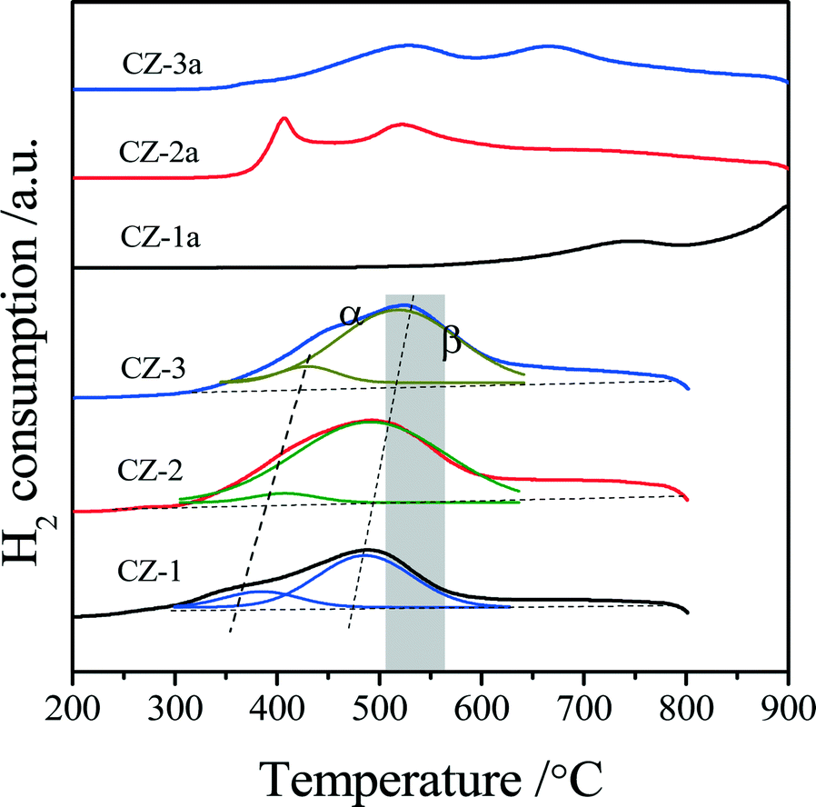 | ||
| Fig. 8 TPR profiles of fresh and aged Ce0.5Zr0.5O2 solid solutions prepared by different methods. | ||
| Sample | OSCa (μmol[O] g−1) | OSCC (μmol[O] g−1) | |
|---|---|---|---|
| Pulse experimentb | H2-TPRc | ||
| a The amount of CO uptake upon the first CO pulse after being fully oxidized with O2 at 400 °C. b The amount of CO uptake upon all CO pulses after being fully oxidized with O2 at 400 °C. c The amount of H2 consumption in the TPR process, which were calibrated with CuO reduction as a standard. | |||
| CZ-1 | 113 | 874 | 820 |
| CZ-2 | 128 | 1205 | 1145 |
| CZ-3 | 89 | 954 | 1034 |
| CZ-1a | 48 | 320 | 300 |
| CZ-2a | 62 | 615 | 527 |
| CZ-3a | 50 | 350 | 450 |
For the aged samples, there are different TPR profiles with two reduction peaks. In the TPR profile of CZ-1a, two peaks appeared at 750 °C and 900 °C and should be ascribed to the reduction of bulk oxygen of ceria. Thus it follows that the separation of the Ce-rich and Zr-rich phases occurred after calcination at 1100 °C. In the TPR curves of CZ-2a and CZ-3a, there are two reduction peaks, but their top temperatures are completely different. The two top temperatures of CZ-2a are almost the same as those of CZ-2, but the reduction peaks of CZ-3a have shifted to a higher temperature of about 120–140 °C. These results show that the CZ-2 sample prepared by the complexing–coprecipitation (CC) method has a high thermal stability, which should be attributed to its smaller crystallites (Table 1) among the three aged samples at 1100 °C because of the easier reduction of smaller crystallites for the Ce0.5Zr0.5O2 solid solution.36,47
 | ||
| Fig. 9 CO pulse testing over (A) CZ-1, (B) CZ-2, and (C) CZ-3 and (D) the CO consumption in each pulse as a function of number of CO pulses at 400 °C. | ||
3.5. CO oxidation
CO oxidation was used as a model reaction to evaluate the effect of preparation method on the catalytic property and thermal stability of the Ce0.5Zr0.5O2 solid solution. As shown in Fig. 10A, the catalytic activities of fresh CZ samples are decreased in the order CZ-2 (T50 = 285 °C) > CZ-1 (310 °C) > CZ-3 (328 °C) (T50 is the reaction temperature at 50% CO conversion), which is the same as their rank for OSC and OSCC. For the aged samples, a variation of their catalytic activities is also the same as their OSC and OSCC: CZ-2a > CZ-3a > CZ-1a. These results show that the catalytic activity of Ce0.5Zr0.5O2 solid solution for CO oxidation is tightly ascribed to its surface oxygen reducibility and bulk oxygen mobility, and the CZ-2 prepared by the complexing–coprecipitation (CC) method exhibits the best reducibility and oxygen mobility. | ||
| Fig. 10 Conversion of CO over (A) fresh and aged CZ, (B) fresh and (C) aged 1 wt% Pd/CZ (1000 ppm CO + 20% O2/Ar, GHSV of 30000 h−1). | ||
The catalytic activities of the fresh and aged 1 wt% Pd/CZ catalysts for CO oxidation are shown in Fig. 10B and C. The results show that the T50 of these fresh samples was ranked in the following order: Pd/CZ-2 (T50 = 68 °C) < Pd/CZ-3 (77 °C) < Pd/CZ-1 (82 °C). After the 1% Pd/CZ was calcined at 1100 °C for 6 h, the T50 of Pd/CZ-2a was raised to 120 °C and the activity of Pd/CZ-1a obviously declined, with its T50 reaching 170 °C. These results show that as a Pd catalyst support the CZ-2 solid solution is better than the other two samples, which should be attributable to its high thermostability, including large surface area, high OSC or reducibility, and small particle sizes. The effect of the nature of CZSS on the physicochemical properties and the interaction between Pd species and CeO2–ZrO2 support will be deeply and systematically investigated.
As shown in Fig. 11, when the feed gas contained 5% H2O, the catalytic activities of fresh CZ samples somewhat decreased, and their T50 was changed in the order CZ-1 (330 °C) ≈ CZ-2 (340 °C) > CZ-3 (400 °C). After the CZ samples were aged at 1100 °C for 6 h, their catalytic activities were decreased remarkably; for instance, the T50 of CZ-2a and CZ-3a reached 515 °C, and the catalytic activity of CZ-1a was very low: only 20% CO conversion at 650 °C. For the Pd/CZ samples, it is interesting that the T50 of Pd/CZ-2 and Pd/CZ-1 was only 50 °C in the presence of 5% H2O and obviously lower than their T50 (68 °C over Pd/CZ-2, and 82 °C over Pd/CZ-1) without water, and the T50 of Pd/CZ-3 was 70 °C in the presence of 5% H2O and lower than that (77 °C) without water, which shows that the presence of H2O could increase the catalytic activity of Pd/CZ catalysts for CO oxidation. After being aged at 1100 °C for 6 h, the T50 of Pd/CZ-2a (or Pd/CZ-3a) increased from 50 °C (or 70 °C) to 70 °C (or 110 °C), and the catalytic activity of Pd/CZ-1a was insanely decreased and its T50 reached 255 °C. This is because in the process of CO reacting with lattice O, the H2O molecule also reacts with CO, forming the absorbed intermediate, COOH(ad), which can be decomposed to CO2 and H. Then, the H from H2O and COOH reacts with the absorbed O to form H2O and CO2.60
 | ||
| Fig. 11 Conversion of CO over (A) fresh and aged CZ, (B) fresh and aged 1 wt% Pd/CZ (1000 ppm CO + 20% O2 + 5% H2O/Ar, GHSV of 30000 h−1). | ||
Now, we conclude that when these catalysts were used in the feed gas with 5% H2O, the performance of CZ-2 is almost be same as that of CZ-1 as the catalyst or Pd catalyst support for the CO oxidation. For the CZ samples aged at 1100 °C for 6 h, CZ-2a prepared by the complexing–coprecipitation method exhibits much higher thermostability than CZ-1a prepared by the coprecipitation method, especially when CZ was used as the support for the Pd catalyst. Therefore, we can supply high-performance and thermally stable ceria–zirconia solid solutions for three-way catalysts for automobile emission control.
4. Conclusions
In summary, a new complexing–coprecipitation (CC) method for the preparation of the Ce–Zr solid solution was designed, and with the help of this method more homogeneous nanodisperse and porous Ce0.5Zr0.5O2 (CZ-2) particles were successfully prepared. Based on the characterizations of the structural, textural and physicochemical properties of the samples, it was found that Ce0.5Zr0.5O2 prepared by the CC method existed as the t′′-phase with rich oxygen defects and surface Ce3+ and has a bigger specific surface area, uniform particle and pore size, excellent bulk oxygen migration and redox abilities than the samples prepared by the coprecipitation method or the complexing–coprecipitation-solution method. After this CZ-2 sample was calcined at 1100 °C for 6 h, its surface area, OSC (and OSCC, oxygen storage capacity complete) and catalytic activity for the oxidation of CO were still the best among the three Ce–Zr solid solutions prepared by the three methods whether it was used as the catalyst or as support for the Pd catalyst, reflecting its good thermostability, although its particle and pore sizes were somewhat increased. These results show that the physicochemical properties and catalytic activity for the CO oxidation as well as the redox behaviors (or OSC and OSCC) of the Ce0.5Zr0.5O2 solid solutions strongly depend on the preparation methods. The complexing–coprecipitation (CC) method is a very effective and simple route to prepare ceria–zirconia solid solutions with high oxygen storage capacity and thermal stability.Acknowledgements
This project was financially supported by the National Natural Science Foundation of China (21273150, 21171055), the National Basic Research Program of China (2013CB933201), the National High Technology Research and Development Program of China (2011AA03A406, 2012AA111717), and Fundamental Research Funds for the Central Universities (WK1214007).References
- B. Zhao, G. Li, C. Ge, Q. Wang and R. Zhou, Appl. Catal., B, 2010, 96, 338–349 CrossRef CAS.
- Q. Liang, X. Wu, D. Weng and Z. Lu, Catal. Commun., 2008, 9, 202–206 CrossRef CAS.
- L. Liu, Z. Yao, B. Liu and L. Dong, J. Catal., 2010, 275, 45–60 CrossRef CAS.
- L. Liu, Y. Chen, L. Dong, J. Zhu, H. Wan, B. Liu, B. Zhao, H. Zhu, K. Sun, L. Dong and Y. Chen, Appl. Catal., B, 2009, 90, 105–114 CrossRef CAS.
- M. Kantcheva, O. Samarkaya, L. Ilieva, G. Pantaleo, A. M. Venezia and D. Andreeva, Appl. Catal., B, 2009, 88, 113–126 CrossRef CAS.
- P. Esteves, Y. Wu, C. Dujardin and P. Granger, Catal. Today, 2011, 176, 453–457 CrossRef CAS.
- W. Cai, Q. Zhong and Y. Zhao, Catal. Commun., 2013, 39, 30–34 CrossRef CAS.
- L. Zhang, D. Weng, B. Wang and X. Wu, Catal. Commun., 2010, 11, 1229–1232 CrossRef CAS.
- D. Sellick, A. Aranda, T. García, J. López, B. Solsona, A. Mastral, D. Morgan, A. Carley and S. Taylor, Appl. Catal., B, 2013, 132–133, 98–106 CrossRef CAS.
- Z. Wang, Z. Qu, X. Quan and H. Wang, Appl. Catal., A, 2012, 411–412, 131–138 CrossRef CAS.
- C. Kalamaras, D. Dionysiou and A. Efstathiou, ACS Catal., 2012, 2, 2729–2742 CrossRef CAS.
- W. Han, P. Zhang, Z. Tang, X. Pan and G. Lu, J. Sol-Gel Sci. Technol., 2013, 66, 526–532 CrossRef CAS.
- C. Hori, H. Permana, K. Simon Ng, A. Brenner, K. More, K. Rahmoeller and D. Belton, Appl. Catal., B, 1998, 16, 105–117 CrossRef CAS.
- J. González-Velasco, M. Gutiérrez-Ortiz, J. Marc, J. Botas, M. González-Marcos and G. Blanchard, Ind. Eng. Chem. Res., 2003, 42, 311–317 CrossRef.
- J. Fan, X. Wu, R. Ran and D. Weng, Appl. Surf. Sci., 2005, 245, 162–171 CrossRef CAS.
- J. Anderson, R. Daley, S. Christou and A. Efstathiou, Appl. Catal., B, 2006, 64, 189–200 CrossRef CAS.
- Y. Guo, G. Lu, Z. Zhang, S. Zhang, Y. Qi and Y. Liu, Catal. Today, 2007, 126, 296–302 CrossRef CAS.
- Y. Nagai, T. Yamamoto, T. Nonaka, S. Yoshida, T. Nonaka, T. Okamoto, A. Suda and M. Sugiura, Catal. Today, 2002, 74, 225–234 CrossRef CAS.
- A. Laachir, V. Perrichon, A. Badri, J. Lamotte, E. Catherine, J. C. Lavalley, J. El Fallah, L. Hilarie, F. Le Normand, E. Quemere, G. N. Sauvion and O. Touret, J. Chem. Soc., Faraday Trans., 1991, 87, 1601–1609 RSC.
- H. Y. Li, H. F. Wang, X. Q. Gong, Y. L. Guo, Y. Guo, G. Z. Lu and P. Hu, Phys. Rev. B: Condens. Matter Mater. Phys., 2009, 79, 193401–193404 CrossRef.
- S. Damyanova, B. Pawelec, K. Arishtirova, M. V. Martinez Huerta and J. L. G. Fierro, Appl. Catal., A, 2008, 337, 86–96 CrossRef CAS.
- W. C. Zhan, Y. Guo, X. Q. Gong, Y. L. Guo, Y. Q. Wang and G. Z. Lu, Chin. J. Catal., 2014, 35, 1238–1250 CrossRef CAS.
- H. F. Wang, X. Q. Gong, Y. L. Guo, Y. Guo, G. Z. Lu and P. Hu, J. Phys. Chem. C, 2009, 113, 10229–10232 CAS.
- W. C. Zhan, Y. Guo, Y. L. Guo, X. Q. Gong, Y. Q. Wang and G. Z. Lu, Zhongguo Kexue: Huaxue, 2012, 42, 1289–1307 CAS.
- S. Letichevsky, C. Tellez, R. De avillez, M. Da Silva, M. Fraga and L. Appel, Appl. Catal., B, 2005, 58, 203–210 CrossRef CAS.
- E. Aneggi, C. De Leitenburg and A. Trovarelli, Catal. Today, 2012, 181, 108–115 CrossRef CAS.
- Y. Liu, C. Wen, Y. Guo, G. Lu and Y. Wang, J. Phys. Chem. C, 2010, 114, 9889–9897 CAS.
- M. Thammachart, V. Meeyoo, T. Risksomboon and S. Osuwan, Catal. Today, 2001, 68, 53–61 CrossRef CAS.
- A. Kozlov, D. Kim, A. Yezerets, P. Andersen, H. Kung and M. Kung, J. Catal., 2002, 209, 417–426 CrossRef CAS.
- M. Alifanti, B. Baps, N. Blangenois, J. Naud, P. Grange and B. Delmon, Chem. Mater., 2003, 15, 395–403 CrossRef CAS.
- M. Epifani, T. Andreu, S. Abdollahzadeh-Ghom, J. Arbiol and J. R. Morante, Adv. Funct. Mater., 2012, 22, 2867–2875 CrossRef CAS.
- J. Kim, W. Myeong and S. Ihm, J. Catal., 2009, 263, 123–133 CrossRef CAS.
- N. Laosiripojana and S. Assabumrungrat, Appl. Catal., B, 2005, 60, 107–116 CrossRef CAS.
- X. Liang, X. Wang, Y. Zhuang, B. Xu, S. Kuang and Y. Li, J. Am. Chem. Soc., 2008, 130, 2736–2737 CrossRef CAS PubMed.
- J. Wang, M. Shen, Y. An and J. Wang, Catal. Commun., 2008, 10, 103–107 CrossRef CAS.
- Q. Y. Wang, G. F. Li, B. Zhao, M. Q. Shen and R. X. Zhou, Appl. Catal., B, 2010, 101, 150–159 CrossRef CAS.
- G. Li, Q. Wang, B. Zhao and R. Zhou, Appl. Catal., B, 2011, 105, 151–162 CrossRef CAS.
- Q. Wang, G. Li, B. Zhao and R. Zhou, J. Hazard. Mater., 2011, 189, 150–157 CrossRef CAS PubMed.
- P. Huang, H. Jiang and M. Zhang, J. Rare Earths, 2012, 30, 524–528 CrossRef CAS.
- Q. Wang, G. Li, B. Zhao and R. Zhou, J. Mol. Catal. A: Chem., 2011, 339, 52–60 CrossRef CAS.
- V. Raju, S. Jaenicke and G. Chuah, Appl. Catal., B, 2009, 91, 92–100 CrossRef CAS.
- R. Si, Y. Zhang, L. Wang, S. Li, B. Lin, W. Chu, Z. Wu and C. Yan, J. Phys. Chem. C, 2007, 111, 787–794 CAS.
- H. F. Wang, X. Q. Gong, Y. L. Guo, Y. Guo, G. Z. Lu and P. Hu, Angew. Chem., Int. Ed., 2009, 48, 8289–8292 CrossRef CAS PubMed.
- G. Vlaic, P. Fornasiero, S. Geremia, J. Kašpar and M. Graziani, J. Catal., 1997, 168, 386–392 CrossRef CAS.
- S. Lemaux, A. Bensaddik, A. Van der Eerden, J. Bitter and D. Koningsberger, J. Phys. Chem. B, 2001, 105, 4810–4815 CrossRef CAS.
- M. Yashima, T. Sekikawa, D. Sato, H. Nakano and K. Omoto, Cryst. Growth Des., 2013, 13, 829–837 CAS.
- G. Li, B. Zhao, Q. Wang and R. Zhou, Appl. Catal., B, 2010, 97, 41–48 CrossRef CAS.
- X. Weng, B. Perston, X. Wang, I. Arahams, T. Lin, S. Yang, J. Evans, D. Morgan, A. Carley, M. Bowker, J. Knowles, I. Rehman and J. Darr, Appl. Catal., B, 2009, 90, 405–415 CrossRef CAS.
- M. Daturi, E. Finocchio, C. Binet, J.-C. Lavalley, F. Fally, V. Perrichon, H. Vidal, N. Hickey and J. Kašpar, J. Phys. Chem. B, 2000, 104, 9186–9194 CrossRef CAS.
- R. Di Monte and J. Kašpar, J. Mater. Chem., 2005, 15, 633–648 RSC.
- P. Fornasiero, G. Balducci, R. Di Monte, J. Kašpar, V. Sergo, G. Gubitosa, A. Ferrero and M. Graziani, J. Catal., 1996, 164, 173–183 CrossRef CAS.
- T. Murota, T. Hasegawa, S. Aozasa, H. Matsui and M. Motoyama, J. Alloys Compd., 1993, 193, 298–299 CrossRef CAS.
- L. H. Reddy, G. K. Reddy, D. Devaiah and B. M. Reddy, Appl. Catal., A, 2012, 445–446, 297–305 CrossRef CAS.
- E. Mamontov, T. Eganmi, R. Brezny, M. Koranne and S. Tyagi, J. Phys. Chem. B, 2000, 104, 11110–11116 CrossRef CAS.
- L. Liotta, A. Longo, A. Macaluso, A. Martorana, G. Pantaleo, A. Venzia and G. Deganello, Appl. Catal., B, 2004, 48, 133–149 CrossRef CAS.
- J. Fan, X. Wu, X. Wu, Q. Liang, R. Ran and D. Weng, Appl. Catal., B, 2008, 81, 38–48 CrossRef CAS.
- M. Alexandrou and R. M. Nix, Surf. Sci., 1994, 321, 47–57 CrossRef CAS.
- Q. Wang, D. Li, B. Zhao and R. Zhou, Appl. Catal., B, 2010, 100, 516–528 CrossRef CAS.
- X. H. Wang, G. Z. Lu, Y. Guo, L. Z. Jiang, Y. L. Guo and C. Z. Li, J. Mater. Sci., 2009, 44, 1294–1301 CrossRef CAS.
- G. N. Li, L. Li, Y. Yuan, J. J. Shi, Y. Y. Yuan, Y. S. Li, W. R. Zhao and J. L. Shi, Appl. Catal., B, 2014, 158–159, 341–347 CrossRef CAS.
| This journal is © The Royal Society of Chemistry 2016 |