Photocatalytic and photoelectrocatalytic reduction of CO2 using heterogeneous catalysts with controlled nanostructures
Shunji
Xie
,
Qinghong
Zhang
*,
Guodong
Liu
and
Ye
Wang
*
State Key Laboratory of Physical Chemistry of Solid Surfaces, Collaborative Innovation Center of Chemistry for Energy Materials, National Engineering Laboratory for Green Chemical Production of Alcohols, Ethers and Esters, College of Chemistry and Chemical Engineering, Xiamen University, Xiamen 361005, China. E-mail: wangye@xmu.edu.cn; zhangqh@xmu.edu.cn; Fax: +86-592-2183047; Tel: +86-592-2186156
First published on 30th October 2015
Abstract
The development of efficient artificial photocatalysts and photoelectrocatalysts for the reduction of CO2 with H2O to fuels and chemicals has attracted much attention in recent years. Although the state-of-the-art for the production of fuels or chemicals from CO2 using solar energy is still far from practical consideration, rich knowledge has been accumulated to understand the key factors that determine the catalytic performances. This Feature article highlights recent advances in the photocatalytic and photoelectrocatalytic reduction of CO2 with H2O using heterogeneous semiconductor-based catalysts. The effects of structural aspects of semiconductors, such as crystalline phases, particle sizes, morphologies, exposed facets and heterojunctions, on their catalytic behaviours are discussed. The roles of different types of cocatalysts and the impact of their nanostructures on surface CO2 chemisorption and reduction are also analysed. The present article aims to provide insights into the rational design of efficient heterogeneous catalysts with controlled nanostructures for the photocatalytic and photoelectrocatalytic reduction of CO2 with H2O.
1. Introduction
The diminishing of fossil resources and the growing emission of CO2 have stimulated research activities towards the utilization of CO2 as a carbon source for the production of fuels and chemicals.1 However, CO2 is one of the most stable molecules. Thermodynamically, the conversion of CO2 is typically an endothermic process, which requires a significant energy input and/or a high-energy reactant. The dissociation energy of the C![[double bond, length as m-dash]](https://www.rsc.org/images/entities/char_e001.gif) O bond in CO2 is ∼750 kJ mol−1, higher than those of many other chemical bonds such as C–H (∼430 kJ mol−1) and C–C (∼336 kJ mol−1) bonds. Generally, a high activation barrier should be overcome for the transformation of CO2. The thermodynamic stability and kinetic inertness of CO2 make the transformation of CO2 a highly challenging research theme in chemical science. The transformation of CO2 can typically proceed via the following routes: (1) the co-feeding of a high-energy reactant such as H2, unsaturated compounds, small-membered ring compounds (e.g., epoxides) and organometallic compounds; and (2) the supply of external energy such as solar energy or electrical energy.
O bond in CO2 is ∼750 kJ mol−1, higher than those of many other chemical bonds such as C–H (∼430 kJ mol−1) and C–C (∼336 kJ mol−1) bonds. Generally, a high activation barrier should be overcome for the transformation of CO2. The thermodynamic stability and kinetic inertness of CO2 make the transformation of CO2 a highly challenging research theme in chemical science. The transformation of CO2 can typically proceed via the following routes: (1) the co-feeding of a high-energy reactant such as H2, unsaturated compounds, small-membered ring compounds (e.g., epoxides) and organometallic compounds; and (2) the supply of external energy such as solar energy or electrical energy.
The hydrogenation of CO2 to methanol and formic acid has been intensively studied using heterogeneous and homogeneous catalysts.2 CO2 can be used for the production of dimethyl carbonate and cyclic carbonate through the reaction with methanol or epoxides.3 However, these reactions are thermodynamically limited and the equilibrium conversions are low under mild conditions. The use of CO2 for the reformation of CH4 to produce syngas (H2/CO) could also proceed, but high temperatures and large energy-inputs are required.4
In nature, the photosynthesis of green plants transforms CO2 with H2O under sunlight to carbohydrates and O2 at room temperature. Inspired by this natural process, a lot of research activities have been devoted to developing artificial or synthetic photocatalysts for the reduction of CO2 with H2O to organic compounds as well as CO. Some homogeneous or molecular photocatalysts, in particular metal complexes such as Re and Ru complexes, have been reported for the activation and reduction of CO2, providing CO and formate as the major products.5 Fujishima, Honda and their co-workers reported a pioneering work for the photocatalytic reduction of CO2 in water in the presence of heterogeneous semiconductor powders suspended in water.6 Since then, a large number of semiconductors such as TiO2, BaLa4Ti4O15, SrTiO3, WO3 nanosheets, NaNbO4, KNbO4, Sr2Nb2O7, Zn2GeO4, Zn2GaO4, Zn2SnO4 and some metal sulphides have been reported to be capable of catalyzing the photoreduction of CO2 with H2O, and the pace has increased enormously in the recent five years.7–21
The electrochemical reduction of CO2 is another important route for the transformation of CO2 to chemicals and fuels. Recently, encouraging results have been achieved for the electrochemical reduction of CO2 to hydrocarbons (e.g., CH4 and C2H4) and alcohols (e.g., CH3OH and CH3CH2OH), which can be used as fuels or chemicals, in addition to CO and formate.22–26 However, the catalytic activity, product selectivity and catalyst stability are still much far from the requirements for commercial consideration. Furthermore, a large amount of electricity must be supplied because of the high overpotentials for CO2 reduction.
An alternative approach for CO2 transformation is the photoelectrocatalysis, which integrates photocatalysis and electrocatalysis. There are some distinct advantages of photoelectrocatalytic reduction of CO2 with H2O. First, the use of solar energy can significantly lower the applied voltage, thus decreasing the electricity consumption. Second, the imposition of an external bias voltage can drive the separation of photogenerated electrons and holes, which is one of the most important steps determining the photocatalytic efficiency. Furthermore, the employment of separated half cells can avoid the re-oxidation of the reactive products such as methanol, which is known to be oxidized by photogenerated holes more easily than H2O in a conventional photocatalytic system. The photoelectrocatalytic reduction of CO2 was first reported by Halmann,27 who used a p-type GaP as a photocathode and observed the formation of HCOOH, HCHO and CH3OH in the electrolyte solution after the irradiation of GaP in combination with an applied bias voltage. This research direction has been attracting more and more attention in recent years.28,29
In short, the photocatalysis and photoelectrocatalysis are two highly attractive routes for the reduction of CO2 with H2O to fuels and chemicals using solar energy. Although many research articles and review papers have already appeared,7–21,28,29 the progress in these areas is largely behind that in the photocatalytic and photoelectrocatalytic splitting of H2O. In most cases, the strategies typically adopted for H2O splitting have also been exploited for CO2 reduction. However, the activation of CO2 is more difficult than that of H2O. The reduction of CO2 by photogenerated electrons may be a competitive process with the reduction of H2O, thus making the catalyst requirement for the two processes quite different. Moreover, the products in the reduction of CO2 are much more complicated than in the reduction of H2O, which produces only H2. A variety of products (e.g., CO, HCOOH, HCHO, CH3OH, CH4, higher hydrocarbons and higher alcohols) may be formed in the reduction of CO2 with H2O. Fundamental insights for the photoreduction of CO2 in the presence of H2O have not been well documented in the review papers reported to date. For example, many articles reported the synthesis of nanostructured semiconductors for the photocatalytic reduction of CO2, but the knowledge on how the structure (such as the crystalline phase, particle size, morphology and preferentially exposed facet) determines the photocatalytic activity and selectivity is still lacking. Co-catalysts are known to play crucial roles in a photocatalytic process.30 However, the roles of co-catalysts in enhancing the reduction of CO2 or H2O and the formation of different products are still ambiguous. The effect of nanostructures of dual co-catalysts on their functions in the photocatalytic reduction of CO2 needs deeper elucidation. Furthermore, so far much attention has been paid to the energy-band engineering of semiconductors, which is helpful for enhancing the light harvesting and the electron–hole separation. The knowledge on how to manipulate the surface and interface structures to tune the CO2/H2O chemisorption and activation is relatively poorly accumulated.
This Feature article will highlight recent advances in the fundamental understanding of the effects of structures of both semiconductors and co-catalysts on the photocatalytic and photoelectrocatalytic reduction of CO2 with H2O and the formation of different products. Besides the efficiency of photogenerated electrons used for reduction reactions, we will pay particular attention to discuss the factors determining the selectivity of the reacted electrons for CO2 reduction and the selectivity of reduction products.
2. Photocatalysis
2.1 Fundamental aspects for photocatalytic reduction of CO2
It is generally accepted that the semiconductor-based photocatalysis for the reduction of CO2 with H2O involves three main steps (Fig. 1). In the first step, electron–hole pairs are generated when a semiconductor photocatalyst is illuminated by an appropriate light source with its energy equal or greater than the band-gap energy (Eg) of the semiconductor. Then, the generated electrons and holes migrate to the surface of the semiconductor or a co-catalyst in contact with the semiconductor in the second step (Fig. 1iia). It should be mentioned that only a fraction of carriers can reach the surface of the semiconductor or co-catalyst. A large fraction of electron–hole pairs recombine together (Fig. 1iib), with the energy being released in the form of heat or photons. In the third step, the photogenerated electrons reduce CO2, which is adsorbed on catalyst surfaces, into CO, HCOOH, CH3OH or CH4, whereas the holes oxidize H2O to O2. The first and second steps are the same as those in the splitting of H2O. The third step is peculiar to the reduction of CO2. The reduction of H2O could also proceed in competition with that of CO2.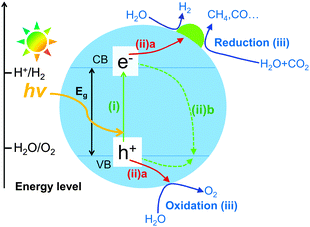 | ||
| Fig. 1 Schematic illustration of the basic mechanism of photocatalytic reduction of CO2 with H2O on a semiconductor photocatalyst. | ||
Similar to that for most photocatalytic reactions including H2O splitting, the photocatalytic efficiency for CO2 reduction is mainly determined by the efficiencies of the light harvesting, the charge separation and the surface reaction. In particular, because the charge recombination (∼10−9 s) is usually a much faster process as compared to the reaction process (∼10−3–10−8 s), the acceleration of electron–hole separation is of paramount importance for almost all the photocatalytic reactions. This is also a key issue in the photocatalytic reduction of CO2. The present article will also highlight some useful strategies that can enhance CO2 reduction by facilitating the electron–hole separation. In particular, the construction of semiconductors with specific nanostructures, the creation of heterojunctions and the use of suitable co-catalysts will be emphasized.
Some possible reactions related to the reduction of CO2 and the corresponding redox potentials are summarized in Table 1. HCOOH, CO, HCHO, CH3OH and CH4 are all possible products from CO2. Fig. 2 displays the band-edge positions of some typical semiconductors. Thermodynamically, the semiconductor, which is capable of catalyzing the reduction of CO2 with H2O, should possess the conduction-band edge higher or more negative than the redox potential for CO2 reduction. At the same time, the valence-band edge should be lower or more positive than the redox potential for the oxidation of H2O to O2. The photogenerated electrons can thus be used for the reduction of CO2 and the holes for the oxidation of H2O to O2. The formation of CH4 and CH3OH, which are eight- and six-electron reduction, are thermodynamically more feasible because of their less negative redox potentials. It should be noted that CH3OH is known to be a much better hole scavenger than H2O. Thus, CH3OH cannot be obtained with considerable amounts if the reduction and oxidation take place on the same catalyst or in the same reactor. In our opinion, the photocatalytic reduction of CO2 to CH4 should be a more promising target if one-compartment reactor is employed.
| Reaction | E 0 (V) vs. NHE (pH = 7) |
|---|---|
| CO2 + 2H+ + 2e− → HCOOH | −0.61 |
| CO2 + 2H+ + 2e− → CO + H2O | −0.53 |
| CO2 + 4H+ + 4e− → HCHO + H2O | −0.48 |
| CO2 + 6H+ + 6e− → CH3OH + H2O | −0.38 |
| CO2 + 8H+ + 8e− → CH4 + 2H2O | −0.24 |
| 2H+ + 2e− → H2 | −0.41 |
| H2O + 2h+ → 1/2O2 + 2H+ | 0.82 |
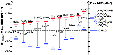 | ||
| Fig. 2 Band-edge positions of some typical semiconductor photocatalysts relative to the energy levels of the redox couples involved in the reduction of CO2. | ||
Because the redox potentials for CO2 reduction are close to that for the reduction of H2O to H2 (Fig. 2), the photocatalyst, which works for the reduction of CO2, may also catalyse the reduction of H2O (or H+) to H2. In addition, the activation of H2O is generally much easier than that of CO2. Moreover, if CH4 is the main target, the formation of CH4 needs eight electrons, which would be more difficult than the formation of H2 from H2O, a two-electron reduction. Thus, the reduction of H2O to H2 is kinetically more favourable and is a strong competitive reaction with the reduction of CO2. To evaluate the efficiency of CO2 reduction, we can calculate the selectivity of the reacted electrons for CO2 reduction as follows:
| Selectivity for CO2 reduction (%) = (number of electrons reacted for CO2 reduction/number of electrons involved in all reduction reactions) × 100%. |
Therefore, the surface manipulation is crucial to enhancing the photocatalytic reduction of CO2 in the presence of H2O. To obtain a high efficiency for CO2 reduction, the catalyst surface should possess a high ability to chemisorb and activate CO2 molecules in the presence of H2O. The present article will also discuss useful strategies such as the modification of the semiconductor surface and the fabrication of suitable co-catalysts to enhance surface conversion of CO2 kinetically.
Similar to the pioneering work reported by Fujishima and Honda,6 most of the reported studies adopted a solid–liquid interface reaction mode for photocatalytic reduction of CO2.13 In such a mode (Fig. 3A), the photocatalyst particles were dispersed or suspended in the aqueous solution, where CO2 was dissolved. The solid–liquid interface reactions occurred. However, the direct contact of the catalyst with liquid H2O and the limited solubility of CO2 in H2O would cause the preferential adsorption of H2O on catalyst surfaces, limiting the reduction of CO2 by the photogenerated electrons. To increase the solubility of CO2 in the aqueous phase, an alkaline medium has been employed for photocatalytic reduction of CO2.13,31 However, the formed CO32− or HCO3− is typically more difficult to reduce than CO2, and CO32− is known as a good hole quencher.31 The use of a solid–gas or solid–vapour interface reaction mode (Fig. 3B) may overcome these limitations and may increase the rate of CO2 reduction. For example, when a TiO2 (P25) or Pt–TiO2 catalyst was placed on a catalyst holder surrounded by CO2 and H2O vapour, the rate of CH4 formation increased for more than 3 times as compared to that by dispersing the catalyst in water (Table 2).32 At the same time, the rate of H2 formation from the reduction of H2O decreased by using the solid–vapour reaction mode. The selectivity of reacted electrons for CO2 reduction increased significantly from 11–19% to 40–56% (Table 2). This indicates that the solid–vapour reaction mode is more suitable for the preferential reduction of CO2 in the presence of H2O. It is of interest that the rate of photogenerated electrons used for all the reduction reactions did not significantly change by changing the reaction mode (Table 2). The use of solid–liquid or solid–vapour reaction mode mainly determined the selectivity of the reacted electrons for H2O reduction or for CO2 reduction.
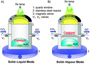 | ||
| Fig. 3 Two typical reaction modes for photocatalytic reduction of CO2 in the presence of H2O.32 Reproduced from ref. 32 with permission from American Chemical Society. (A) Solid–liquid interface reaction mode. (B) Solid–vapour interface reaction mode. | ||
![[thin space (1/6-em)]](https://www.rsc.org/images/entities/char_2009.gif) 32
32
| Reaction mode | Catalyst | Formation rate (μmol g−1 h−1) | R (electron) (μmol g−1 h−1) | Select. for CO2 red. (%) | ||
|---|---|---|---|---|---|---|
| CO | CH4 | H2 | ||||
| a Reaction conditions: catalyst, 0.020 g; CO2 pressure, 0.2 MPa; H2O, 4.0 mL; irradiation time, 10 h. Reproduced from ref. 32 with permission from American Chemical Society. | ||||||
| Solid–liquid | TiO2 | 0.80 | 0.11 | 5.3 | 13 | 19 |
| Solid–vapour | TiO2 | 1.2 | 0.38 | 2.1 | 10 | 56 |
| Solid–liquid | Pt–TiO2 | 0.76 | 1.4 | 55 | 123 | 11 |
| Solid–vapour | Pt–TiO2 | 1.1 | 5.2 | 33 | 111 | 40 |
2.2 Design and construction of semiconductors with controlled nanostructures for photocatalytic reduction of CO2 with H2O
The nanostructure of a semiconductor plays crucial roles in determining its photocatalytic performance. Many structural parameters can affect the kinetics of the photocatalytic processes including photo-absorption, electron–hole separation and surface reaction. Here, we will analyse the effects of structural aspects of semiconductors, including the crystalline phases, sizes of nanoparticles, morphologies, exposed facets and heterojunctions on the photocatalytic reduction of CO2 with H2O. Some results of the related photocatalytic systems are summarized in Table 3.| Photocatalyst | Formation rate (μmol g−1 h−1) | Light source | Ref. |
|---|---|---|---|
| Effect of crystalline phase | |||
| Brookite TiO2 (He treated at 493 K) | CO: 2.8, CH4: 0.32 | Xe lamp | 37 |
| Pt-cubic NaNbO3 | CH4: 4.9 | Xe lamp | 38 |
| Pt-orthorhombic NaNbO3 | CH4: 2.5 | 39 | |
| TiO2 (anatase + rutile) | CH4: 34 | Hg lamp | 40 |
| P25 | CH4: 14 | ||
| TiO2 (73% anatase + 27% brookite) | CH3OH: 0.59 | Xe lamp (UV-vis) | 43 |
| P25 | CH3OH: 0.18 | ||
| TiO2 (75% anatase + 25% brookite) | CO: 2.1 | Solar simulator (Oriel) | 44 |
| P25 | CO: 1.3 | ||
| Effect of particle size | |||
| Anatase TiO2 (optimized size: 14 nm) | CH4: 0.17 μmol m−2 | Hg lamp (254 nm) | 47 |
| Effect of morphology | |||
| Pt–Cu/N-doped TiO2 nanotube arrays | Hydrocarbons: 111 ppm cm−2 h−1, H2: 160 ppm cm−2 h−1 | AM 1.5 | 48 |
| 1% RuO2 and 1% Pt co-loaded Zn2GeO4 nanoribbons | CH4: 6.7 | Xe lamp | 49 |
| Hexagonal Zn2GeO4 nanorods | CO: 17.9 ppm h−1, CH4: 3.5 ppm h−1 | Xe lamp (UV-vis) | 50 |
| 1% RuO2 and 1% Pt co-loaded Zn1.7GeN1.8O nanosheaves | CH4: 4.4 | Xe lamp (>420 nm) | 51 |
| 1% RuO2 loaded Cd2Ge2O6 nanowires | CH4: 0.72 | Xe arc lamp (UV-vis) | 52 |
| 1% Pt loaded In2Ge2O7 nanowires | CO: 0.51 | Xe lamp | 53 |
| 1% RuO2 + 1% Pt co-loaded Na2V6O16 nanoribbons | CH4: 0.18 | Xe lamp (>420 nm) | 54 |
| Fe2V4O13 nanoribbons | CH4: 0.7 (UV-vis), CH4: 0.2 (Vis) | Xe lamp | 55 |
| Ultrathin W18O49 nanowires | CH4: 667 ppm g−1 h−1 | Xe lamp (>420 nm) | 56 |
| G-Ti0.91O2 hollow spheres | CH4: 1.2, CO: 9.0 | Xe lamp | 57 |
| P25 | CH4: 0.8, CO: 0.2 | ||
| 0.5% G/TiO2 nanosheets | CH4: 9.3 μmol m−2 h−1 | 365 nm | 58 |
| ZnGa2O4 nanosheet microspheres | CH4: 6.9 ppm h−1 | Xe lamp | 59 |
| 1% RuO2–1% Pt co-loaded Zn2SnO4 nanosheet micro-octahedrons | CH4: 36 ppm g−1 h−1 | Xe lamp | 60 |
| HNb3O8 nanobelts | CH4: 3.85 | Xe lamp | 61 |
| P25 | CH4: 0.37 | ||
| KTaO3 nanoflakes | CO: 62 ppm g−1 h−1, H2: 1323 ppm g−1 h−1 | Xe lamp | 62 |
| SrNb2O6 nanoplates | CH4: 3.3, CO: 16.6, H2: 6.5 | Xe lamp (320–780 nm) | 63 |
| P25 | CH4: 0.42, CO: 1.4, H2: 2.4 | ||
| WO3 nanosheets (thickness: ∼4–5 nm) | CH4: 1.1 | Xe lamp (>420 nm) | 64 |
| Rectangular sheet-like WO3 with dominant {002} | CH4: 0.34 | Xe lamp | 65 |
| Bi2WO6 nanoplates with dominant {001} | CH4: 1.1 | Xe lamp (>420 nm) | 66 |
| Effect of exposed facet | |||
| 1% Pt/TiO2 rods with dominant {010} | CH4: 2.5 | Xe lamp | 72 |
| 1% Pt/P25 | CH4: 2.0 | ||
| Hollow anatase TiO2 mesocrystals with dominant {101} facets | CH4: 1.2 | Xe lamp | 73 |
| Anatase TiO2 nanosheets exposed with 95% {100} facets | CH4: 5.8 ppm g−1 h−1 | UV-vis light (>300 nm) | 74 |
| Anatase TiO2-{010} | CH4: 1.2 | Hg lamp | 75 |
| Anatase TiO2-{101} | CH4: 0.74 | ||
| Anatase TiO2-{001} | CH4: 0.19 | ||
Fluorinated anatase TiO2 nanosheets {001}![[thin space (1/6-em)]](https://www.rsc.org/images/entities/char_2009.gif) : :![[thin space (1/6-em)]](https://www.rsc.org/images/entities/char_2009.gif) {101} = 72 {101} = 72![[thin space (1/6-em)]](https://www.rsc.org/images/entities/char_2009.gif) : :![[thin space (1/6-em)]](https://www.rsc.org/images/entities/char_2009.gif) 28 28 |
CH4: 0.20, CH3OH: 0.18, H2: 0.10 | Hg lamp | 76 |
Anatase TiO2 with {001}![[thin space (1/6-em)]](https://www.rsc.org/images/entities/char_2009.gif) : :![[thin space (1/6-em)]](https://www.rsc.org/images/entities/char_2009.gif) {101} = 58 {101} = 58![[thin space (1/6-em)]](https://www.rsc.org/images/entities/char_2009.gif) : :![[thin space (1/6-em)]](https://www.rsc.org/images/entities/char_2009.gif) 42 42 |
CH4: 1.35 | Xe lamp | 77 |
| P25 | CH4: 0.38 | ||
| Hexahedron-prism anchored octahedron CeO2{100} + {111} | CH4: 1.12 | Xe lamp | 78 |
| Effect of heterojunction | |||
| PbS–Cu/TiO2 | CO + CH4 + C2H6: 1.71 | Xe lamp (>420 nm) | 79 |
| Pt-g-C3N4/NaNbO3 | CH4: 6.4 | Xe lamp (>420 nm) | 80 |
| ZnO–TiO2 | CH4: 55 | Xe lamp | 81 |
| CuO–TiO2−xNx | CH4: 41 ppm g−1 h−1 | AM 1.5 | 82 |
| Ag3PO4/g-C3N4 | CO: 44, CH3OH: 9 | Xe lamp | 83 |
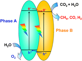
Li and co-workers recently compared photocatalytic performances of TiO2 nanocrystals with three different phases, i.e., anatase, rutile and brookite, which were synthesized by hydrolysis followed by the hydrothermal method, for the reduction of CO2 with H2O vapour.37 CO was produced as a major product together with a minor amount of CH4 over all these TiO2 catalysts. The CO formation rate was in the order of anatase > brookite > rutile if the catalysts were only calcined in air (Fig. 4). The difference in catalytic activities for the samples with different crystalline phases may arise from a complicated interplay of light harvesting, electron–hole separation and surface reaction. Interestingly, after these catalysts were further pretreated in He flow at 493 K for 1.5 h, their activities for (CO + CH4) formation were all enhanced. The enhancement was particularly significant for brookite and anatase, and the activity sequence changed to brookite > anatase > rutile after heat pretreatment in He (Fig. 4). This enhancement could be attributed to the creation of surface defective sites including Ti3+ and oxygen vacancies. These surface defective sites were proposed to be responsible for the activation of CO2. The defective site could be generated more easily on brookite and anatase, and thus these two catalysts exhibited much higher reaction rates after He pretreatment. The pretreated brookite and anatase possessed similar densities of defective sites, but their activities were different. Further in situ FT-IR studies clarified that CO2− was formed as an intermediate on both brookite and anatase surfaces, and the further reduction of CO2− in the presence of H+ resulted in CO. CO2− might react with H+ more facilely on brookite surfaces, forming HCOOH as another reaction intermediate and providing another reaction channel. Thus, the difference in the surface reactivity of TiO2 nanocrystals with different crystalline phases mainly determined the observed difference in activity for CO2 reduction.
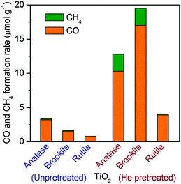 | ||
| Fig. 4 Production of CH4 and CO on TiO2 samples with different crystalline phases with and without heat treatment under He flow. | ||
Another example of the crystalline-phase effect was reported by Ye and co-workers. They synthesized NaNbO3 with cubic and orthorhombic phases.38,39 UV-vis spectroscopic measurements indicated a relatively lower band-gap energy for the cubic phase (3.29 eV versus 3.45 eV for the orthorhombic phase). CH4 could be formed over these two catalysts after the loading of the Pt co-catalyst. The rate of CH4 formation over Pt-promoted cubic NaNbO3 was about twice higher than that over Pt-promoted orthorhombic NaNbO3. Besides band-gap energy, the difference in electronic structures of the two phases may also influence the photocatalytic performance. It seems that the cubic phase favours the electron transfer.
The semiconductor containing mixed phases has been reported to show better photocatalytic performances than the pure-phase material. The interface between different phases, which possess different band-edge positions, may form a phase junction, and such a junction can promote the separation of photogenerated charge carriers (Fig. 5).40–42 For example, it has been demonstrated that photogenerated electrons migrate from rutile to anatase, which possesses a lower conduction-band edge, in the anatase–rutile mixed TiO2.40,41 As compared with pure anatase and P25, such a mixed-phase TiO2 with optimized interfaces showed much higher CH4 formation activity in the photocatalytic reduction of CO2 with H2O in a solid–liquid reaction mode.40 Recently, anatase–brookite mixed TiO2 nanoparticles were successfully synthesized through the hydrothermal method.43,44 In a solid–liquid mode photocatalytic reduction of CO2, the analysis of CH3OH formed in the liquid phase showed that the anatase–brookite mixed TiO2 showed better CH3OH formation activity than anatase and rutile alone.43 The formation of CO and a trace amount of CH4 were observed in the solid–vapour mode reaction using mixed-phase TiO2 with different anatase/brookite ratios.44 The catalyst composed of 75% anatase and 25% brookite showed the highest CO formation rate (2.1 μmol g−1 h−1), which was ∼3 and 1.75 times larger than those for pure brookite and anatase, respectively. The activity of this catalyst was also higher than that of P25 (1.3 μmol g−1 h−1), an anatase–rutile mixed TiO2. The interface between the two phases should play a crucial role in accelerating the electron–hole separation. Therefore, an optimized photocatalytic activity for CO2 reduction could be expected by tuning the interface of mixed phases of a semiconductor.
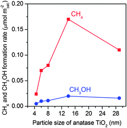 | ||
| Fig. 6 Effect of TiO2 particle sizes on the formation of CH4 and CH3OH in the photocatalytic reduction of CO2 with H2O.47 | ||
One-dimensional (1D) semiconductors have been synthesized and exploited for the photocatalytic reduction of CO2. For example, nitrogen-doped TiO2 nanotube arrays catalysed the photocatalytic reduction of CO2 with H2O vapour in the presence of Pt and/or Cu co-catalysts under outdoor sunlight irradiation.48 H2, CO and hydrocarbons (CH4 as well as small amounts of higher paraffins and olefins) were formed. The rate of hydrocarbon formation reached 150 μL g−1 h−1 under outdoor sunlight, even higher than those reported for Pt/TiO2 under UV illumination. The doping of nitrogen could extend the light absorption to the visible region. It was proposed that the thinner wall of the nanotube morphology could facilitate the transfer of the photogenerated carriers to the surface.
Zou and co-workers reported a series of 1D composite metal oxide semiconductors for the photocatalytic reduction of CO2 with H2O.49–55 For example, they synthesized Zn2GeO4 nanoribbons and nanorods using a solvothermal method in ethylenediamine/water and a low-temperature solution-phase methods, respectively.49,50 These Zn2GeO4 samples with 1D morphology showed higher activities for CO and CH4 formation during the photocatalytic reduction of CO2 under UV-vis irradiation than that prepared by the conventional high-temperature solid-state reaction (SSR) method. The catalytic performance could be enhanced by further loading Pt and/or RuO2 as co-catalysts. A nitrogen-doped Zn2GeO4, i.e., Zn1.7GeN1.8O4, with nanosheave morphology, which contained numerous closely packed nanorods, was demonstrated to be capable of catalysing the formation of CH4 from CO2 under visible-light irradiation after loading Pt and RuO2 co-catalysts.51 The nitrogen doping enhanced the light absorption in the visible-light region. The apparent quantum yield of CH4 evolution for this catalyst at a wavelength of 420 ± 15 nm was measured to be 0.024%.51 Similarly, Cd2Ge2O6 and In2Ge2O7 nanowires in the presence of Pt and/or RuO2 co-catalysts also showed better catalytic performances for the photocatalytic reduction of CO2 to CH4 under UV-vis irradiation than their counterparts prepared by the SSR method.52,53 The higher photocatalytic activity of 1D semiconductors as compared to that of the SSR sample could be attributed to the following reasons: (1) the ultra-long dimensions in one direction may provide a sufficiently spacious transport channel for charge separation; (2) the 1D geometry may allow charge carriers to move rapidly from the interior to the surface to participate in surface reactions; (3) the decrease of the lateral dimensions to the nanoscale offers a high specific surface area and a high surface site density.
Zou and co-workers further succeeded in synthesizing vanadate-based visible-light responsive semiconductors, i.e., Na2V6O16 and Fe2V4O13, with nano-ribbon morphology.54,55 The band-gap energies of Na2V6O16 and Fe2V4O13 nanoribbons were 1.93 and 1.78 eV, respectively. These semiconductors possessed conduction-band edges more negative than the redox potential for the reduction of CO2 to CH4, thus being capable of catalysing the reduction of CO2 with H2O under visible-light illumination (Fig. 7). The rate of CH4 formation was 0.2–0.5 μmol g−1 h−1 over Pt- and RuO2-co-loaded Na2V6O16 or Pt-loaded Fe2V4O13 catalysts under visible light (λ ≥ 420 nm).54,55
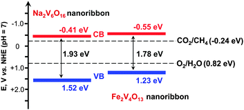 | ||
| Fig. 7 Band-edge positions of Na2V6O16 and Fe2V4O13 nanoribbons, two visible-light responsive photocatalysts for reduction of CO2 in the presence of H2O.54,55 | ||
Ye and co-workers synthesized ultra-thin W18O49 nanowires with diameters of ∼0.9 nm and found that this 1D material was efficient for the photocatalytic reduction of CO2 to CH4 under visible light (λ ≥ 420 nm) irradiation, whereas the commercial WO3 sample was completely inactive.56 The W18O49 nanowires showed strong absorption in visible and near infrared regions due to the oxygen vacancies. It was demonstrated that the activity decreased significantly when the density of oxygen vacancies was lowered by H2O2 treatment. Although the mechanism is still unclear, the presence of large amounts of oxygen vacancies should play crucial roles.
Two-dimensional (2D) semiconductors also showed unique catalytic behaviours for the photocatalytic reduction of CO2 with H2O. Ti0.91O2 nanosheets with lateral dimensions of 0.1–1 μm and a thickness of ∼0.75 nm have been synthesized for the photocatalytic reduction of CO2.57 The 2D Ti0.91O2 nanosheets provided CH4 as an exclusive product in the photoreduction of CO2. The rate of CH4 formation was 1.41 μmol g−1 h−1 under UV-vis irradiation on 2D Ti0.91O2. P25 provided CH4 and CO with rates of 0.69 and 0.16 μmol g−1 h−1, respectively, under the same conditions. The higher activity of Ti0.91O2 nanosheets probably arose from the more facile migration of photogenerated charge carriers onto the catalyst surface. The fabrication of hollow spheres consisting of molecular-scale alternating Ti0.91O2 nanosheets and graphene nanosheets by combining a layer-by-layer assembly technique and a microwave irradiation technique could further improve the photocatalytic performance. CO became a major product, and the rates of CH4 and CO formations were 1.14 and 8.91 μmol g−1 h−1, respectively, over the Ti0.91O2–graphene composite. The compact stacking of ultrathin Ti0.91O2 and graphene nanosheets may enable the transfer of the photogenerated electrons from Ti0.91O2 nanosheets to graphene rapidly, further enhancing the separation of charge carriers. Furthermore, the hollow structure might act as a photon trap to allow the multi-scattering of incident light, thus enhancing the light absorption.
Liang et al. investigated the effect of dimensionality of carbon nanomaterials on photocatalytic performances of nanocarbon–TiO2 composites for the reduction of CO2 with H2O.58 The comparative study revealed that the composite of 2D graphene and 2D TiO2 nanosheets showed better CH4 formation activity than the 1D–2D CNT–TiO2 nanosheet composite under UV illumination. This is likely attributable to the more intimate contact and superior electronic coupling in the 2D–2D graphene–TiO2 composite. On the other hand, 1D CNTs were demonstrated to be more effective photosensitizers, leading to better CH4 formation activity of the 1D–2D CNT–TiO2 nanosheet under visible-light illumination.58
Several studies have succeeded in synthesizing hierarchical structures consisting of semiconductor nanosheets or nanoplates for the photocatalytic reduction of CO2 with H2O. For example, uniform hierarchical ZnGa2O4 microspheres scaffolded from nanosheets with a thickness of ∼6 nm were found to be more efficient for CH4 formation than the mesoporous ZnGa2O4.59 A hexagonal nanoplate-textured micro-octahedron Zn2SnO4 showed higher CH4 formation activity than Zn2SnO4 atactic particles or micro-octahedra without hierarchical structure.60
Alkali and alkaline earth metal niobates and tantalates are attractive for the photocatalytic reduction of CO2 with H2O, since these semiconductors are not only stable and non-toxic but also possess excellent CO2 chemisorption abilities. Recent studies disclosed that these semiconductors also displayed significant morphological effects.61–63 For instance, KTaO3 nanoflakes synthesized by a solvothermal method in the hexane–H2O mixture were found to exhibit higher rates of CO and H2 formation in the photoreduction of CO2 with H2O than the cubic-like KTaO3 synthesized by the SSR method or by a similar solvothermal method but in a pure ethanol mixture.62 The higher surface area and the shorter charge-transfer pathway are believed to be responsible for the higher activity of the KTaO3 nanoflakes. We succeeded in synthesizing SrNb2O6 nanoplates with a thickness of ∼12 nm by a simple hydrothermal method.63 2D SrNb2O6 with nanoplate morphology showed higher CO and CH4 formation rates than SrNb2O6 with nanoparticulate morphology but with a similar specific surface area. The increased capability of electron–hole separation for the nanoplate was evidenced by the higher photocurrent density in the transient photocurrent response measurements. It was demonstrated that the SrNb2O6 nanoplate without any co-catalysts showed a higher rate for the production of (CO + CH4) (19.9 μmol g−1 h−1) than a 0.5 wt% Pt–TiO2 reference catalyst (6.9 μmol g−1 h−1) under UV-vis irradiation (λ = 300–780 nm).63 Moreover, the selectivity of the reacted electrons used for CO2 reduction with the SrNb2O6 nanoplate was much higher (82%) than that with the 0.5 wt% Pt–TiO2 (40%). This is probably because of the higher chemisorption ability of the SrNb2O6 nanoplate toward CO2.
Another interesting example of the morphological effect is the unique catalytic behaviour of 2D WO3 nanocrystals. Normally, the photogenerated electrons in the conduction band of WO3 could not be used for the reduction of CO2 or H2O due to the lower (more positive) band-edge position (Fig. 2). Almost no CH4 was formed during the photocatalytic reduction of CO2 with H2O over commercial WO3 microcrystals under visible-light irradiation.64 However, the ultra-thin 2D WO3 nanosheets with a thickness of 4–5 nm synthesized using a solid–liquid phase arc discharge method in an aqueous solution could catalyze the photoreduction of CO2 with H2O into CH4. The amount of CH4 was 16 μmol g−1 over the WO3 nanosheets under visible-light irradiation (λ > 420 nm) for 14 h.64 The WO3 nanosheets showed a significant blue shift in the UV-vis absorption spectrum as compared to the commercial WO3 probably due to the quantum-size effect. This increased the band-gap energy from 2.63 eV for the commercial WO3 microcrystals to 2.79 eV for the WO3 nanosheets. The edge of the conduction band of WO3 nanosheets was estimated to be −0.42 V (versus NHE), becoming more negative than the CO2/CH4 redox potential (−0.24 V) (Fig. 8). Thus, the reduction of CO2 to CH4 by the photogenerated electrons in the conduction band of WO3 nanosheets became feasible. The same phenomenon was observed by Xie et al., who successfully synthesized a quasi-cubic-like WO3 crystal with a nearly equal percentage of {010}, {200} and {020} facets, and a rectangular sheet-like WO3 crystal with a predominant {002} facet by controlling acidic hydrolysis of crystalline tungsten boride.65 The cubic-like WO3 was inactive for the photocatalytic reduction of CO2, whereas the sheet-like WO3 nanocrystals provided a CH4 formation rate of 0.34 μmol g−1 h−1 under visible-light (λ > 400 nm) irradiation.
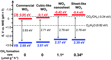 | ||
| Fig. 8 Effect of morphology of WO3 on the band-edge positions and the corresponding rates of CH4 formation for photocatalytic reduction of CO2 with H2O.64,65aRef. 64. bRef. 65. | ||
The elevated conduction-band edge was also proposed to contribute to CO2 reduction for the sheet-like WO3 nanocrystals (Fig. 8).65
Similarly, 2D Bi2WO6 could also be exploited for the photocatalytic reduction of CO2.66 Uniform Bi2WO6 square nanoplates with a thickness of ∼9.5 nm were synthesized using a hydrothermal method in the presence of oleylamine. This Bi2WO6 nanoplate possesses a band-gap energy of 2.75 eV with the conduction-band edge at −0.34 V (versus NHE), which is more negative than the CO2/CH4 redox potential (−0.24 V). The rate of CH4 formation was ∼1.1 μmol g−1 h−1 under visible-light illumination. Under the same conditions, Bi2WO6 synthesized by the SSR method was inactive.66
Recent studies have suggested that the controlled fabrication of semiconductor nanocrystals with preferentially exposed facets is an effective strategy to enhance the photocatalytic performance. For example, as mentioned above, the 2D Bi2WO6 nanoplate with dominant {001} facets exposed could catalyze the photocatalytic reduction of CO2, whereas Bi2WO6 synthesized by the SSR method was inactive.66 So far, more effort has been devoted to TiO2 nanocrystals to elucidate the effect of exposed facets on photocatalytic behaviours. Earlier work suggested that the {001} facet, the high-energy-surface of anatase, contributed more to photocatalysis.69–71 Cheng and co-workers found that 1D anatase TiO2 nanorods with dominant {010} facets exhibited a better photocatalytic performance for the reduction of CO2 into CH4 than P25.72 It has been clarified that the conduction-band edge is higher (more negative) for the {010}-dominant TiO2 nanorods. Moreover, the interactions of CO2 and H2O with {010} facets are stronger than {001} and {101} facets. These may contribute to the better catalytic performance of the {010} facet. In a subsequent work, the same group reported that hollow anatase TiO2 single crystals and mesocrystals with dominant {101} facets could efficiently catalyze the formation of CH4 from CO2 than solid TiO2 single crystals.73 It seems that the hollow structure plays a pivotal role in the photocatalytic reduction of CO2 probably because of the shortened bulk diffusion length of charge carriers.73 Ye and co-workers claimed that the TiO2 ultra-thin nanosheets, which has a thickness of ∼2 nm and exposed 95% {100} facets, showed better catalytic performance for the reduction of CO2 to CH4 than TiO2 cuboids with 53% {100} facets exposed.74 These discrepancies suggest that the direct comparison of catalysts with different preferentially exposed facets should be careful because the parameter other than the exposed facet may be the determining factor.
A recent study compared the photocatalytic activities of anatase TiO2 nanocrystals with different exposed low-index facets, i.e., {001} (nanoplate), {101} (nano-octahedron) and {010} (nanorod), for the reduction of CO2 with H2O to CH4 in the vapour phase.75 The percentage of each kind of facets in the synthesized TiO2 nanocrystals reached 90%. The activity for photoreduction of CO2 to CH4 was found to decrease in the order of {010} > {101} > {001} (Fig. 9). The result that the 1D nanorod TiO2 exhibited the highest CH4 formation rate is in agreement with that reported by Cheng and co-workers.72 The order, however, was found to be completely different from that for the degradation of rhodamine B in water.75 The photoluminescence (PL) spectroscopic study clarified that the ability of electron–hole separation decreased in the order of {010} < {101} < {001}. Thus, although the nanoplate TiO2 with 90% {001} facets favours the electron–hole separation, this sample is less efficient for photocatalytic reduction of CO2. Further analyses revealed that the conduction-band edge position became more negative in the order of {010} > {101} > {001}, suggesting that the reduction power of the photogenerated electrons is the highest for the {010} facet. Moreover, the {010} facet was more active for CO2 chemisorption in the presence of H2O. Thus, it seems that the reduction power of electrons and the CO2 chemisorption capability rather than the electron–hole separation ability mainly determine the catalytic performance for CO2 reduction.
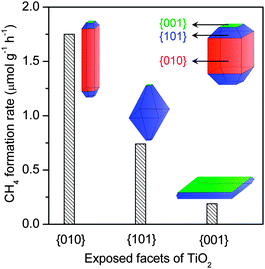 | ||
| Fig. 9 Comparison of photocatalytic activity of TiO2 nanocrystals with different preferentially exposed facets for photocatalytic reduction of CO2 with H2O to CH4.75 | ||
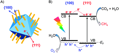
Recently, the co-existence of {001} and {101} facets with a appropriate ratio in a TiO2 nanocrystal has been proposed to favour the photocatalytic reduction of CO2 with H2O.76,77 Anatase TiO2 nanocrystals have typically truncated octahedral bipyramid morphology, which comprises eight {101} facets on sides and two {001} facets on the top and bottom (see the inset in Fig. 10).69,77 By an addition of HF into the synthetic system, the ratio of {001}/{101} or the fraction of {001} facets increased and the morphology changed gradually to the nanoplate due to the stabilizing role of F−.69,76,77 By studying the photocatalytic reduction of CO2 with H2O in a solid–liquid reaction mode containing NaOH in aqueous solution, He et al. found that the TiO2 nanocrystal with a {001}/{101} ratio of ∼72![[thin space (1/6-em)]](https://www.rsc.org/images/entities/char_2009.gif) :
:![[thin space (1/6-em)]](https://www.rsc.org/images/entities/char_2009.gif) 28 showed the highest activity.76 Yu and co-workers performed a detailed comparison of a series of TiO2 nanocrystals with different {001} fractions for the photocatalytic reduction of CO2 with H2O vapour.77 The results showed that the rate of CH4 formation increased significantly upon increasing the fraction of {001} facets from 11% to 58% and then decreased with a further increase in the fraction of {001} facets (Fig. 10A). The highest CH4 formation rate over the nanocrystal with a {001}/{101} ratio of 58/42 was 1.35 μmol h−1 g−1. To explain the existence of an optimum ratio of {001}/{101}, Yu and co-workers proposed a “surface or facet junction” concept.77 On the basis of DFT calculations, the conduction-band and valance-band edges of {001} and {101} facets are slightly different (Fig. 10B), and a facet junction could be formed because the {001} and {101} facets contact each other in the nanocrystal. The photogenerated electrons and holes can thus migrate to {101} and {001} facets, respectively, during a photocatalytic process. Therefore, the {101} facet plays a role in the reduction of CO2 to CH4, while the {001} facet plays a role in the oxidation of H2O to O2. The facet junction would thus enhance both the separation of electron–hole pairs and the reduction–oxidation reactions. It is easy to understand that the co-existence of {001} and {101} facets plays a crucial role in the photocatalytic reduction of CO2 and there is an optimum ratio of the two facets because of the key role of the facet junction between the two facets.
28 showed the highest activity.76 Yu and co-workers performed a detailed comparison of a series of TiO2 nanocrystals with different {001} fractions for the photocatalytic reduction of CO2 with H2O vapour.77 The results showed that the rate of CH4 formation increased significantly upon increasing the fraction of {001} facets from 11% to 58% and then decreased with a further increase in the fraction of {001} facets (Fig. 10A). The highest CH4 formation rate over the nanocrystal with a {001}/{101} ratio of 58/42 was 1.35 μmol h−1 g−1. To explain the existence of an optimum ratio of {001}/{101}, Yu and co-workers proposed a “surface or facet junction” concept.77 On the basis of DFT calculations, the conduction-band and valance-band edges of {001} and {101} facets are slightly different (Fig. 10B), and a facet junction could be formed because the {001} and {101} facets contact each other in the nanocrystal. The photogenerated electrons and holes can thus migrate to {101} and {001} facets, respectively, during a photocatalytic process. Therefore, the {101} facet plays a role in the reduction of CO2 to CH4, while the {001} facet plays a role in the oxidation of H2O to O2. The facet junction would thus enhance both the separation of electron–hole pairs and the reduction–oxidation reactions. It is easy to understand that the co-existence of {001} and {101} facets plays a crucial role in the photocatalytic reduction of CO2 and there is an optimum ratio of the two facets because of the key role of the facet junction between the two facets.
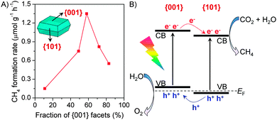 | ||
| Fig. 10 (A) Effect of fraction of {001} facets in anatase TiO2 nanocrystals with octahedral bipyramid morphology on the photocatalytic conversion of CO2 with H2O to CH4.77 (B) Illustration of the facet junction between {001} and {101} facets.77 | ||
Very recently, CeO2 with co-exposed {100} and {111} facets has been demonstrated to favour the photocatalytic CO2 reduction.78 Hexahedron-prism anchored CeO2 octahedra with {100} facets on the prism and {111} facets on the octahedron (Fig. 11A) were successfully synthesized by Zou and co-workers.78 CeO2 octahedra without hexahedron-prism anchored were inactive possibly because of the rapid recombination of photogenerated electrons and holes on the {111} facet. The anchoring of CeO2 hexahedron-prisms significantly increased the photocatalytic activity for the reduction of CO2 with H2O to CH4. The highest rate of CH4 formation over Pt- and MnOx-co-loaded hexahedron-prism anchored octahedron CeO2 was 1.12 μmol g−1 h−1, and the molar ratio of CH4/O2 was close to the stoichiometric ratio (1/2). Computational studies showed slight differences in the positions of the conduction-band and valance-band edges between {100} and {111} facets, suggesting the formation of a facet junction (Fig. 11B). This would accelerate the separation of electron–hole pairs, and thus enhance the photocatalytic performance for CO2 reduction.
The composite semiconductor could form heterojunctions between different components at the interface and such a heterojunction may result in significant synergistic effects mainly because of the enhanced charge separation. Typically, the charge transfer between different components in a composite may proceed via three mechanisms, i.e., sensitization, p–n junction and Z-scheme mechanisms (Fig. 12). In the sensitization mechanism (Fig. 12A), the photogenerated electrons are transferred from the conduction-band of a narrow bandgap semiconductor (e.g., PbS or C3N4) to that of a wide-bandgap semiconductor (e.g., TiO2 or NaNbO3). This is an effective way to realize the photoreduction of CO2 under visible light irradiation.79,80 The formation of a p–n junction between two components with proper band-edge positions could significantly promote the charge separation (Fig. 12B). Many composites such as ZnO–TiO2, NiO–TiO2 and CuO–TiO2−xNx with such a type of heterojunction have been demonstrated to be efficient for the photocatalytic reduction of CO2 to CH4 with H2O.81,82 Photocatalytic systems with Z-scheme heterojunctions (Fig. 12C), which mimic the natural photosynthetic process, have also been constructed for photoreduction of CO2 with H2O. For example, Fan and co-workers fabricated Ag3PO4/g-C3N4 composites, which were believed to function with the Z-scheme mechanism for photocatalytic reduction of CO2.83 The catalyst with an Ag3PO4/g-C3N4 molar ratio of 3/10 showed a CO2 conversion rate of 57.5 μmol g−1 h−1, which were 6.1 and 10.4 times larger than pure g-C3N4 and P25, respectively.83
2.3 Effect of noble or coinage metal or metal oxide co-catalysts on photocatalytic reduction of CO2 with H2O
| Photocatalyst | Formation rate (μmol g−1 h−1) | Light source | Ref. |
|---|---|---|---|
| Effect of noble or coinage metal or metal oxide cocatalysts | |||
| Ag/BaLa4Ti4O15 (Ag: <10 nm) | CO: 63 | Hg lamp | 84 |
| 1.0 nm Pt/TiO2 thin film | CH4: 1361 | Xe lamp | 87 |
| Cu0.33–Pt0.67/TiO2 | Hydrocarbons: 3.73 mL g−1 h−1 | UV lamp (365 nm) | 88 |
| Pt@Cu2O/TiO2 | CH4: 33, CO: 8.3, H2: 25 | Xe lamp (320–780 nm) | 89 |
| 1 wt% Cu2O/TiO2-{001} | CH4: 8.7 | Xe lamp | 90 |
| Ni@NiO/N-doped InTaO4 | CH3OH: 160 | Xe lamp (390–770 nm) | 91 |
| Au0.33–Cu0.67/TiO2 thin film | CH4: 2200, H2: 286 | Xe lamp | 92 |
| Au0.75–Cu0.25/SrTiO3/TiO2 NT | CH4: 1.9 ppm cm−2 h−1 | Xe lamp | 93 |
| Au0.25/Pt0.75/TiO2 NFs | CH4: 114 | Xe lamp (UV-vis) | 94 |
| Effect of cocatalysts enhancing CO2 adsorption | |||
| MgO–TiO2 microspheres | CO: 21 (150 °C), 2 (50 °C) | Xe lamp (200–1000 nm) | 97 and 98 |
| 0.5% Pt–1.0% MgO/TiO2 | CH4: 11, CO: 0.03, H2: 11 | Xe lamp (320–780 nm) | 32 and 99 |
| P25 | CH4: 0.38, CO: 1.2, H2: 2.1 | ||
| 3% NaOH modified TiO2 | CH4: 8.7, H2: 19 | Xe lamp | 100 |
| NH2-MIL-125(Ti) | HCOOH: 16 | Xe lamp (420–800 nm) | 101 |
| ZIF-8/Zn2GeO4 nanorods | CH3OH: 2.3 | Xe lamp | 102 |
| MEA-functionalized TiO2 | CH4: 8.6 ppm h−1, CO: 67 ppm h−1 | Xe lamp (UV-vis) | 103 |
| Pt–0.85% PANI–TiO2 | CH4: 50, H2: 320 | Xe lamp (UV-vis) | 104 |
| Pt–TiO2 | CH4: 15, H2: 113 | ||
We have compared the catalytic performances of TiO2 doped with different noble or coinage metal co-catalysts, including Pt, Pd, Rh. Au and Ag, for the photocatalytic reduction of CO2 with H2O vapour.32 These co-catalysts accelerated the formation of CH4. The formation of CO was, however, not significantly enhanced. The rate of CH4 formation increased in the order of Ag < Au < Rh < Pd < Pt. This sequence is the same with that of the work function of metals, suggesting that the metal co-catalyst mainly functions for the extraction of electrons from TiO2. This was further supported by the transient photocurrent response measurements. Thus, Pt was the most efficient co-catalyst to enhance the CH4 formation owing to its highest ability to separate the photogenerated electron–hole pairs. In addition to CH4, the formation of H2 was also accelerated in the presence of Pt or other noble metal cocatalysts. Generally, the selectivity of the reacted electrons for CO2 reduction was rather decreased due to the presence of a noble or coinage metal cocatalyst.
For some semiconductor photocatalysts with CO as the major reduction product, different trends were observed for the effect of noble or coinage metal co-catalysts. For example, Kudo and co-workers found that Ag was the most active co-catalyst for the reduction of CO2 to CO over a BaLa4Ti4O15 semiconductor, although the amount of the reacted electrons decreased in the order of Au > Rh > Cu > Ag.84 The addition of Ag onto KTaO3 nanoflakes was also found to accelerate the photocatalytic reduction of CO2 to CO.62 At the same time, the rate of H2 formation was decreased, and thus the selectivity of the reacted electrons for CO2 reduction increased by using Ag as a co-catalyst. On the other hand, the addition of Pt rather decreased the formation of CO over the KTaO3 catalyst. Pt is not an efficient co-catalyst for CO formation because of the poisoning effect of chemisorbed CO. Studies on electrochemical reduction of CO2 showed that Pt was not a suitable electrocatalyst for CO formation because CO is bound to Pt too tightly, whereas Ag and Au were efficient electrocatalysts for the reduction of CO2 to CO.85,86 Thus, the major role of Ag may be its function in providing active sites to catalyze the following reaction:
| CO2 + 2H+ + 2e− → CO + H2O |
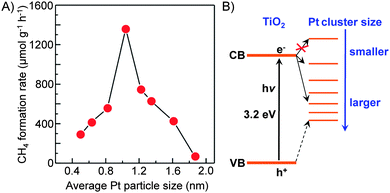 | ||
| Fig. 13 Effect of size of Pt nanoclusters loaded on TiO2 nanofilms on the rate of CH4 formation from CO2 and the proposed energy levels.87 | ||
Kudo and co-workers found that the activity of Ag/BaLa4Ti4O15 for photocatalytic reduction of CO2 to CO depended on the method to load Ag nanoparticles.84 The work not only confirmed the importance of the size of Ag particles but also demonstrated the role of unique location of Ag nanoparticles on the working catalyst. BaLa4Ti4O15 had a plate morphology with ∼100 nm thickness and ∼1 μm width. During the photodeposition process, Ag particles with sizes of 30–40 nm were predominantly loaded on the edge of the plate. On the other hand, Ag particles could be loaded on both edge and basal planes of BaLa4Ti4O15 by a chemical reduction method. It is of interest that the Ag particles on the basal plane can be dissolved by photogenerated holes and re-photodeposited again on the edge during the photocatalytic reaction (Fig. 14). The sizes of re-photodeposited Ag particles on the edge were smaller than 10 nm and were more uniform than the Ag particles directly photodeposited from the aqueous solution with high concentration of Ag+. The re-photodeposition was also observed in the case of the sample prepared by impregnation followed by H2 reduction, and the sizes of Ag re-photodeposited were 10–20 nm. The sizes of Ag nanoparticles on the edge plane of BaLa4Ti4O15 under working conditions were in the sequence of liquid-phase reduction < impregnation and H2 reduction < photodeposition, whereas the CO formation rate changed in an opposite sequence. Thus, the smaller size of Ag nanoparticles on the working catalyst showed higher activity of CO formation. The reduction of CO2 to CO mainly occurred on the Ag nanoparticles loaded on the edge of the BaLa4Ti4O15 plate, whereas the oxidation of H2O to O2 occurred on the basal plane (Fig. 14). The unique location of Ag nanoparticles on the working catalyst led to the separation of the reduction and oxidation reactions on different planes (Fig. 14), and thus would increase the activity for the photocatalytic CO2 reduction with H2O.
 | ||
| Fig. 14 The re-deposition of Ag nanoparticles on the edge of BaLa4Ti4O15 during the photocatalytic reduction of CO2 with H2O.84 Photogenerated electrons mainly go to the edge plane, while the photogenerated holes mainly go to the basal plane. The Ag nanoparticles on the basal plane were dissolved by the holes. | ||
A few groups have investigated the catalytic behaviours of TiO2-promoted with Pt and Cu binary co-catalysts.48,88,89 For example, Grimes and co-workers found that Cu nanoparticles loaded on nitrogen-doped TiO2 nanotube (NT) arrays efficiently catalyzed the formation of hydrocarbons (mainly CH4 as well as small amounts of C2–C6 paraffins and olefins) and CO from CO2 and H2O under sunlight illumination.48 Pt-promoted NTs could also catalyze the formation of hydrocarbons, but more H2 was formed on Pt-NT. The co-loading of Cu and Pt on NTs in different places caused the simultaneous formation of hydrocarbons and H2 with large amounts, although the rate of hydrocarbon formation was not significantly accelerated. These results indicated that Pt and Cu nanoparticles on NTs were the active centers for the reduction of H2O and CO2, respectively.
Bimetallic Cu and Pt cocatalysts loaded on periodically modulated double-walled TiO2 nanotube (PMTiNT) arrays were investigated for the photocatalytic reduction of CO2 with H2O under illumination using a solar simulator.88 CH4, C2H4 and C2H6 were obtained as the major hydrocarbon products and the formation rate reached 3.73 mL g−1 h−1 for the reduction of diluted CO2 (0.998% CO2) over a Cu0.33–Pt0.67/PMTiNT catalyst. In addition to the role of the increased surface area and improved light absorption due to PMTiNT, the bimetallic co-catalysts played key roles in increasing the catalyst activity. However, the nature of the synergistic effect between Pt and Cu was not discussed in depth.
We found that the addition of Pt onto TiO2 (P25) could enhance the formation of H2 more significantly than that of CH4, and thus the selectivity of the reacted electrons for CO2 reduction decreased.32 On the other hand, the use of Cu as a co-catalyst increased the rate of CH4 formation more than that of H2 formation, although the total amount of reacted electrons was lower than that in the case of Pt. It was unexpected that the Pt–Cu/TiO2 catalyst, which was prepared by a chemical reduction method using hydrazine as a reductant and was composed of Pt and Cu2O nanoparticles, did not show any synergistic effects for CH4 formation.89 On the other hand, the Cu/Pt/TiO2 catalyst, which was prepared by a stepwise photodeposition technique, showed a significantly enhanced CH4 formation rate. The characterization using XPS, AES and high-sensitivity low-energy ion scattering (HS-LEIS) spectroscopy, which is known to be a powerful technique to detect the outermost composition of surfaces, suggested the formation of a core–shell structure of Pt@Cu2O in the Cu/Pt/TiO2 catalyst with a proper Cu content. The Cu content in the catalyst could be regulated by varying the irradiation time during the photodeposition of Cu onto Pt/TiO2. The increase in the Cu content deposited onto 0.9 wt% Pt/TiO2 to 1.7 wt% significantly increased the rates of CH4 and CO formation and decreased that of H2 formation (Fig. 15A). Thus, the selectivity of reacted electrons for CO2 reduction increased significantly at the same time. The characterization revealed that the Pt@Cu2O core–shell structure was formed when the Cu content reached 1.7 wt%, and a further rise in the Cu content increased the thickness of the Cu2O shell. The maximum rates of CH4 and CO formation were obtained over the Cu/Pt/TiO2 catalyst with a Cu content of 1.7 wt%, being 33 and 8.3 μmol g−1 h−1, respectively. These results indicate that the Cu2O shell provides sites for the activation and reduction of CO2, whereas the Pt core mainly works for the extraction of photogenerated electrons from TiO2 (Fig. 15B). A recent study investigated the catalytic behaviour of Cu2O photodeposited on TiO2 {001} facets.90 The result confirmed that Cu2O was the active phase for the chemisorption of CO2 and the formation of CH4 through the photogenerated electrons and H species. In our case, the Cu2O shell on the Pt core could also suppress the reduction of H2O by the photogenerated electrons (Fig. 15B), which can occur facilely on Pt surfaces. Furthermore, the transient photocurrent response measurements revealed that the ability of Pt to separate electron–hole pairs was not significantly affected by covering it with the Cu2O shell.89
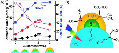 | ||
| Fig. 15 (A) Changes of product formation rates with Cu content.89 (B) Proposed functioning mechanisms of Cu2O and Pt co-catalysts on TiO2 surfaces for conversion of CO2 into CH4 and CO.89 Adapted from ref. 89 with permission from Wiley. | ||
A Ni@NiO core–shell structured co-catalyst loaded on N-doped InTaO4 (InTaO4-N) probably worked in a similar way to the Pt@Cu2O cocatalyst.91 The metallic Ni in the core may be responsible for trapping the electrons, while NiO on the shell worked as the active site for CO2 activation and reduction. The formation of CH3OH was detected over the Ni@NiO/InTaO4-N catalyst during the photocatalytic reduction of CO2 with H2O in the liquid phase under visible light (λ = 390–770 nm) irradiation.
Two subsequent studies demonstrated that Au–Cu alloy particles were also efficient binary co-catalysts for the photocatalytic reduction of CO2.92,93 Au–Cu alloy nanoparticles loaded on TiO2 thin films showed high activity for the photocatalytic reduction of CO2 with H2O under sun-simulated light. The rate of CH4 formation could exceed 2 mmol g−1 h−1.92 The selectivity of the reacted electrons for CH4 formation reached 97%. On the other hand, the Au/TiO2 and Cu/TiO2 catalysts showed either lower selectivity or lower activity. The alloy nanoparticles were proposed to account for the synergistic effect observed for CH4 formation. Although the in-depth functioning mechanism of the alloy is still unclear, it seems that the presence of Cu contributes to the high CO2 selectivity, whereas the surface plasmon band of Au may induce the visible-light photo-response and thus accelerate the activity under sun-simulated light. The Au–Cu binary alloy was also an efficient co-catalyst for the photocatalytic reduction of CO2 with hydrous hydrazine over SrTiO3/TiO2 coaxial nanotube arrays.93 Under the irradiation of UV-vis light, the reduction of diluted CO2 (33.3% in Ar) with hydrous hydrazine provided CO and hydrocarbons with rates of 3.77 and 0.725 mmol g−1 h−1, respectively, over a Au3Cu alloy-promoted SrTiO3/TiO2 coaxial nanotube array.93
Several other studies have demonstrated Au- or Ag-containing bimetallic co-catalysts for photocatalytic reduction of CO2 with H2O.94,95 Au and Ag are known to be capable of absorbing visible light due to their surface plasmon resonance (SPR) effect. For example, Zhang et al. loaded both Au and Pt nanoparticles onto TiO2 nanofibers by an electrospinning technique.94 The Au0.25/Pt0.75/TiO2 nanofiber catalyst exhibited higher activity for CH4 formation (0.57 μmol h−1) than the Pt/TiO2 (0.42 μmol h−1) and Au/TiO2 (0.31 μmol h−1) catalysts under UV-vis irradiation. The enhanced photocatalytic behaviour could be attributable to both the electron-trapping effect of Pt nanoparticles and the SPR effect of Au nanoparticles (Fig. 16). Gupta and co-workers found a significant enhancement in the photocatalytic reduction of CO2 with H2O to CH4 by co-loading Ag–Pt bimetallic nanoparticles and core–shell Ag@SiO2 particles onto TiO2.95 Ag@SiO2 improved the activity of TiO2 primarily by the SPR effect, while the Ag–Pt co-catalysts should contribute to trapping of electrons and accelerating the transfer of electrons to CO2 for reduction.
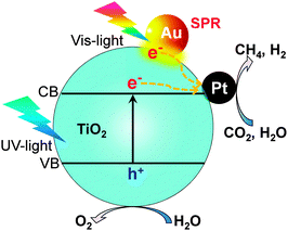 | ||
| Fig. 16 Photocatalytic reduction of CO2 with H2O over Au- and Pt-co-loaded TiO2 nanofibers possibly with the surface plasmon resonance effect.94 | ||
The combination of reduction and oxidation co-catalysts has been demonstrated to be helpful in enhancing the water splitting reactions.96 Noble metals such as Pt and Pd have mainly been employed as reduction cocatalysts, while metal oxides such as RuO2 CoOx and MnOx have been exploited as oxidation co-catalysts. A few groups have studied the role of the co-existence of reduction and oxidation co-catalysts in the photocatalytic reduction of CO2 with H2O. For instance, Zou and co-workers reported that the Pt and RuO2 co-catalysts, which were simultaneously loaded on the Zn1.7GeN1.8O, Cd2Ge2O7, In2GeO7 or Zn2SnO4 semiconductor, exhibited synergistic effects for photocatalytic reduction of CO2 with H2O to CH4.51–53,60 Pt and RuO2 were proposed to trap the electrons and holes, and to provide active sites for the reduction of CO2 and oxidation of H2O, respectively.
2.4 Effect of co-catalysts enhancing CO2 adsorption on photocatalytic reduction of CO2 with H2O
We found that the addition of MgO onto TiO2 could enhance the rate of CO formation during the photoreduction of CO2 with H2O vapour at ambient temperature, but the degree of enhancement was very limited.99 However, a significant enhancement in CH4 formation was observed by addition of MgO into Pt–TiO2. In addition to MgO, many basic metal oxides exhibited positive effects in promoting the rate of CH4 formation. A recent study showed that the addition of NaOH or Na2CO3 onto TiO2 also enhanced the rate of CH4 formation even in the absence of a noble metal co-catalyst such as Pt.100 We observed a linear relationship between the rate of CH4 formation and the amount of CO2 chemisorption on the surfaces of a series of basic metal oxide-promoted Pt–TiO2 catalysts (Fig. 17). This clearly demonstrates that the basicity, i.e., the ability to chemisorb CO2, plays crucial roles in the photocatalytic reduction of CO2 with H2O vapour to CH4 and that the co-existence of Pt and a basic metal oxide is a key.
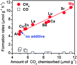 | ||
| Fig. 17 Effect of basic metal oxide co-catalysts on the catalytic behaviours of Pt–TiO2 catalysts for the photocatalytic reduction of CO2 with H2O vapour.99 Reproduced from ref. 99 with permission from Royal Society of Chemistry. | ||
Further studies on the trinary MgO–Pt–TiO2 catalysts clarified that MgO existed as an amorphous layer on TiO2 and Pt was mainly loaded on the interface between MgO and TiO2. The optimum content of MgO for CH4 formation was 1.0 wt% for the MgO–Pt–TiO2 catalyst with a Pt content of 0.5 wt% (Fig. 18A).32 A larger content of MgO decreased the rate of CH4 formation. It is of interest that the rate of H2 formation decreased significantly upon increasing the content of MgO. Thus, the selectivity of the reacted electrons for CO2 reduction increased from ∼40% for the Pt–TiO2 to ∼80% for the 1.0 wt% MgO–0.5 wt% Pt–TiO2 catalyst (Fig. 18B). The transient photocurrent response measurements clarified that the photocurrent density decreased by the addition of MgO into Pt–TiO2 and such a decrease in photocurrent density became more significant when the content of MgO was >1.0 wt% (Fig. 18B). This suggests that the excess amount of MgO on TiO2 may act as an insulating layer and retard the transfer of photogenerated electrons to Pt nanoparticles, thus hindering the separation of electron–hole pairs. Therefore, we propose that, compared to Pt–TiO2, on which the reduction of H2O proceeded more facilely (Fig. 18C), the presence of MgO can work for enhancing the chemisorption of CO2 onto catalyst surfaces and the chemisorbed CO2 can be reduced by the electron trapped on the nearby Pt nanoparticles (Fig. 18D). The interface among Pt, MgO and TiO2 is the key to the synergistic effect.
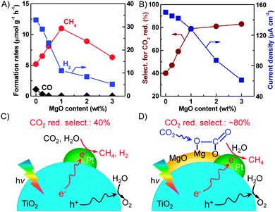 | ||
| Fig. 18 (A) Effect of MgO content on the product formation rates. (B) Effect of MgO content on the selectivity for CO2 reduction and the current density. (C) Proposed functioning mechanism of the Pt–TiO2 catalyst. (D) Proposed functioning mechanism of the MgO–Pt–TiO2 catalyst.32,99 | ||
The modification of semiconductors with basic organic amines is another useful strategy to enhance the chemisorption of CO2. Xue and co-workers prepared an amine-functionalized TiO2 through a solvothermal process by performing a reaction between TiCl4 and monoethanolamine (MEA) in ethanol at 473 K.103 The amount of CO2 adsorption on the MEA-functionalized TiO2 (MEA–TiO2) was much higher than that on TiO2 or hydroxyl-functionalized TiO2 (EG–TiO2). In the photocatalytic reduction of CO2 with H2O vapour, MEA–TiO2 provided CO and CH4 with rates of 67 and 8.6 ppm h−1, respectively, which were significantly larger than those on TiO2 and EG–TiO2.
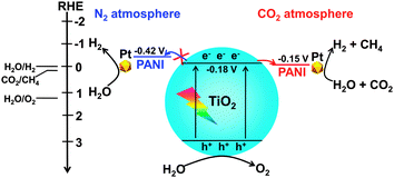
Polyaniline (PANI), a conducting polymer composed of benzenoid and quinonoid units, is attractive as a co-catalyst for photocatalysis because of its high mobility of charge carriers, good stability, non-toxicity and ease of synthesis. PANI is expected to play a unique role in CO2 photoreduction, since the combination of PANI with a semiconductor may not only enhance the transfer of photogenerated carriers but also may increase the chemisorption of CO2 due to the nitrogen-containing functional groups in PANI. We recently confirmed the promoting effect of PANI on the catalytic performance of TiO2 (P25) for the photocatalytic reduction of CO2 with H2O vapour.104 The PANI–TiO2 nanocomposite was synthesized by an in situ oxidative polymerization method. The characterization revealed that PANI was located on the TiO2 surface as amorphous film and the thickness of the PANI film increased from 2.5 to 8.0 nm, corresponding to 5–16 single molecular layers, upon increasing the PANI content from 0.17 to 4.1 wt%. Pt nanoparticles with a content of 0.5 wt% were also loaded onto the PANI–TiO2 nanocomposite. CH4, CO and H2 were mainly formed over the PANI–TiO2 and Pt–PANI–TiO2 nanocomposites. The introduction of PANI with a proper content significantly enhanced the rates of product formation. CH4 and CO were not formed or only formed with a trace amount by using N2 instead of CO2, indicating that CH4 and CO were formed predominantly by the reduction of CO2. H2 was a major reduction product in the absence of CO2. It is of interest that the presence of CO2 significantly enhanced the rate of H2 formation over the PANI–TiO2 and Pt–PANI–TiO2 nanocomposites, whereas the rate of H2 formation was almost the same in the presence and the absence of CO2 over TiO2 and Pt–TiO2 without PANI modification (Fig. 19). In other words, the presence of CO2 not only results in the formation of CH4 and/or CO but also accelerates the reduction of H2O to H2 uniquely over the catalyst containing PANI.
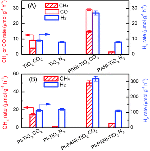 | ||
| Fig. 19 Comparison of rates of CH4, CO and H2 formations under CO2 and N2 atmospheres.104 (A) TiO2 and 0.85% PANI–TiO2. (B) Pt–TiO2 and Pt–0.85% PANI–TiO2. Reaction conditions: catalyst, 0.010 g; CO2 or N2 pressure, 0.20 MPa; light source, 320–780 nm; irradiation time, 4 h. Reproduced from ref. 104 with permission from Royal Society of Chemistry. | ||
Deep studies were performed to understand the unique phenomenon that the presence of CO2 accelerates the reduction of H2O to H2 for the PANI-containing catalyst. The addition of an acid such as HCl is known to be capable of increasing the conductivity of PANI dramatically.105 It can thus be considered that the conductivity of the PANI-containing catalysts may also be enhanced through the interaction with CO2, an acidic molecule, thus favouring the electron transfer and electron–hole separation. Further studies clarified that the presence of CO2 increased the current density in the transient photocurrent response measurement for the PANI-containing catalyst, whereas such an enhancement was not observed for the catalyst without PANI. Electrochemical impedance spectroscopy showed that the electron-transfer resistance was significantly decreased for the PANI-containing catalysts under a CO2 atmosphere. Photoluminescence spectroscopy further confirmed that the luminescence band arising from the electron–hole recombination was suppressed for the PANI-containing catalyst by switching the gas atmosphere from N2 to CO2. Mott–Schottky measurements indicated that TiO2 under both N2 and CO2 atmospheres had the same LUMO level or conduction-band edge of −0.18 V (vs. RHE, reversible hydrogen electrode), whereas the LUMO level of PANI changed from −0.42 V (vs. RHE) to −0.15 V (vs. RHE) by switching the atmosphere from N2 to CO2. Thus, the transfer of electrons from the conduction band of TiO2 to PANI becomes feasible under a CO2 atmosphere owing to the change in the LUMO level of PANI (Fig. 20). This would contribute to the enhancement in the separation of photogenerated electron–hole pairs in the PANI-containing catalyst under CO2, thus resulting in higher photocatalytic performances for the formation of CH4 and H2 from CO2 and H2O.
3. Photoelectrocatalysis
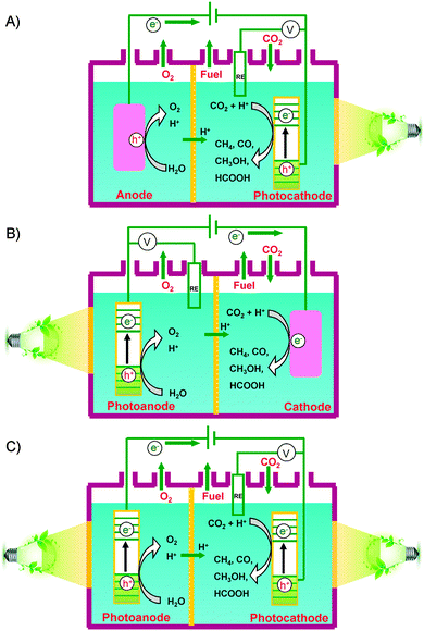
Besides the photocatalytic reduction of CO2, electrocatalysis and photoelectrocatalysis are also promising methods to achieve the reduction of CO2 into fuels and chemicals such as hydrocarbons, oxygenates or CO. Electrocatalysis requires a large amount of electricity to overcome the high energy barrier for CO2 reduction. Photoelectrocatalysis is similar to electrocatalysis with regard to the experimental setup. However, photoelectrocatalysis integrates photocatalysis with electrocatalysis and typically exploits semiconductor electrodes instead of normal conducting electrodes used in electrocatalysis. Photoelectrocatalytic reduction of CO2 would reduce electricity consumption as compared to the electrocatalytic reduction of CO2 because of the introduction of solar energy. On the other hand, as compared to photocatalysis, photoelectrocatalysis may achieve higher efficiency because the applied external bias voltage can drive the separation of photogenerated electrons and holes, which is the most crucial step in limiting the photocatalytic efficiency.In a typical photoelectrocatalytic setup, a semiconductor absorbs the light to promote the reactions on the surfaces of electrodes. Fig. 21 shows schematic illustrations of three typical two-compartment photoelectrocatalytic cells separated by proton exchange membranes. Semiconductors may be used as either photocathodes (Fig. 21A) or photoanodes (Fig. 21B). Both electrodes can also employ semiconductor photocatalysts (Fig. 21C). Take Fig. 21C as an example. Both electrodes absorb light to generate electrons and holes. The holes generated at the photoanode (typically an n-type semiconductor) may oxidize H2O to O2, while the photogenerated electrons at the photocathode (typically a p-type semiconductor) may work for the reduction of CO2 to CO, HCOOH, methanol or hydrocarbons in the presence or absence of a co-catalyst. Fig. 22 displays a schematic energy-band edge position requirement for the two semiconductors to perform the reduction and oxidation reactions. The photogenerated electrons may be transferred through an external wire from the photoanode to the photocathode, favouring the efficiencies of both reduction and oxidation reactions. The development of efficient photocathodes and/or photoanodes with proper energy-band edges and ability to activate CO2 molecules is the key to obtaining high efficiencies for the photoelectrocatalytic reduction of CO2. Table 5 summarizes some recently reported systems with the three different types of photoelectrocatalytic cells for the reduction of CO2.
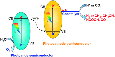 | ||
| Fig. 22 Scheme of a full photoelectrocatalytic cell coupling H2O oxidation (photoanode semiconductor) and CO2 reduction (photocathode semiconductor with a co-catalyst). | ||
| Electrode | Efficiencya | Conditionsb | Ref. |
|---|---|---|---|
| a Including reduction product amounts, concentrations or rates and Faradaic efficiency (FE). b Including electrolyte, applied potential, reaction time and light source. | |||
| Type A: photocathode + anode | |||
| (1) No co-catalyst | |||
|
Photocathode: p-GaP
Anode: carbon rod |
HCOOH: 50 mM
HCHO: 0.28 mM CH3OH: 0.81 mM |
K2HPO4/KH2PO4, −1.0 V vs. SCE, 90 h, Hg lamp | 27 |
| (2) Metal complex co-catalyst | |||
|
Photocathode: Ru complex modified Zn-doped p-InP
Anode: glassy carbon |
HCOOH: 0.17 mM
FE: 62% |
Pure water, −0.6 V vs. Ag/AgCl, 3 h, visible light | 107 |
|
Photocathode: Ru complex polymer modified Cu2ZnSnS4
Anode: glassy carbon |
HCOOH: 0.49 mM
FE: 80% |
Pure water, −0.4 V vs. Ag/AgCl, 3 h, visible light | 108 |
|
Photocathode: p-Si + Re(bipy-tBu)(CO)3Cl
Anode: Pt electrode |
H2 + CO (H2/CO = 2![[thin space (1/6-em)]](https://www.rsc.org/images/entities/char_2009.gif) : :![[thin space (1/6-em)]](https://www.rsc.org/images/entities/char_2009.gif) 1, j = 5.6 mA cm−2); FE: 102% 1, j = 5.6 mA cm−2); FE: 102% |
Acetonitrile/water mixtures, −1.9 V vs. Fc/Fc+, 2.5 h, 661 nm | 109 |
|
Photocathode: Re(bipy-tBu)(CO)3Cl + TiO2-protected Cu2O
Anode: Pt electrode |
CO (j = 1.5 mA cm−2); FE: 100% | Methanol, −1.73 V vs. Fc/Fc+, 5.5 h, AM 1.5 | 110 |
|
Photocathode: Re complex + zinc porphyrin + p-type NiO
Anode: Pt electrode |
CO: 0.93 μmol
FE: 6.2% |
Bu4NBF4 in DMF, Ag/AgNO3 reference, 430 nm | 112 |
|
Photocathode: Ru(II)–Re(I)/p-NiO
Anode: Pt electrode |
CO: 255 nmol, FE: 98% | Et4NBF4 in DMF–triethanolamine, −1.2 V vs. Ag/AgCl, 5 h, >460 nm | 113 |
| (3) One- or two-dimensional nanostructure photoelectrode | |||
|
Photocathode: polypyrrole-coated p-ZnTe
Anode: carbon rod |
HCOOH: 131, CO: 50, H2: 108 nmol h−1 cm−2 | KHCO3, −0.3 V vs. SCE, 6 h, >420 nm | 114 |
|
Photocathode: ZnTe/ZnO nanowire/Zn substrate
Anode: Pt electrode |
CO: 68 μmol cm−2
FE: 23% (CO), 61% (H2) |
KHCO3, −0.7 V vs. RHE, 1 h, >420 nm | 117 |
|
Photocathode: CuO nanowires/p-Cu2O/Cu
Anode: Pt electrode |
HCOOH + CO + H2, j = 1 mA cm−2 | Na2SO4 (pH = 10), +0.25 V vs. RHE, 600 s, AM 1.5 | 119 |
|
Photocathode: Pb/CuO/Cu2O film
Anode: carbon rod |
CH3OH: 0.1, HCOOH: 0.52, CO: 0.24 μmol h−1 cm−2 | KHCO3, −0.4 V vs. SCE, 1 h, visible light | 120 |
|
Photocathode: Cu/Cu2O electrode
Anode: Pt electrode |
CH3OH: 178 ppm, HCHO: 10 ppm | Na2CO3/NaHCO3, +0.2 V vs. Ag/AgCl, 2 h, UV-vis light | 121 |
|
Photocathode: Cu nanoparticles-doped Co3O4 nanotube arrays
Anode: Pt electrode |
HCOOH: 6.8 mmol L−1 cm−2; FE: ∼100% | Na2SO4, −0.9 V vs. SCE, 8 h, visible light | 123 |
|
Photocathode: CuFeO2/CuO
Anode: Pt electrode |
HCOOH: 5 μmol h−1; solar to chemical energy efficiency: 1% | KHCO3, no external bias potential, 24 h, AM 1.5 | 124 |
| Type B: cathode + photoanode | |||
| Cathode: Pt-RGO, photoanode: Pt/TiO2 nanotubes |
HCOOH + CH3OH + CH3COOH + C2H5OH: 1.5 μmol h−1 cm−2
FE: ∼81% |
NaCl + NaHCO3, constant potential: 2 V, 8 h, Xe arc lamp | 126 |
|
Cathode: Cu
Photoanode: WO3 |
CH4: 0.7 μmol cm−2; FE: 67% | KHCO3, +0.75 V vs. RHE, 1 h, >420 nm | 128 |
| Type C: photocathode + photoanode | |||
|
Photocathode: p-InP/hybrid Ru complex polymer
Photoanode: Pt/TiO2 |
HCOOH: 5.2 μmol cm−2
Solar to chemical energy efficiency: 0.03% |
NaHCO3, no applied bias, 24 h, AM 1.5 | 129 |
|
Photocathode: InP/hybrid Ru complex polymer
Photoanode: reduced SrTiO3 |
HCOOH: 1.5 μmol, solar to chemical energy efficiency: 0.14% | NaHCO3, no applied bias, 3 h, photocathode: >420 nm, photoanode: AM 1.5 | 130 |
3.1 Photocathodes in combination with dark anodes
Most of the studies on the photoelectrocatalytic reduction of CO2 reported to date have employed a type A (photocathode-dark anode) cell. It should be noted that many studies used one-compartment cell without the separation of reduction and oxidation reactions as in Fig. 21A. Halmann reported a first study on the photoelectrocatalytic reduction of CO2 using this type of cell in 1978.27 An p-GaP semiconductor, carbon and a buffered aqueous solution were used as the photocathode, counter anode and electrolyte, respectively. When p-GaP was irradiated using an Hg lamp and a voltage bias was applied, current was detected. At the same time, HCOOH, HCHO and CH3OH were formed in the electrolyte solution (Table 5). Since then, many groups investigated different semiconductor photocathodes to enhance the efficiency. Considering the band-bending mode, p-type semiconductors are typically used as the photocathodes. Besides p-GaP, p-GaAs, p-InP, p-Si, N-doped Ta2O5 (N-Ta2O5), Cu2O, p-NiO, p-Co3O4 and ZnTe have been exploited as photocathodes.28,29 Pt is usually used as the counter anode. Many challenges still remain. For instance, the selectivity for CO2 reduction is low in many cases because the reduction of H2O may occur preferentially over the surface of a p-type semiconductor photocathode. Moreover, a large bias is usually required because the valence-band of a single p-type semiconductor may be not positive enough to oxidize H2O.In many cases, the p-type semiconductor photocathode may just work as a light harvester to generate electrons and holes but does not act as a true catalyst for the activation of inert CO2 molecules. Thus, the combination of a co-catalyst, which is capable of activating CO2 molecules, with the photocathode would be a useful strategy to increase the efficiency. Metal complexes that can activate CO2 have attracted much attention for this purpose.29 The most essential requirement for the metal complex is that, its LUMO should be more positive than the conduction-band edge of the semiconductor and more negative than the redox potential of CO2 to a specific product. In addition, the interface interaction between the semiconductor and the metal complex plays a key role in the electron transfer and thus the efficiency for CO2 reduction. Sato and co-workers combined N-Ta2O5, a p-type semiconductor, with a Ru complex co-catalyst, e.g., [Ru-(dcbpy)2(CO)2]2+ (dcbpy: 4,4′-dicarboxy-2,2′-bipyridin), and succeeded in transforming CO2 to HCOOH in an acetonitrile/triethanolamine solution under irradiation with visible light (λ = 410–750 nm).106 The turnover number (TON) based on the Ru complex reached 89 after 8 h of reaction. It was clarified that triethanolamine worked as the electron donor and the proton source. In a subsequent study, the same group developed a system capable of catalyzing the reduction of CO2 using H2O to HCOOH by combining a ruthenium-complex polymer (RCP) catalyst, i.e., [Ru(L–L)(CO)2]n, in which L–L is a diimine ligand, with a Zn-doped p-type InP (p-InP-Zn).107 At an applied bias of −0.6 V and under visible-light (λ = 410–750 nm) irradiation, HCOOH could be formed with a concentration of 0.17 mM after 3 h with an Faradaic efficiency of 62% (Table 5). A sulphide semiconductor, Cu2ZnSnS4, modified with Ru complex polymers could also catalyze the photoelectrocatalytic reduction of CO2 with H2O to formate.108
Kubiak and co-workers reported an interesting formation of syngas (H2 + CO) by combining a heterogeneous H2-evolution photocathode, i.e., p-Si, with a Re complex co-catalyst, i.e., Re(bipy-tBu)(CO)3Cl (where bipy-tBu = 4,4′-di-tert-butyl-2,2′-bipyridine), which was capable of catalyzing the reduction of CO2 to CO.109 The co-generation process had an Faradaic efficiency of nearly 100%. Under a monochromatic light (λ = 661 nm) illumination with an intensity of 95 mW cm−2 on the photocathode surface and a catalytic current density of 5.6 mA cm−2, the total light-to-chemical energy conversion efficiency for the cathodic half cell reaction was 4.6%. Furthermore, the ratio of H2/CO could be tuned from 0 to 2 by addition of H2O into acetonitrile and changing the concentration of the Ru complex. CO could also be produced with high efficiency by using a cheaper p-type semiconductor, Cu2O, instead of p-Si.110 However, the protection of Cu2O was needed because of its low stability under reductive conditions. The protection of Cu2O by amorphous TiO2 layers is a useful strategy.111 The combination of the TiO2-protected Cu2O photocathode with the Re(bipy-tBu)(CO)3Cl complex in CO2-saturated acetonitrile under simulated sunlight could provide a sustained cathodic current density of 1.5 mA cm−2.110 100% Faradaic efficiency could be achieved for CO formation by using a protic additive, which was proposed to eliminate the charge transfer limitations from the surface of TiO2-protected Cu2O to the Re complex catalyst. The photocurrent corresponded to selective CO evolution could be sustained over several hours. A Re bipyridyl complex was also used in combination with the p-type NiO photocathode for the photoelectrocatalytic reduction of CO2 to CO in DMF solution.112 In this work, a metal complex dyad composed of a Zn porphyrin as a light-harvesting sensitizer and a Re complex as the catalytic site were used instead of the Re complex alone. An electrocatalytic cell composed of the dyad-adsorbed p-NiO particle layers on an FTO photocathode and a Pt counter anode in CO2-saturated DMF solution showed a constant cathodic photocurrent upon visible-light irradiation (λ = 420 nm) and provided CO as a reduction product. A hybrid photocathode composed of a Ru(II)–Re(I) supramolecular metal complex immobilized on a p-NiO electrode was developed by Ishitani and co-workers.113 This system allowed the catalytic reduction of CO2 to CO with high Faradaic efficiency and relatively high durability.
Recently, instead of metal complex co-catalysts, conducting polymers such as polypyrrole (PPy) have also been exploited to increase the efficiency of CO2 reduction over the p-type semiconductor photocathode. Woo and co-workers investigated the PPy-coated p-ZnTe photocathode for photoelectrocatalytic reduction of CO2 in KHCO3 aqueous solution under visible-light illumination.114 ZnTe is expected to be a promising photocathode because it possesses the most negative conduction band-edge position (−1.63 V vs. the reversible hydrogen electrode (RHE)) among all the known p-type semiconductors, which may lead to the largest driving force for the transfer of electrons from the semiconductor to an acceptor. The PPy/ZnTe photocathode demonstrated a Faradaic efficiency of 51% and had twice the production rate of HCOOH and CO than those of the bare ZnTe photocathode at −0.2 V. This could be attributed to the enhanced selectivity of HCOOH production, the remarkably suppressed H2 evolution and the increased active sites for CO2 reduction after the deposition of PPy onto ZnTe.
The fabrication of 1D semiconductors as photocathodes is another strategy to increase the photoelectrocatalytic efficiency, since 1D materials have many advantages such as large surface areas, more active sites, excellent charge transportation and potentially enhanced light absorption.115 A number of studies have been devoted to the fabrication of 1D nanomaterials as photoelectrodes for water splitting.116 However, only a few papers have been published for the use of semiconductors with 1D nanostructures for the photoelectrocatalytic reduction of CO2. Lee and co-workers reported a fabrication of a 1D ZnTe/ZnO/Zn photocathode through a microwave hydrothermal reaction of ZnO nanowire arrays on a Zn metal substrate with an aqueous solution of sodium tellurite and hydrazine monohydrate in an aqueous solution.117 The formation of CO and hydrogen was observed at −0.7 to −0.2 V versus RHE in aqueous KHCO3 with high incident-photon-to-current-conversion efficiencies (∼60% and ∼85% at −0.7 and −0.8 V vs. RHE, respectively). The 1D ZnTe/ZnO/Zn photocathode also showed a stable photocurrent and CO formation even at −0.2 V versus RHE. The selectivity for CO2 reduction (instead of H2O reduction) or the Faradaic efficiency for CO formation and the stability against corrosion should be overcome in the future research. CuO–Cu2O hybrid nanorod arrays, which were fabricated on a Cu substrate by a two-step approach consisting of the thermal growth of CuO nanorods followed by controlled electrodeposition of p-type Cu2O crystallites on their walls, were also applied to photoelectrocatalytic reduction of CO2 in aqueous solution.118 Under a simulated sunlight illumination in a 0.1 M Na2SO4 solution saturated with CO2, methanol was formed at an applied voltage of −0.2 V vs. SHE. It is of interest that, in the CO2 saturated electrolyte, the photocurrents for CuO–Cu2O nanorods reached ∼3 times higher than in the N2-saturated counterpart solution. This indicates that CO2 can be reduced by the photogenerated electrons more selectively than H2O on Cu2O surfaces. This is in essence the same with the phenomenon observed in photocatalysis.89 Cu2O with and without CuO nanowires grown on a Cu substrate was also efficient for the photoelectrocatalytic reduction of CO2 in aqueous solutions under simulated sunlight irradiation, producing CO and HCOOH together with H2.119
The CuO–Cu2O thin film fabricated by oxidation of Cu foil deposited with some metal particles were also used for the photoelectrocatalytic reduction of CO2 in a KHCO3 aqueous solution under visible-light (λ = 400–800 nm) illumination.120 The CuO/Cu2O film doped with Pb particles exhibited a prominent CO2 reduction ability with ∼40% Faradaic efficiency at −0.16 V (vs. SHE). A Cu/Cu2O film photocathode was also used for the photocatalytic reduction of CO2 in aqueous solution under UV-vis light irradiation.121
Co3O4, a p-type semiconductor with a band-gap energy of 2.07 eV, has also been used as a visible-light driven photocathode for the reduction of CO2, but the performance of Co3O4 alone is quite low due to fast recombination of photogenerated electron–hole pairs.122 The fabrication of 1D Co3O4 nanotube arrays with further loading of Cu nanoparticles was demonstrated to offer a highly efficient photocathode for the reduction of CO2 to formate in Na2SO4 aqueous solution under visible-light irradiation (Fig. 23).123 The selectivity was nearly 100%, and noticeably, the concentration of formate reached 6.75 mmol L−1 cm−2 in an 8 h photoelectrocatalytic reaction at an applied voltage of −0.9 V. This rate was 56% higher than that over the 1D Co3O4 nanotube arrays without Cu particles and was ∼100 times higher than that over Cu nanoparticle-modified glassy carbon electrode. This is probably one of the highest yields among those reported to date in the literature. Deeper studies indicated that the enhanced production of formate could be attributed to the self-supported Co3O4 nanotube/Co structure and the interface structure between Co3O4 nanotubes and metallic Cu nanoparticles.123 The ordered 1D structure may not only be beneficial to the fast transportation of electrons and holes but also may be in favour of light harvesting.
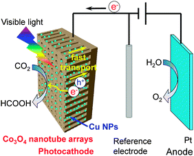 | ||
| Fig. 23 Schematic illustration of the Cu nanoparticle-decorated 1D Co3O4 nanotube array as the photocathode for the photoelectrocatalytic reduction of CO2 to formate with high efficiency.123 | ||
Only a few studies have succeeded in performing the reduction of CO2 in the photoelectrocatalytic cell without applying external bias. Very recently, Park and co-workers reported a significant progress. They found that the reduction of CO2 to formate could proceed without any external bias by using a CuFeO2 and CuO mixed p-type photocathode, which was fabricated via electroplating of cupric and ferric ions followed by annealing under atmospheric air.124 The composite electrodes exhibited onset potentials at +0.9 V vs. RHE in CO2-purged bicarbonate solution and converted CO2 to formate with >90% selectivity under simulated solar light. The CuFeO2/CuO photocathode and Pt anode couples connected by an external wire could produce formate for over 1 week at a solar-to formate energy conversion efficiency of ∼1% with O2 evolved from H2O without any external bias applied. Further elucidation of the functioning mechanism of the composite semiconductor is definitely needed in the future.
3.2 Photoanodes in combination with dark cathodes
Although many p-type semiconductor photocathodes have been reported for the reduction of CO2 in combination with an O2-evoling anode in the dark, the efficiency is still low. Over the p-type semiconductor, the 2-electron reduced products, i.e., HCOOH and CO, were usually obtained along with H2, the H2O reduction product. Moreover, the p-type semiconductor is usually expensive or unstable during the reaction. Therefore, the use of an n-type semiconductor such as TiO2, BiVO4 or WO3, which is cheap and stable, as the photoanode for H2O oxidation and an electrocatalyst that is active for CO2 reduction as the cathode to construct a type B photoelectrocatalytic cell (Fig. 21B) would also be an attractive alternative.Cheng et al. reported a combination of the Pt-modified TiO2 nanotube (Pt-TNT) photoanode and the Pt-modified reduced graphene oxide (Pt-RGO) cathode for the reduction of CO2 under UV-vis irradiation.125 Although the applied voltage was much high (+2 V), they obtained liquid products including HCOOH, CH3OH, CH3COOH and C2H5OH. The rate for the formation of these liquid products reached 0.6 μmol h−1 cm−2.125 The optimization of reaction conditions further increased the rate of product formation to 1.5 μmol h−1 cm−1.126 The exploitation of N-doped TiO2 instead of TiO2 could allow the use of visible light. The combination of the N-doped TiO2 photoanode with the Cu cathode produced CH4 and CH3OH in addition to HCOOH, although the applied bias was high (2.8 V) and the Faradaic efficiencies was low.127
Lee and co-workers recently reported an interesting work using visible-light responsive WO3 as the photoanode and Cu or Sn/SnOx, which was known to be an efficient electrocatalyst for CO2 reduction, as the cathode for CO2 reduction under visible-light irradiation.128 The system could work with a relatively lower applied bias as compared to other photoanode–cathode systems reported. When the Cu cathode was used, CH4 was mainly formed along with C2H4 and CO. The increase in the applied voltage from +0.55 V to +0.75V (vs. RHE), the Faradaic efficiencies for CH4, C2H4 and CO changed from 42.3%, 4.0% and 5.1% to 67.0%, 0.6% and 2.7%, respectively. On the other hand, when Sn/SnOx was employed as the cathode, HCOOH and CO were formed as the major reduction products besides H2. The Faradaic efficiencies for HCOOH and CO at an applied bias of 0.7 V were 27.5% and 15.8%, respectively.
3.3 Combination of photocathodes and photoanodes
It is highly desirable to perform the photoelectrocatalytic reduction of CO2 using H2O both as the electron donor and as the proton source under applied electric bias-free conditions. The use of only the photocathode or only the photoanode in combination with the counter dark anode or cathode is difficult to achieve this goal, since the valance-band edge of the photocathode and the conduction-band edge of the photoanode are typically not suited for the oxidation of H2O and the reduction of CO2, respectively. The combination of a photocathode for CO2 reduction with a photoanode for H2O oxidation is a useful strategy to realize the reduction of CO2 with H2O without external applied electric bias. For this purpose, the conduction-band edge of the photoanode for H2O oxidation must be more negative than the valance-band edge of the photocathode for CO2 reduction to guarantee the electron transfer from the photoanode to the photocathode through the external wire (Fig. 22).Sato et al. constructed a two-compartment Pyrex cell separated using a proton-exchanging membrane (Fig. 21C) using InP/[MCE2-A + MCE4] (MCE2-A = [Ru(4,4′-diphosphate ethyl-2,2′-bipyridine)(CO)2Cl2]), MCE4 = [Ru{4,4′-di(1H-pyrrolyl-3-propyl carbonate-2,2′-bipyridine}(CO)2(MeCN)Cl2)] as the photocathode and Pt/TiO2 as the photoanode (Fig. 24A).129 It should be noted that the p-type semiconductor InP alone as the photocathode was almost inactive for the reduction of CO2. The Ru complexes served as the co-catalysts for electron transfer and CO2 reduction. MCE-2A possesses an anchor ligand, i.e., 4,4′-diphosphate ethyl-2,2′-bipyridine, so that it can be linked tightly with the surface of InP. Further deeper studies indicated that MCE-2A played an important role in electron transfer, while MCE4 worked as a true active species for the reduction of CO2 to HCOO−. By using a solar simulator as the light source, the two-compartment photoelectrocatalytic cell could be run just by wiring the two photoelectrodes without external applied electrical bias. The TON for HCOOH was >17 in 24 h. Although H2 and CO were also formed, the Faradaic efficiency for HCOOH reached ∼70%. It is noteworthy that the natural photosynthesis also proceeds via the Z-scheme, which utilizes two photosystems, i.e., PS-I and PS-II. Thus, the two-compartment photocathode and photoanode system has some similarity to the natural photosynthetic system. The efficiency of the conversion of solar energy to chemical energy was estimated to be ∼0.03%, lower than the solar conversion efficiency (0.2%) for switchgrass, a crop for biofuels.
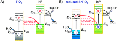 | ||
| Fig. 24 Schematic illustration of Z-scheme systems for photoelectrocatalytic reduction of CO2.129,130 (A) TiO2–InP. (B) Reduced SrTiO3–InP. | ||
A further optimization of the photoanode semiconductor could increase the efficiency for CO2 reduction. Arai et al. employed the same InP/[RuCP] (RuCP = Ru complex polymer) as the photocathode for CO2 reduction but changed the photoanode semiconductor from TiO2 to reduced SrTiO3, which had almost the same band-gap energy but more negative conduction-band and valance-band edges as compared to TiO2.130 Thus, the difference between the conduction-band edge of the photoanode and the valance-band edge of the photocathode became larger (Fig. 24B). This would facilitate the transfer of electrons from the photoanode to the photocathode, thus being beneficial to the Z-scheme reaction. The two-compartment cell using InP/[RuCP] as the photocathode and reduced SrTiO3 as the photoanode without the external electrical bias provided a stable photocurrent of 140 μA cm−2 under visible-light and UV-light irradiation on the photocathode and the photoanode, respectively. HCOOH was formed as a major product along with CO and H2. The amount of formate was 1.45 μmol after 3 h of reaction, larger than that (0.33 μmol) obtained using TiO2 as the photoanode. The Faradaic efficiency for formate formation was 71.5%. The efficiency of the conversion of solar energy to chemical energy increased to 0.14%, approaching the value for switchgrass.
Another feature of the reduced SrTiO3 is that, this semiconductor is less active for the degradation of HCOOH and other organic molecules. This feature has been harnessed by Arai et al. to construct a wireless one-compartment cell without using the proton-exchange membrane.130 HCOOH was obtained with an amount of 0.83 μmol in 3 h under irradiation on both semiconductors. Although the energy efficiency for the conversion of solar energy to chemical energy is still low (0.08%), the one-compartment cell would largely decrease the cost of the photoelectrocatalytic reactions and will open the door for developing more cheaper and efficient photoelectrocatalytic systems for the reduction of CO2 with H2O.
4. Conclusion and outlook
Significant progress has been achieved in both photocatalytic and photoelectrocatalytic reduction of CO2 with H2O based on semiconductor catalysts. Rich knowledge has been accumulated for the design and fabrication of efficient photocatalysts and photoelectrocatalysts. Generally, light harvesting, photogenerated electron–hole separation or photo-carrier transfer and surface reaction are three key steps that should be mainly considered for the design of an efficient semiconductor-based photocatalyst or photoelectrocatalyst. These are common to both H2O splitting and CO2 reduction, the two biggest challenging reactions using solar energy. The present article has highlighted some key issues that are crucial to CO2 reduction. In particular, more attention should be paid to the adsorption ability and reactivity of catalyst surfaces toward CO2 molecules. In addition to the efficiency of photogenerated electrons used for reduction, the selectivity toward CO2 reduction is a determining factor, because the reduction of H2O to H2 may occur faster on photocatalyst or photoelectrode surfaces due to the lower reactivity of CO2. The selectivity of products from CO2 reduction is another key parameter that makes the situation complicated. CO, HCOOH, CH3OH or CH4 is the typical major product depending on the catalytic system, although some C2 products such as C2H4 and CH3CH2OH have also been observed in a few systems.The structure of a semiconductor plays crucial roles in CO2 reduction through affecting either the separation of photogenerated electron–hole pairs or the reactivity of catalyst surfaces or both. For instance, the crystalline phase of TiO2 affected its photocatalytic activity for CO2 reduction not only because of the different crystalline and electronic structures but also due to the different concentration of surface defective sites (Ti3+ sites and oxygen vacancies), which may be responsible for CO2 activation. These defective sites could be easily generated on brookite TiO2 surfaces, and thus brookite after heat treatment in He showed much higher activity for CO2 reduction.37 TiO2 nanoparticles with medium particle sizes were found to be beneficial to CO2 reduction because of the balance between the number of surface sites for CO2 activation and the electronic/optical structure for light harvesting.47 The higher CO2 reduction activities of many 1D or 2D semiconductor nanowires/nanorods or nanosheets arise both from their larger concentration of surface sites and from the enhanced transfer of photogenerated electrons and holes to surfaces. The enhanced activity for a specifically exposed facet may mainly owe to the higher reactivity of the facet. The {010} facet of TiO2 was found to be active for the reduction of CO2 to CH4 because of its higher conduction-band edge position and thus the larger reduction power of the photogenerated electrons as well as higher CO2 adsorption ability, although the electron–hole separation ability of the {010} facet was rather lower than those of {001} and {101}.72,75 Furthermore, the fabrication of a semiconductor with a specific morphology and peculiar exposed facets could allow the occurrence of CO2 reduction that cannot occur on this semiconductor without such a specific morphology, because of the changed conduction-band or valance-band edge positions. WO3 is an example. The conduction-band edge position of WO3 does not allow the occurrence of the reduction of CO2 to CH4. WO3 nanosheets possess more negative conduction-band edge, and thus the reduction of CO2 becomes feasible on WO3 nanosheets.64,65 The concept of heterojunctions can also be harnessed for the design of efficient photocatalysts for CO2 reduction. The creations of phase junction and facet junction have been demonstrated to be useful strategies to facilitate the electron–hole separation.44,77,78
The noble or coinage metal or metal oxide co-catalysts can function as the active sites for CO2 reduction in addition to extracting the photogenerated electrons or holes. For the purpose of extracting electrons, Pt is the best co-catalyst. However, the selectivity for CO2 reduction would be decreased because Pt would enhance the reduction of H2O to H2 to a larger extent. Early electrocatalytic studies indicated that Ag surfaces catalysed the reduction of CO2 to CO, whereas Cu surfaces favoured the formation of hydrocarbons from CO2. Ag was actually an efficient co-catalyst for CO formation over several semiconductors.62,84 Cu2O or Cu was an efficient co-catalyst for the formation of CH4 as well as higher hydrocarbons by providing active sites for CO2 activation.89,90 Bimetallic Pt@Cu2O co-catalysts with Pt as the core and Cu2O as the shell could both efficiently extract the electrons and selectively catalyse the conversion of CO2 to CH4, showing promising performances for CH4 formation.89 Core–shell structured Ni@NiO co-catalysts had similar synergistic effects for the reduction of CO2 to CH3OH. The synergistic effect was also observed for Au–Cu and Au–Pt alloy co-catalysts, where the plasmon resonance effect of Au may contribute to the increase in the visible-light harvesting.92–94
The present article has also shown that the harnessing of a co-catalyst that can enhance the chemisorption of CO2 is an effective strategy to increase the CO2 reduction activity. Basic metal oxides, MOFs and PANI with nitrogen-containing basic functional groups are good candidates for this purpose.97–100,102–104 Significant synergistic effects have been observed between a basic metal oxide (e.g., MgO) and Pt over TiO2 for the reduction of CO2 to CH4.32,99 The chemisorbed CO2 on MgO could be reduced by the electrons trapped on the neighbouring Pt particles. A unique CO2-enhanced photosynthesis of CH4 and H2 from CO2 and H2O was observed over the Pt-doped PANI–TiO2 nanocomposites. On the PANI–TiO2 nanocomposites with or without Pt, the presence of CO2 not only caused the formation of CH4 and/or CO but also significantly enhanced the rate of H2 formation.
Photoelectrocatalysis offers further opportunities to increase the efficiency for the reduction of CO2 with H2O by combining the advantages of both photocatalysis and electrocatalysis. The separation of CO2 reduction and H2O oxidation into two compartments using two electrodes would increase the flexibility to design suitable photoelectrocatalysts or electrocatalysts for each half reaction, making the optimization of each reaction more efficiently. Studies in this field have mainly focused on the development of photocathodes based on p-type semiconductors for CO2 reduction in combination with a dark electroanode for H2O oxidation. Semiconductors such as p-GaP, p-GaAs, p-InP, p-Si, N-doped Ta2O5, Cu2O, p-NiO, p-Co3O4 and ZnTe were utilized as photocathodes along with a Pt or carbon anode. The reduction of H2O to H2 may proceed faster than the reduction of CO2 on photocathode surfaces. Co-catalysts, in particular Ru or Re complexes, which could activate CO2 and/or facilitate the transfer of electrons, showed a significant enhancing effect on the reduction of CO2. Typically, CO and HCOOH were mainly formed in these systems. Synthesis gas with different H2/CO ratios could be generated by changing the conditions on a Re-complex-modified p-Si photocathode.109 The fabrication of a 1D or 2D semiconductor photocathode could accelerate the transfer of charge carriers and thus enhance the CO2 reduction activity. For example, the 1D Co3O4 photocathode decorated with Cu nanoparticles exhibited an outstanding HCOOH formation rate.123 A couple of studies utilized n-type semiconductors as photoanodes for H2O oxidation and electrocatalysts for CO2 reduction. Not only HCOOH but also CH3OH and CH4 could be produced by choosing proper electrocatalysts. By selecting two semiconductors with proper conduction-band and valance-band edge positions as both photocathodes and photoanodes, a few studies have succeeded in the reduction of CO2 with H2O without external applied bias. For example, the use of a Ru complex polymer-modified InP and reduced SrTiO3 as the photocathode and the photoanode, respectively, HCOOH could be formed with a reasonably high efficiency, which approached that for switchgrass, an natural photosynthetic system.130
It is undoubted that many challenges remain to be solved in the future. Some of these challenges, including the increase of light harvesting efficiency and the enhancement of the separation of photogenerated electron–hole pairs, are common for photocatalysis and photoelectrocatalysis. The development of efficient visible-light responsive semiconductors with rationally designed nanostructures should be paid more attention. In more detail, the 1D or 2D morphology can accelerate the transfer of photogenerated carriers. The fabrication of semiconductors with an optimized phase junction or facet junction would largely enhance the separation of electron and hole pairs. The materials in which the photogenerated electrons and holes can move to differently exposed facets are highly attractive because of their intrinsic ability to separate electron–hole pairs and the separated regions for the reduction and oxidation reactions.
We strengthen the future need to develop efficient co-catalysts for the activation and selective reduction of CO2. Although some studies have pointed out the effects of basic metal oxides, nitrogen-containing organic polymers and Ru or Re complexes as co-catalysts, more effort should be put into the design of co-catalysts that are able to enhance the chemisorption of CO2 from the mixture of CO2 and H2O, to activate CO2 molecules preferentially and to catalyze the product formation with controllable selectivity. Many advances have been achieved in the thermal catalysis for the hydrogenation of CO2 to various products. The knowledge about the active sites and active phases in those systems can be referenced in developing more efficient co-catalysts for the photocatalytic and photoelectrocatalytic reduction of CO2 with H2O.
Acknowledgements
This work was supported by the National Basic Research Program of China (2013CB933102), the National Natural Science Foundation of China (21433008 and 21503176), the China Postdoctoral Science Foundation (No. 2015M570555) and the Program for Innovative Research Team in Chinese Universities (No. IRT_14R31).Notes and references
- (a) M. He, Y. Sun and B. Han, Angew. Chem., Int. Ed., 2013, 52, 9620–9633 CrossRef CAS PubMed; (b) G. Centi, E. A. Quadrelli and S. Perathoner, Energy Environ. Sci., 2013, 6, 1711–1731 RSC.
- W. Wang, S. Wang, X. Ma and J. Gong, Chem. Soc. Rev., 2011, 40, 3703–3727 RSC.
- T. Sakakura, J. C. Choi and H. Yasuda, Chem. Rev., 2007, 107, 2365–2387 CrossRef CAS PubMed.
- M. S. Fan, A. Z. Abdullah and S. Bhatia, ChemCatChem, 2009, 2, 192–208 CrossRef.
- A. J. Morris, G. J. Meyer and E. Fujita, Acc. Chem. Res., 2009, 42, 1983–1994 CrossRef CAS PubMed.
- T. Inoue, A. Fujishima, S. Konishi and K. Honda, Nature, 1979, 277, 637–638 CrossRef CAS.
- V. P. Indrakanti, J. D. Kubicki and H. H. Schobert, Energy Environ. Sci., 2009, 2, 745–758 CAS.
- S. C. Roy, O. K. Varghese, M. Paulose and C. A. Grimes, ACS Nano, 2010, 4, 1259–1278 CrossRef CAS PubMed.
- K. Mori, H. Yamashita and M. Anpo, RSC Adv., 2012, 2, 3165–3172 RSC.
- A. Dhakshinamoorthy, S. Navalon, A. Corma and H. Garcia, Energy Environ. Sci., 2012, 5, 9217–9233 CAS.
- (a) A. D. Handoko, K. Li and J. Tang, Curr. Opin. Chem. Eng., 2013, 2, 200–206 CrossRef; (b) K. Li, X. An, K. H. Park, M. Khraisheh and J. Tang, Catal. Today, 2014, 224, 3–12 CrossRef CAS.
- W. Fan, Q. Zhang and Y. Wang, Phys. Chem. Chem. Phys., 2013, 15, 2632–2649 RSC.
- S. N. Habisreutinger, L. Schmidt-Mende and J. K. Stolarczyk, Angew. Chem., Int. Ed., 2013, 52, 7372–7408 CrossRef CAS PubMed.
- J. Mao, K. Li and T. Peng, Catal. Sci. Technol., 2013, 3, 2481–2498 CAS.
- S. Navalón, A. Dhakshinamoorthy, M. Álvaro and H. Garcia, ChemSusChem, 2013, 6, 562–577 CrossRef PubMed.
- Y. Izumi, Coord. Chem. Rev., 2013, 257, 171–186 CrossRef CAS.
- S. Das and W. M. A. Wan Daud, RSC Adv., 2014, 4, 20856–20893 RSC.
- W. Tu, Y. Zhou and Z. Zou, Adv. Mater., 2014, 26, 4607–4626 CrossRef CAS PubMed.
- Y. Ma, X. Wang, Y. Jia, X. Chen, H. Han and C. Li, Chem. Rev., 2014, 114, 9987–10043 CrossRef CAS PubMed.
- N. Zhang, R. Ciriminna, M. Pagliaro and Y. J. Xu, Chem. Soc. Rev., 2014, 43, 5276–5287 RSC.
- D. Chen, X. Zhang and A. F. Lee, J. Mater. Chem. A, 2015, 3, 14487–14516 CAS.
- D. T. Whipple and P. J. A. Kenis, J. Phys. Chem. Lett., 2010, 1, 3451–3458 CrossRef CAS.
- K. P. Kuhl, E. R. Cave, D. N. Abram and T. F. Jaramillo, Energy Environ. Sci., 2012, 5, 7050–7059 CAS.
- H. M. Jhong, S. Ma and P. J. A. Kenis, Curr. Opin. Chem. Eng., 2013, 2, 191–199 CrossRef.
- C. Costentin, M. Robert and J. M. Savéant, Chem. Soc. Rev., 2013, 42, 2423–2436 RSC.
- J. Qiao, Y. Liu, F. Hong and J. Zhang, Chem. Soc. Rev., 2014, 43, 631–675 RSC.
- M. Halmann, Nature, 1978, 275, 115–116 CrossRef CAS.
- B. Kumar, M. Llorente, J. Froehlich, T. Dang, A. Sathrum and C. P. Kubiak, Annu. Rev. Phys. Chem., 2012, 63, 541–569 CrossRef CAS PubMed.
- J. Zhao, X. Wang, Z. Xu and J. S. C. Loo, J. Mater. Chem. A, 2014, 2, 15228–15233 CAS.
- J. Yang, D. Wang, H. Han and C. Li, Acc. Chem. Res., 2013, 46, 1900–1909 CrossRef CAS PubMed.
- A. Corma and H. Garcia, J. Catal., 2013, 308, 168–175 CrossRef CAS.
- S. Xie, Y. Wang, Q. Zhang, W. Deng and Y. Wang, ACS Catal., 2014, 4, 3644–3653 CrossRef CAS.
- A. Fujishima, X. Zhang and D. A. Tryk, Surf. Sci. Rep., 2008, 63, 515–582 CrossRef CAS.
- Q. Tay, X. Liu, Y. Tang, Z. Jiang, T. C. Sum and Z. Chen, J. Phys. Chem. C, 2013, 117, 14973–14982 CAS.
- A. Mattsson and L. Österlund, J. Phys. Chem. C, 2010, 114, 14121–14132 CAS.
- A. Kudo, K. Omori and H. Kato, J. Am. Chem. Soc., 1999, 121, 11459–11467 CrossRef CAS.
- L. Liu, H. Zhao, J. M. Andino and Y. Li, ACS Catal., 2012, 2, 1817–1828 CrossRef CAS.
- P. Li, S. Ouyang, G. Xi, T. Kako and J. Ye, J. Phys. Chem. C, 2012, 116, 7621–7628 CAS.
- P. Li, S. Ouyang, Y. Zhang, T. Kako and J. Ye, J. Mater. Chem. A, 2013, 1, 1185–1191 CAS.
- G. Li, S. Ciston, Z. V. Saponjic, L. Chen, N. M. Dimitrijevic, T. Rajh and K. A. Gray, J. Catal., 2008, 253, 105–110 CrossRef CAS.
- J. Zhang, Q. Xu, Z. Feng, M. Li and C. Li, Angew. Chem., Int. Ed., 2008, 47, 1766–1769 CrossRef CAS PubMed.
- X. Wang, Q. Xu, M. Li, S. Shen, X. Wang, Y. Wang, Z. Feng, J. Shi, H. Han and C. Li, Angew. Chem., Int. Ed., 2012, 51, 13089–13092 CrossRef CAS PubMed.
- Q. D. Truong, T. H. Le, J. Y. Liu, C. C. Chung and Y. C. Ling, Appl. Catal., A, 2012, 437–438, 28–35 CrossRef CAS.
- H. Zhao, L. Liu, J. M. Andino and Y. Li, J. Mater. Chem. A, 2013, 1, 8209–8216 CAS.
- A. J. Maira, K. L. Yeung, C. Y. Lee, P. L. Yue and C. K. Chan, J. Catal., 2000, 192, 185–196 CrossRef CAS.
- C. B. Almquist and P. Biswas, J. Catal., 2002, 212, 145–156 CrossRef CAS.
- K. Kočí, L. Obalová, L. Matějová, D. Plachá, Z. Lacný, J. Jirkovský and O. Šolcová, Appl. Catal., B, 2009, 89, 494–502 CrossRef.
- O. K. Varghese, M. Paulose, T. J. LaTempa and C. A. Grimes, Nano Lett., 2009, 9, 731–737 CrossRef CAS PubMed.
- Q. Liu, Y. Zhou, J. Kou, X. Chen, Z. Tian, J. Gao, S. Yan and Z. Zou, J. Am. Chem. Soc., 2010, 132, 14385–14387 CrossRef CAS PubMed.
- S. Yan, L. Wan, Z. Li and Z. Zou, Chem. Commun., 2011, 47, 5632–5634 RSC.
- Q. Liu, Y. Zhou, Z. Tian, X. Chen, J. Gao and Z. Zou, J. Mater. Chem., 2012, 22, 2033–2038 RSC.
- Q. Liu, Y. Zhou, W. Tu, S. Yan and Z. Zou, Inorg. Chem., 2014, 53, 359–364 CrossRef CAS PubMed.
- Q. Liu, Y. Zhou, Y. Ma and Z. Zou, RSC Adv., 2012, 2, 3247–3250 RSC.
- S. Feng, X. Chen, Y. Zhou, W. Tu, P. Li, H. Li and Z. Zou, Nanoscale, 2014, 6, 1896–1900 RSC.
- P. Li, Y. Zhou, W. Tu, Q. Liu, S. Yan and Z. Zou, ChemPlusChem, 2013, 78, 274–278 CrossRef CAS.
- G. Xi, S. Ouyang, P. Li, J. Ye, Q. Ma, N. Su, H. Bai and C. Wang, Angew. Chem., Int. Ed., 2012, 51, 2395–2399 CrossRef CAS PubMed.
- W. Tu, Y. Zhou, Q. Liu, Z. Tian, J. Gao, X. Chen, H. Zhang, J. Liu and Z. Zou, Adv. Funct. Mater., 2012, 22, 1215–1221 CrossRef CAS.
- Y. T. Liang, B. K. Vijayan, O. Lyandres, K. A. Gray and M. C. Hersam, J. Phys. Chem. Lett., 2012, 3, 1760–1765 CrossRef CAS PubMed.
- Q. Liu, D. Wu, Y. Zhou, H. Su, R. Wang, C. Zhang, S. Yan, M. Xiao and Z. Zou, ACS Appl. Mater. Interfaces, 2014, 6, 2356–2361 CAS.
- Z. Li, Y. Zhou, J. Zhang, W. Tu, Q. Liu, T. Yu and Z. Zou, Cryst. Growth Des., 2012, 12, 1476–1481 CAS.
- X. Li, H. Pan, W. Li and Z. Zhuang, Appl. Catal., A, 2012, 413–414, 103–108 CAS.
- K. Li, A. D. Handoko, M. Khraisheh and J. Tang, Nanoscale, 2014, 6, 9767–9773 RSC.
- S. Xie, Y. Wang, Q. Zhang, W. Deng and Y. Wang, Chem. Commun., 2015, 51, 3430–3433 RSC.
- X. Chen, Y. Zhou, Q. Liu, Z. Li, J. Liu and Z. Zou, ACS Appl. Mater. Interfaces, 2012, 4, 3372–3377 CAS.
- Y. Xie, G. Liu, L. Yin and H. Cheng, J. Mater. Chem., 2012, 22, 6746–6751 RSC.
- Y. Zhou, Z. Tian, Z. Zhao, Q. Liu, J. Kou, X. Chen, J. Gao, S. Yan and Z. Zou, ACS Appl. Mater. Interfaces, 2011, 3, 3594–3601 CAS.
- C. Burda, X. Chen, R. Narayanan and M. A. El-Sayed, Chem. Rev., 2005, 105, 1025–1102 CrossRef CAS PubMed.
- Y. Li and W. Shen, Chem. Soc. Rev., 2014, 43, 1543–1574 RSC.
- H. G. Yang, C. H. Sun, S. Z. Qiao, J. Zou, G. Liu, S. C. Smith, H. M. Cheng and G. Q. Lu, Nature, 2008, 453, 638–641 CrossRef CAS PubMed.
- H. Yang, G. Liu, S. Qiao, C. Sun, Y. Jin, S. Smith, J. Zou, H. Cheng and G. Lu, J. Am. Chem. Soc., 2009, 131, 4078–4083 CrossRef CAS PubMed.
- X. Han, Q. Kuang, M. Jin, Z. Xie and L. Zheng, J. Am. Chem. Soc., 2009, 131, 3152–3153 CrossRef CAS PubMed.
- J. Pan, X. Wu, L. Wang, G. Liu, G. Lu and H. Cheng, Chem. Commun., 2011, 47, 8361–8363 RSC.
- W. Jiao, L. Wang, G. Liu, G. Lu and H. Cheng, ACS Catal., 2012, 2, 1854–1859 CrossRef CAS.
- H. Xu, S. Ouyang, P. Li, T. Kako and J. Ye, ACS Appl. Mater. Interfaces, 2013, 5, 1348–1354 CAS.
- L. Ye, J. Mao, T. Peng, L. Zan and Y. Zhang, Phys. Chem. Chem. Phys., 2014, 16, 15675–15680 RSC.
- Z. He, L. Wen, D. Wang, Y. Xue, Q. Lu, C. Wu, J. Chen and S. Song, Energy Fuels, 2014, 28, 3982–3993 CrossRef CAS.
- J. Yu, J. Low, W. Xiao, P. Zhou and M. Jaroniec, J. Am. Chem. Soc., 2014, 136, 8839–8842 CrossRef CAS PubMed.
- P. Li, Y. Zhou, Z. Zhao, Q. Xu, X. Wang, M. Xiao and Z. Zou, J. Am. Chem. Soc., 2015, 137, 9547–9550 CrossRef CAS PubMed.
- C. Wang, R. L. Thompson, P. Ohodnicki, J. Baltrus and C. Matranga, J. Mater. Chem., 2011, 21, 13452–13457 RSC.
- H. Shi, G. Chen, C. Zhang and Z. Zou, ACS Catal., 2014, 4, 3637–3643 CrossRef CAS.
- G. Xi, S. Ouyang and J. Ye, Chem. – Eur. J., 2011, 17, 9057–9061 CrossRef CAS PubMed.
- S. I. In, D. D. Vaughn and R. E. Schaak, Angew. Chem., Int. Ed., 2012, 51, 3915–3918 CrossRef CAS PubMed.
- Y. He, L. Zhang, B. Teng and M. Fan, Environ. Sci. Technol., 2015, 49, 649–656 CrossRef CAS PubMed.
- K. Iizuka, T. Wato, Y. Miseki, K. Saito and A. Kudo, J. Am. Chem. Soc., 2011, 133, 20863–20868 CrossRef CAS PubMed.
- Y. Hori, H. Wakebe, T. Tsukamoto and O. Koga, Electrochim. Acta, 1994, 39, 1833–1839 CrossRef CAS.
- A. A. Peterson and J. K. Nørskov, J. Phys. Chem. Lett., 2012, 3, 251–258 CrossRef CAS.
- W. Wang, W. An, B. Ramalingam, S. Mukherjee, D. Niedzwiedzki, S. Gangopadhyay and P. Biswas, J. Am. Chem. Soc., 2012, 134, 11276–11281 CrossRef CAS PubMed.
- X. Zhang, F. Han, B. Shi, S. Farsinezhad, G. P. Dechaine and K. Shankar, Angew. Chem., Int. Ed., 2012, 51, 12732–12735 CrossRef CAS PubMed.
- Q. Zhai, S. Xie, W. Fan, Q. Zhang, Y. Wang, W. Deng and Y. Wang, Angew. Chem., Int. Ed., 2013, 52, 5776–5779 CrossRef CAS PubMed.
- S. Zhu, S. Liang, Y. Tong, X. An, J. Long, X. Fu and X. Wang, Phys. Chem. Chem. Phys., 2015, 17, 9761–9770 RSC.
- C. Tsai, H. Chen, R. Liu, K. Asakura and T. Chan, J. Phys. Chem. C, 2011, 115, 10180–10186 CAS.
- S. Neatu, J. A. Maciá-Agulló, P. Concepción and H. Garcia, J. Am. Chem. Soc., 2014, 136, 15969–15976 CrossRef CAS PubMed.
- Q. Kang, T. Wang, P. Li, L. Liu, K. Chang, M. Li and J. Ye, Angew. Chem., Int. Ed., 2015, 54, 841–845 CrossRef CAS PubMed.
- Z. Zhang, Z. Wang, S. Cao and C. Xue, J. Phys. Chem. C, 2013, 117, 25939–25947 CAS.
- B. D. Mankidy, B. Joseph and V. K. Gupta, Nanotechnology, 2013, 24, 405402 CrossRef PubMed.
- J. Yang, D. Wang, H. Han and C. Li, Acc. Chem. Res., 2013, 46, 1900–1909 CrossRef CAS PubMed.
- L. Liu, C. Zhao, H. Zhao, D. Pitts and Y. Li, Chem. Commun., 2013, 49, 3664–3666 RSC.
- L. Liu, C. Zhao, D. Pitts and Y. Li, Catal. Sci. Technol., 2014, 4, 1539–1546 CAS.
- S. Xie, Y. Wang, Q. Zhang, W. Fan, W. Deng and Y. Wang, Chem. Commun., 2013, 49, 2451–2453 RSC.
- X. Meng, S. Ouyang, T. Kako, P. Li, Q. Liu, T. Wang and J. Ye, Chem. Commun., 2014, 50, 11517–11519 RSC.
- Y. Fu, D. Sun, Y. Chen, R. Huang, Z. Ding, X. Fu and Z. Li, Angew. Chem., Int. Ed., 2012, 51, 3364–3367 CrossRef CAS PubMed.
- Q. Liu, Z. X. Low, L. Li, A. Razmjou, K. Wang, J. Yao and H. Wang, J. Mater. Chem. A, 2013, 1, 11563–11569 CAS.
- Y. Liao, S. W. Cao, Y. Yuan, Q. Gu, Z. Zhang and C. Xue, Chem. – Eur. J., 2014, 20, 10220–10222 CrossRef CAS PubMed.
- G. Liu, S. Xie, Q. Zhang, Z. Tian and Y. Wang, Chem. Commun., 2015, 51, 13654–13657 RSC.
- A. G. MacDiarmid and A. J. Epstein, Faraday Discuss. Chem. Soc., 1989, 88, 317–332 RSC.
- S. Sato, T. Morikawa, S. Saeki, T. Kajino and T. Motohiro, Angew. Chem., Int. Ed., 2010, 49, 5101–5105 CrossRef CAS PubMed.
- T. Arai, S. Sato, K. Uemura, T. Morikawa, T. Kajino and T. Motohiro, Chem. Commun., 2010, 46, 6944–6946 RSC.
- T. Arai, S. Tajima, S. Sato, K. Uemura, T. Morikawa and T. Kajino, Chem. Commun., 2011, 47, 12664–12666 RSC.
- B. Kumar, J. M. Smieja, A. F. Sasayama and C. P. Kubiak, Chem. Commun., 2012, 48, 272–274 RSC.
- M. Schreier, P. Gao, M. T. Mayer, J. Luo, T. Moehl, M. K. Nazeeruddin, S. D. Tilley and M. Grätzel, Energy Environ. Sci., 2015, 8, 855–861 CAS.
- A. Paracchino, V. Laporte, K. Sivula, M. M. Grätzel and E. Thimsen, Nat. Mater., 2011, 10, 456–461 CrossRef CAS PubMed.
- Y. Kou, S. Nakatani, G. Sunagawa, Y. Tachikawa, D. Masui, T. Shimada, S. Takagi, D. A. Tryk, Y. Nabetani, H. Tachibana and H. Inoue, J. Catal., 2014, 310, 57–66 CrossRef CAS.
- G. Sahara, R. Abe, M. Higashi, T. Morikawa, K. Maeda, Y. Ueda and O. Ishitani, Chem. Commun., 2015, 51, 10722–10725 RSC.
- D. H. Won, J. Chung, S. H. Park, E. H. Kim and S. I. Woo, J. Mater. Chem. A, 2015, 3, 1089–1095 CAS.
- Y. Xia, P. Yang, Y. Sun, Y. Wu, B. Mayers, B. Gates, Y. Yin, F. Kim and H. Yan, Adv. Mater., 2003, 15, 353–389 CrossRef CAS.
- Y. Lin, G. Yuan, R. Liu, S. Zhou, S. W. Sheehan and D. Wang, Chem. Phys. Lett., 2011, 507, 209–215 CrossRef CAS.
- J. Jang, S. Cho, G. Magesh, Y. Jang, J. Kim, W. Kim, J. Seo, S. Kim, K. Lee and J. Lee, Angew. Chem., Int. Ed., 2014, 53, 5852–5857 CrossRef CAS PubMed.
- G. Ghadimkhani, N. R. de Tacconi, W. Chanmanee, C. Janaky and K. Rajeshwar, Chem. Commun., 2013, 49, 1297–1299 RSC.
- A. T. Garcia-Esparza, K. Limkrailassiri, F. Leroy, S. Rasul, W. Yu, L. Lin and K. Takanabe, J. Mater. Chem. A, 2014, 2, 7389–7401 CAS.
- D. Won, C. Choi, J. Chung and S. Woo, Appl. Catal., B, 2014, 158–159, 217–223 CrossRef CAS.
- J. Brito, A. Araujo, K. Rajeshwa and M. Zanoni, Chem. Eng. J., 2015, 264, 302–309 CrossRef.
- X. Huang, T. Cao, M. Liu and G. Zhao, J. Phys. Chem. C, 2013, 117, 26432–26440 CAS.
- Q. Shen, Z. Chen, X. Huang, M. Liu and G. Zhao, Environ. Sci. Technol., 2015, 49, 5828–5835 CrossRef CAS PubMed.
- U. Kang, S. K. Choi, D. J. Ham, S. M. Ji, W. Choi, D. S. Han, A. Abdel-Wahab and H. Park, Energy Environ. Sci., 2015, 8, 2638–2643 CAS.
- J. Cheng, M. Zhang, G. Wu, X. Wang, J. Zhu and K. Cen, Environ. Sci. Technol., 2014, 48, 7076–7084 CrossRef CAS PubMed.
- J. Cheng, M. Zhang, G. Wu, X. Wang, J. Zhou and K. Cen, Sol. Energy Mater. Sol. Cells, 2015, 132, 606–614 CrossRef CAS.
- Y. P. Peng, Y. T. Yeh, S. I. Shah and C. P. Huang, Appl. Catal., B, 2012, 123–124, 414–423 CrossRef CAS.
- G. Magesh, E. S. Kim, H. J. Kang, M. Banu, J. Y. Kim, J. H. Kim and J. S. Lee, J. Mater. Chem. A, 2014, 2, 2044–2049 CAS.
- S. Sato, T. Arai, T. Morokawa, K. Uemura, T. M. Suzuki, H. Tanaka and T. Kajino, J. Am. Chem. Soc., 2011, 133, 15240–15243 CrossRef CAS PubMed.
- T. Arai, S. Sato, T. Kajino and T. Morikawa, Energy Environ. Sci., 2013, 6, 1274–1282 CAS.
| This journal is © The Royal Society of Chemistry 2016 |


