 Open Access Article
Creative Commons Attribution 3.0 Unported Licence
Automated analysis of single cells using Laser Tweezers Raman Spectroscopy
S.
Casabella
ab,
P.
Scully
b,
N.
Goddard
a and
P.
Gardner
*a
aManchester Institute of Biotechnology, The University of Manchester, 131 Princess Street, M1 7DN, UK. E-mail: peter.gardner@manchester.ac.uk
bThe Photon Science Institute, The University of Manchester, Oxford Road, Manchester, M13 9PL, UK
First published on 10th November 2015
Abstract
In recent years, significant progress has been made into the label-free detection and discrimination of individual cancer cells using Laser Tweezers Raman Spectroscopy (LTRS). However, the majority of examples reported have involved manual trapping of cells, which is time consuming and may lead to different cell lines being analysed in discrete batches. A simple, low-cost microfluidic flow chamber is introduced which allows single cells to be optically trapped and analysed in an automated fashion, greatly reducing the level of operator input required. Two implementations of the flow chamber are discussed here; a basic single-channel device in which the fluid velocity is controlled manually, and a dual-channel device which permits the automated capture and analysis of multiple cell lines with no operator input. Results are presented for the discrimination of live epithelial prostate cells and lymphocytes, together with a consideration of the consequences of traditional ‘batch analysis’ typically used for LTRS of live cells.
1. Introduction
One in two people born after 1960 in the United Kingdom will be diagnosed with some form of cancer during their lifetime. Analysis of cancer at the bulk level means that individual attributes may be averaged, and single cell detection and interrogation techniques are therefore of particular interest. In recent years, Laser Tweezers Raman Spectroscopy (LTRS) has been shown to be a powerful tool for the label-free analysis of individual cancer cells. LTRS is particularly suited to the study of live cells, since this technique allows cells to be trapped and analysed in an aqueous environment, free of any morphological changes associated with culturing cells onto a substrate.To date, LTRS has been shown to be a viable method of distinguishing between a number of epithelial prostate cell lines and primary bladder cells, including cells exposed to synthetic urine, which confirms the potential for a method of urine cytology based on vibrational spectroscopy.1,2 In addition to the classification of epithelial cell lines, LTRS has more recently been used to differentiate between epithelial cancer cells and leukocytes.3 As with urine cytology, such studies have a direct clinical application, since the detection of Circulating Tumor Cells in peripheral blood may provide information relating to the primary tumour and the impact of any treatment.
For the majority of examples of LTRS completed, the initial capture of cells has required a high degree of operator input, with cells often manually trapped with the use of a translation stage coupled to a microscope. In addition to the requirement for an individual to be present, manual trapping of cells in static dishes naturally leads to different cell lines being analysed in discrete batches, possibly under different conditions. This is a particular issue for live cell analysis as removing cells from culture medium will instigate a number of biochemical events. In this paper we describe the development of an automated system for which no operator input is required, which allows two different cell lines to be captured at shorter intervals, minimizing the impact of batch analysis of live cells.
2. Experimental
2.1. LTRS arrangement
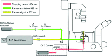
The LTRS arrangement used for single cell analysis is shown in Fig. 1. The system employs two separate wavelengths (1064 nm and 532 nm), for optical trapping and Raman excitation respectively. The two diode pumped solid state (DPSS) lasers (Laser Quantum, UK) are introduced to the side and rear ports of an inverted microscope (Nikon Eclipse TE300) and focussed using a 1.30 NA oil immersion lens. Backscattered Raman light is collected using an f/4.1 spectrometer (iHR-320, Horiba Scientific, UK), equipped with a CCD (1024 × 256 pixels), thermoelectrically cooled to −60 °C. The microfluidic chambers described in section 2.2 are positioned on a translation stage (Prior Scientific, UK), allowing the devices to be manipulated relative to the fixed focal position of the 1064 nm and 532 nm beams.2.2. Flow chamber fabrication
The flow chambers used for cell capture and Raman analysis have been fabricated via laser ablation of a membrane switch spacer (3M 7961MP, Cadillac Plastics Ltd). The switch spacer is comprised of a 178 μm polyester layer coated on each side with a 50 μm acrylic adhesive, resulting in a total channel height of 278 μm. A commercial CO2 laser cutter (LS3040, HPC Laser Ltd) is used to remove a channel from the spacer, with typical channel widths of the order of 500 μm. Once the channel has been cut, the protective paper is removed from both sides of the spacer, with one side sealed to a glass coverslip and the opposing side to a PMMA layer, also cut using the CO2 laser. Entrance and exit ports are completed by sealing 1.35 mm diameter uninsulated bootlace ferrules to the holes in the upper substrate using epoxy adhesive (Fig. 2). The exit port is connected to a 1 mL syringe using PVC tubing (Portex 800/000/180). The entrance port is formed by attaching a 500 μL pipette tip to the second port, allowing cells to be added at regular intervals. Operating with an open port in this manner allows live cells to be kept refrigerated until required and reduces the impact of cell sedimentation. Control of the volumetric flow rate within the devices was achieved using a syringe pump (Fusion 200, Chemyx). Both Raman and trapping lasers, translation stage and syringe pump are controlled using a single LabVIEW virtual instrument (VI) which has been based on a VI supplied by Horiba Scientific for the acquisition of spectra using the iHR-320.2.3. Cell culture
The PC-3 prostate cell line (ATCC CRL-1435) was established in 1979 from a bone metastasis in a 62 year old male. The cell line is androgen insensitive, poorly differentiated, adherent, and exhibits high tumorigenicity. The Jurkat cell line (ATCC TIB-152) was established from the peripheral blood of a 14 year old male. The cell line is a T lymphocyte with lymphoblast morphology. PC-3 and Jurkat cells were cultured in RPMI growth medium (R0883, Sigma Aldrich) supplemented with 10% fetal calf serum and 1% L-glutamine and penicillin streptomycin. Cells were maintained in T25 culture flasks at 37 °C and 5% CO2. PC-3 cells were harvested using trypsin – EDTA (T3924, Sigma Aldrich). Prior to analysis, all cell were centrifuged twice, suspended in PBS and refrigerated at 4 °C.2.4. Basic device operation and data extraction
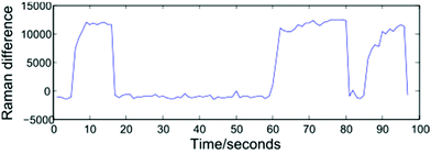
Modelling a cell as a perfect sphere with radius r, for a cell travelling with velocity V past the focal point of the 1064 nm and 532 nm beams to become trapped requires the gradient force, Fgrad to exceed the Stokes force imparted by the surrounding fluid, FS = 6πηrVβ. Trapping and release of cells may be implemented using one of two approaches: selecting a constant fluid velocity at which Fgrad > FS, or alternating between high (Fgrad ≪ FS) and low (Fgrad > FS) fluid velocities. In the first case, a trapped cell will be displaced from the equilibrium position and can be removed from the optical trap by blocking both beams. The second approach, which has been adopted for the work described here, alternates between flow rates of zero (allowing cells to be trapped at the equilibrium position), and 5000 μL h−1. This higher flow rate both removes cells from the optical trap once a Raman spectrum has been acquired and assists in preventing cells from settling on the glass coverslip surface. The frequency at which the flow rate is varied may be controlled manually by an operator, or set to alternate at fixed intervals, and both approaches are presented below.In order to monitor the frequency at which cells enter and exit the trap, the spectrometer is set to continuously acquire spectra at 1 second intervals. Operating the system in this way removes a disadvantage associated with manual trapping, which requires the user to locate a cell using white light illumination which is then turned off before a Raman spectrum is acquired, with an associated delay. Having acquired a number of sequential spectra, extraction of an individual cell spectrum simply requires a threshold to be selected, and numerically sequential spectra exceeding the threshold to be grouped together. Shown in Fig. 3 is a plot of the difference in Raman intensity at 2945 and 2995 cm−1, recorded over a period of 100 seconds. The plot shows three separate cells being optically trapped at t = 5, 60 and 85 seconds, with the cells retained until such time as the flow rate is increased.
A variety of thresholding options exist, including the intensity of a single Raman peak, the combined intensity over a range of wavenumbers, or the ratio/difference in the intensity of two peaks. For the data presented in section 3.1, a 1800 lines per mm diffraction grating covering the range 690–1750 cm−1 has been used. In such cases, the total Raman intensity was found to be the most reliable method of distinguishing between cell and background spectra, however the resultant thresholding plots contain a high amount of noise. For the fully automated device discussed in section 4, the use of a 600 lines per mm grating allows both the fingerprint and high wavenumber regions to be recorded for a static grating position. The increased signal-to-noise ratio and reduced background in the high wavenumber region make the height of the CH2/CH3 str band a more reliable thresholding method as shown in Fig. 3, in which the difference in intensity at 2945 and 2995 cm−1 represents the height of this band.
Following thresholding, spectra corresponding to separate cells may be immediately combined, or may be truncated such that the total acquisition time for all cells is equivalent. For the data presented here, cell spectra have been truncated by retaining only the first 10 or 5 individual 1 second spectra. Since the flow chamber operates with a static beam position, a single background spectrum acquired at the start of each experiment is subtracted from each average cell spectrum. All stages of the data extraction process are completed using a single MATLAB program.
3. Results
3.1. Discrimination of PC-3 and Jurkat cells
Circulating Tumour Cells (CTCs) are cells which are shed into the blood system from a primary tumour. In the case of prostate cancer, prognosis is strongly dependent on whether cancer has spread to secondary sites, with outlook particularly poor for individuals with secondary bone metastases.4,5 Current methods of diagnosis for prostate cancer include Prostate Specific Antigen (PSA) testing followed by histological (Gleason grading) of tissue samples. The former technique suffers from a high rate of false positives while the latter has proved to be a subjective process, as confirmed by a 2002 study in which different pathologists selected identical Gleason grades in only 30% of cases.6 As an alternative to these diagnostic methods, a number of groups have proposed the use of Raman and FTIR spectroscopy, both for the analysis of single cells and as a method of classifying frozen and fixed prostate cores.7–11 It has been suggested that, for late stage (androgen independent) prostate cancer, detecting the number of CTCs in a sample of peripheral blood may also have some diagnostic potential, both in terms of establishing the current staging of the disease and in assessing the effectiveness of treatment.12At present, isolation of CTCs from a blood sample can be achieved with the use of cell surface markers such the epithelial cell-adhesion molecule (EpCAM), a membrane glycoprotein which is expressed on epithelial cells but not on leukocytes. Such methods employ external chemical labels, and may also require cells to be fixed prior to staining. A method of differentiating between CTCs and white blood cells using vibrational spectroscopy would therefore complement the existing diagnostic techniques described above.
To verify the potential for LTRS to be used to differentiate between CTCs and white blood cells, the metastatic PC-3 prostate cell line and Jurkat cells have been selected. In order to reduce the impact of differences in cell preparation, a total of 6 T25 culture flasks were selected for Raman analysis (3 flasks of adherent PC-3 cells and 3 flasks of Jurkat suspension cells). Cells were harvested as described above in pairs and analysed using the single channel device shown in Fig. 2a. Using multiple culture flasks in this way allows classification rates to be assessed based on completely independent sets of data analysed in three batches on the same day. For each cell type, cells were added to the open port of the device, and the flow rate was manually varied between zero and 5000 μL h−1 using the LabVIEW VI. Every 10–15 minutes, the channel was flushed with PBS and the cell line under analysis was switched. Continuously switching between cells lines in this manner reduces the impact of changes to the condition of live cells during the course of a single experiment (typically 2–3 hours for each pair of flasks).
3.2. PC-3 and Jurkat cell spectra
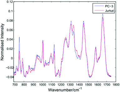
After thresholding the data and retaining cell spectra of duration 5 seconds for each trapped cell, a total of 296 spectra were retained for analysis as shown in Table 1. Following the removal of a 5 second background from each spectrum, a 4th order polynomial baseline has been fitted and subtracted. Shown in Fig. 4 are the mean spectra for all 153 PC-3 and 143 Jurkat cells.| Flask | Cells | Set 1 | Set 2 | Set 3 |
|---|---|---|---|---|
| 1 | 47 Jurkat | Train 1 | Test 2 | Test 3 |
| 2 | 47 PC-3 | |||
| 3 | 38 Jurkat | Test 1 | Train 2 | Test 3 |
| 4 | 45 PC-3 | |||
| 5 | 58 Jurkat | Test 1 | Test 2 | Train 3 |
| 6 | 61 PC-3 |
The average PC-3 spectrum displays increased intensities at 745, 1127 and 1314 cm−1 due to cytochrome-c, a heme protein involved in cellular respiration which undergoes resonance Raman scattering at 532 nm excitation.13,14 The 745 cm−1 band, due to the pyrrole breathing mode (ν15) of the protein is particularly enhanced in these cells. In addition to cytochrome-c, PC-3 cells display enhanced bands at 1451 cm−1 (C–H def, proteins/lipids) and 1659 cm−1 (amide I). For the average Jurkat spectrum, enhanced bands are indicative of nucleic acids, at 783 cm−1 (DNA phosphodiester), 1095 cm−1 (DNA phosphodioxy), 1340 cm−1 (A,G), together with a shoulder at 1378 cm−1 (T,A,G). However, the increase in nucleic acids compared to lipids/proteins in the Jurkat cells may in part be due to cell size, since lymphocytes have a high nucleus to cytoplasm ratio. In a LTRS comparison of leukocytes taken from volunteers and three cultured cell lines, Dochow et al. observed enhanced bands at 1580, 1557, and 1373 cm−1 in the leukocytes.15 Although no difference in the second of these bands is observed here, the 1378 cm−1 band is increased in the Jurkat cells, and it is possible that any increase in the 1580 cm−1 band has been compensated for by the 1579 cm−1 cytochrome-c band in the PC-3 cells.
Fig. 5 shows a Principal Component Analysis (PCA) plot for the 296 cells, together with a loadings plot for the first component.
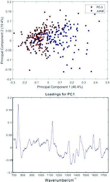 | ||
| Fig. 5 Principal Component Analysis (PCA) plot for the PC-3 and Jurkat cells, together with a loadings plot for the first component. | ||
The PCA scores plot shows a partial separation of the two cell lines along the first principal component, with PC-3 cells generally displaying positive scores. As with the average spectra shown in Fig. 4, the loading for this component confirms enhanced bands due to cytochrome-c (745, 1127, 1314, 1579 cm−1) in the PC-3 cells, with the Jurkat cells displaying increased nucleic acid bands, at 783 cm−1 (phosphodiester), 1095 cm−1 (phosphodioxy), 1340 cm−1 (A,G) and 1378 cm−1 (T,A,G).
3.3. LDA classification: all spectral regions
Linear Discriminant Analysis (LDA) has been carried out on the 296 cell spectra (15 principal components retained). Shown below in Table 2 are the classification results for the three independent data sets shown in Table 1. Since the data extraction method outlined in section 2.4 involves individual 1 second spectra being combined to produce cell averages, classification rates based on both 5 and 2 second acquisition times may be calculated by retaining only the corresponding number of spectra for the 296 cells.| Flask | Cells | LDA classification rate (5 seconds) | LDA classification rate (2 seconds) |
|---|---|---|---|
| 3,4,5,6 | 96 Jurkat | 192/202 (95.0%) | 184/202 (91.1%) |
| 106 PC-3 | |||
| 1,2,5,6 | 105 Jurkat | 210/213 (98.6%) | 187/213 (87.8%) |
| 108 PC-3 | |||
| 1,2,3,4 | 85 Jurkat | 172/177 (97.1%) | 169/177 (95.5%) |
| 92 PC-3 |
3.4. LDA classification: 1314/1340 cm−1 ratio
The average spectra shown in Fig. 4 confirm an increase in the ratio of the closely spaced 1314/1340 cm−1 bands (cytochrome-c and nucleic acids (A,G)) in the PC-3 cells. Using only the ratio of these two peak intensities to construct an LDA model, classification rates for the three test sets at a 5 second integration time are 85%, 87% and 81% respectively. At 2 seconds integration time, the equivalent rates are 81%, 82% and 83%.The classification rates using PCA–LDA and those based on the ratio of the 1314/1340 cm−1 bands confirm that individual cell spectra of sufficient quality may be extracted using the dual flow method presented in section 2.4. The rates shown in Table 2 compare well with studies completed by Dochow et al., in which a fibre-based optical trap was used to differentiate between fixed leukocytes and a number of cultured epithelial cell lines.16
4. Dual channel device
The PC-3 and Jurkat cell data presented in sections 3.1–3.4 has been obtained using a single channel flow chamber with pump speed controlled in real time by an operator. While this arrangement represents an improvement over manual trapping, the requirement to flush the single channel with PBS as cell lines are alternately analysed is time consuming, and may again lead to an element of batch analysis, unless flushing of the channel takes place at sufficiently short intervals. Shown in Fig. 2b is a modified device comprised of two separate, parallel channels. By moving the position of the device relative to the trapping/Raman beams using the translation stage, cells contained in the two channels may be alternately trapped, removing the requirement to flush a single channel.In addition to the analysis of two different cell lines, the dual channel device may be used to investigate the influence of different conditions on a single cell line, including drug-cell interaction studies. While the device shown in Fig. 2b contains two channels, the automated acquisition method outlined below in section 4.1 may be used with any number of channels, allowing time-dependant changes for a single live cell line exposed to a drug to be investigated.
In the following sections, the dual channel device has been used to investigate the impact of: (a) changes in the condition of live cells with time, (b) changes in experimental conditions between batches.
4.1. Changes in live cells stored in PBS
For any live cell analysis such as the PC-3/Jurkat data presented above, removing cells from controlled growth conditions will have an impact on cell biochemistry, and it is important to confirm whether such changes are reflected in the Raman cell spectra obtained.Using a single T75 flask of Jurkat cells, half of the total contents (10 mL) were removed and prepared via centrifuging and resuspending in PBS as described in section 2.3. These cells were then stored at 4 °C for a period of 3.5 hours, at which time the remaining contents of the same flask was prepared using the same protocol and suspended in PBS, again at 4 °C. Using a suspension cell line such as Jurkat cells in this manner allows a mixed population of cells to be withdrawn from a flask without influencing the remaining cells. Prior to Raman analysis, a trypan blue exclusion test was used to estimate viability for the refrigerated cells and those prepared immediately prior to the experiment. The two channel device with fully automated acquisition was then used, with the two cell populations added to separate ports. The flow rate of the syringe pump was varied between 5000 μL h−1 and zero (cycles of 5 and 15 seconds respectively). Automatic switching between the two channels occurred at the maximum stage velocity (60 mm s−1) every 120 seconds. The frequency of both processes is pre-set using the LabVIEW acquisition program, and the only operator input required for the duration of the experiment was the addition of cells to the two open ports of the device.
Table 3 shows a summary of the number of cells captured during a 50 minute period, together with estimated cell viability numbers, based on the trypan blue test.
| Channel 1 | Channel 2 | |
|---|---|---|
| Cell line | Jurkat (t = 3.5 hours) | Jurkat (t = 0 hours) |
| Percentage of live cells | 68% | 92% |
| Number of cells trapped >10 seconds | 74 | 69 |
Following thresholding, any cells captured for less than 10 seconds were excluded, and the remaining cell spectra were truncated to 10 seconds each. Fig. 6 shows average spectra, PCA scores and first loading plots for the 143 cells, with cells removed from the growth medium immediately before and 3.5 hours prior to the experiment shown in blue and red respectively.
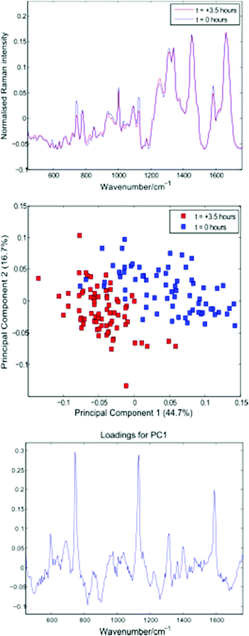 | ||
| Fig. 6 Average cell spectra, PCA plot and first loading for the 143 cells summarised in Table 3. | ||
Both the average spectra and PCA plot confirm a reduction in cytochrome-c levels in the Jurkat cells stored in PBS for 3.5 hours. The distribution and total concentration of cytochrome-c is known to alter in response to apoptosis, with levels shown to increase first in the cytoplasm and later in the nucleus of HeLa cells via immunouorescence and subcellular fractionation.17 It is possible that the reduction in cytochrome-c demonstrated above is the result of a change in cytochrome-c levels within the localised region of the trapped cells probed by the Raman beam.
4.2. Influence of changes in experimental conditions
In addition to changes in cell biochemistry, a further consequence of conventional Raman analysis of single cells being conducted in discrete batches is the possibility of changes in experimental conditions, such as a drift in laser wavelength or spectrometer temperature. As noted by Fukura et al.,18 changes in spectrometer temperature will result in the Raman spectrum migrating across the plane of the CCD as the optics of the spectrometer adjust. Such a shift in the position of a spectrum can be simulated by adjusting the intensity value in each CCD pixel by a fixed percentage of the neighbouring pixel. Fig. 7 shows a difference spectrum for two Raman spectra (PC-3 cells, 30 seconds acquisition time, shown in blue). After applying an effective shift of half of one pixel to one of the original spectra, a second difference spectrum can be calculated (shown in red).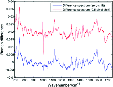 | ||
| Fig. 7 Difference spectrum for two single PC-3 cells before (blue) and after (red) the application of a lateral shift of 0.5 pixels. | ||
The lateral shift of one of the original spectra is evident in the second difference spectrum only at the position of the sharp phenylalanine peak at 1001 cm−1. Since sharper peaks are the result of a large difference in the number of photons striking adjacent CCD pixels, the effect of a temperature induced shift of one spectrum will be more pronounced in such regions. The presence of an anti-correlated feature at the 1001 cm−1 phenylalanine band in difference spectra or PCA loadings has been reported by a number of authors using LTRS or conventional Raman spectroscopy, and has been attributed to a number of causes, such as differences in the hydrogen bonding of the C![[double bond, length as m-dash]](https://www.rsc.org/images/entities/char_e001.gif) O bond and a difference in protein composition, both across cell types and as a result of formalin fixation.1,19,20 However, given the extended timescales required for typical single-cell Raman experiments, it is important to also consider the role of temperature induced changes as batches of spectra are acquired.
O bond and a difference in protein composition, both across cell types and as a result of formalin fixation.1,19,20 However, given the extended timescales required for typical single-cell Raman experiments, it is important to also consider the role of temperature induced changes as batches of spectra are acquired.
In order to verify the likelihood of a shift in the 1001 cm−1 band being due to biochemical differences, the dual channel device has been used to compare live Jurkat cells and PC-3 cells which have been suspended in 10% neutral buffered formalin (VWR International) for a period of 12 months. Prior to introducing the two cell lines to the dual channel device, both were centrifuged and resuspended in PBS. The experiment was completed within a short timeframe (6 minutes). Shown in Fig. 8 are the average spectra for 10 Jurkat and 8 PC-3 cells, together with an enlarged plot of the normalised phenylalanine peak for both cell averages.
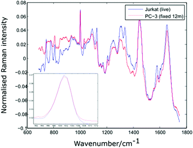 | ||
| Fig. 8 Average spectra and Phenylalanine position for live Jurkat and PC-3 cells fixed for 12 months. Average of 10 and 8 cells respectively. | ||
The spectra shown in Fig. 8 confirm that the phenylalanine peak position is identical for the live Jurkat and fixed PC-3 cells, despite the marked difference in both cell type and preparation conditions. Given the lack of evidence for any shift in the position of the 1001 cm−1 band, it is possible that for the examples quoted above, the reported shift in this peak is due to a change in experimental conditions rather than underlying biochemistry, emphasising the need to move away from traditional methods of analysis in which spectra for different cell lines are recorded at different times.
5. Conclusions
The use of low cost microfluidic flow cells for the analysis of live cells has been demonstrated. Fabrication of both the channel and upper substrate using an inexpensive commercial laser cutter allows single and multiple channel designs to be produced in high volumes at low cost.Discrimination of PC-3 and Jurkat cells at acquisition times of 5 seconds has been demonstrated, together with discrimination based on the ratio of two bands. In both cases, levels of cytochrome-c have been shown to offer a simple method of discriminating between epithelial prostate cells and lymphocytes. While cytochrome-c levels have also been shown to vary with time for live cells, additional data has shown enhanced cytochrome-c levels in the metastatic PC-3 prostate cell line, and this data will be presented in a forthcoming publication.
The dual channel device discussed in section 4 allows cells contained in two separate channels to be captured and analysed at closely-spaced intervals, and the incorporation of additional channels in future designs is straightforward. While a number of cases exist in which optical trapping, microfluidics and Raman analysis have been combined, we believe this is the first example of a fully automated system, in which the only intervention required is the addition of cells to the device. Although alternative trapping arrangements comprised of counter-propagating beams have been shown to have a number of advantages including a reduced power density within a trapped cell,15,21 such designs do not readily allow multiple channels to be incorporated. Furthermore, the use of a single high numerical aperture objective which can be moved relative to the flow channel retains the possibility of cells of interest being manipulated, as proposed by early examples of proof of principle Raman-activated cell sorting (RACS) devices.22,23
Acknowledgements
The authors gratefully acknowledge financial support from the Biotechnology and Biological Sciences Research Council (BBSRC).References
- T. J. Harvey, E. C. Faria, A. Henderson, E. Gazi, A. D. Ward, N. W. Clarke, M. D. Brown, R. D. Snook and P. Gardner, Spectral discrimination of live prostate and bladder cancer cell lines using Raman optical tweezers, J. Biomed. Opt., 2008, 13, 6 CrossRef PubMed.
- T. J. Harvey, C. Hughes, A. D. Ward, E. C. Faria, A. Henderson, N. W. Clarke, M. D. Brown, R. D. Snook and P. Gardner, Classification of Fixed Urological Cells using Raman Tweezers, J. Biophotonics, 2009, 2, 47–69 CrossRef CAS PubMed.
- U. Neugebauer, S. Dochow, C. Krafft, T. Bocklitz, J. H. Clement and J. Popp, Diagnostics of tumor cells by combination of Raman spectroscopy and microfluidics, Proc SPIE 8807, 2011 Search PubMed.
- O. M. Salazar, P. Rubin and F. R. Hendrickson, Single-dose half-body irradiation for palliation of multiple bone metastases from solid tumors. Final Radiation Therapy Oncology Group report, Cancer, 1986, 58, 29–36 CrossRef CAS PubMed.
- N. J. George, Natural history of localised prostatic cancer managed by conservative therapy alone, Lancet, 1988, 1, 494–497 CrossRef CAS.
- J. Lattouf and F. Saad, Gleason score on biopsy: is it reliable for predicting the final grade on pathology?, BJU Int., 2002, 90(7), 694–698 CrossRef PubMed.
- P. Crow, B. Barrass, C. Kendall, M. Hart-Prieto, M. Wright, R. Persad and N. Stone, The use of Raman spectroscopy to differentiate between different pro-static adenocarcinoma cell lines, Br. J. Cancer, 2005, 92(12), 2166–2170 CrossRef CAS PubMed.
- P. Crow, N. Stone, C. A. Kendall, J. S. Uff, J. A. Farmer, H. Barr and M. P. Wright, The use of Raman spectroscopy to identify and grade prostatic adenocarcinoma in vitro, Br. J. Cancer, 2003, 89(1), 106–108 CrossRef CAS PubMed.
- T. J. Harvey, E. Gazi, A. Henderson, R. D. Snook, N. W. Clarke, M. Brown and P. Gardner, Factors Influencing the Discrimination and Classification of Prostate Cancer Cells Lines by FTIR Microspectroscopy, Analyst, 2009, 134, 1083–1091 RSC.
- T. J. Harvey, A. Henderson, E. Gazi, N. W. Clarke, M. Brown, E. Correia Faria, R. D. Snook and P. Gardner, Discrimination of prostate cancer cells by reflection mode FTIR photo-acoustic spectroscopy, Analyst, 2007, 132, 292–295 RSC.
- E. Gazi, J. Dwyer, N. P. Lockyer, P. Gardner, J. H. Shanks, J.-A. Roulson, C. A. Hart, N. W. Clarke and M. D. Brown, Biomolecular Profiling of Metastatic Prostate Cancer Cells in Bone Marrow Tissue Using FTIR Microspectroscopy: A Pilot Study, Anal. Bioanal. Chem., 2007, 387, 1621–1631 CrossRef CAS PubMed.
- T. W. Friedlander and L. Fong, The End of the Beginning: Circulating Tumor Cells As a Biomarker in Castration-Resistant Prostate Cancer, J. Clin. Oncol., 2004, 32, 11 Search PubMed.
- Y. Oshima, H. Shinzawa, T. Takenaka, C. Furihata and H. Sato, Discrimination analysis of human lung cancer cells associated with histological type and malignancy using Raman spectroscopy, J. Biomed. Opt., 2010, 15(1), 017009 CrossRef PubMed.
- C. Scalfi-Happ, M. Udart, C. Hauser and A. Ruck, Investigation of lipid bodies in a colon carcinoma cell line by confocal Raman microscopy, Med. Laser Appl., 2011, 26, 152–157 CrossRef.
- S. Dochow, C. Beleites, T. Henkel, G. Mayer, J. Albert, J. Clement, C. Kraft and J. Popp, Quartz microfluidic chip for tumour cell identification by Raman spectroscopy in combination with optical traps, Anal. Bioanal. Chem., 2013, 405(8), 2743–2746 CrossRef CAS PubMed.
- S. Dochow, C. Krafft, U. Neugebauer, T. Bocklitz, T. Henkel, G. Mayer, J. Alberta and J. Popp, Tumour cell identification by means of Raman spectroscopy in combination with optical traps and microfluidic environments, Lab Chip, 2011, 11, 1484–1490 RSC.
- A. Nur-E-Kamal, S. R. Gross, Z. Pan, Z. Balklava, J. Ma and L. F. Liu, Nuclear Translocation of Cytochrome c during Apoptosis, J. Biol. Chem., 2004, 279, 24911–24914 CrossRef CAS PubMed.
- S. Fukura, T. Mizukami, S. Odake and H. Kagi, Factors Determining the Stability, Resolution, and Precision of a Conventional Raman Spectrometer, Appl. Spectrosc., 2006, 60(8), 946–950 CrossRef CAS PubMed.
- J. W. Chan, D. S. Taylor, T. Zwerdling, S. M. Lane, K. Ihara and T. Huser, Micro-Raman Spectroscopy Detects Individual Neoplastic and Normal Hematopoietic Cells, Biophys. J., 2006, 90(2), 648–656 CrossRef CAS PubMed.
- A. D. Meade, C. Clarke, F. Draux, G. D. Sockalingum, M. Manfait, F. M. Lyng and H. J. Byrne, Studies of Chemical Fixation E_ects in Human Cell Lines Using Raman Microspectroscopy, Anal. Bioanal. Chem., 2010, 396(5), 1781–1791 CrossRef CAS PubMed.
- P. R. T. Jess, V. Garces-Chavez, D. Smith, M. Mazilu, L. Paterson, A. Riches, C. S. Herrington, W. Sibbett and K. Dholakia, Dual beam fibre trap for Raman micro-spectroscopy of single cells, Opt. Express, 2006, 14(12), 5779–5791 CrossRef CAS PubMed.
- A. Y. Lau, L. P. Lee and J. W. Chan, An integrated optofluidic platform for Raman-activated cell sorting, Lab Chip, 2008, 8(7), 1116–1120 RSC.
- C. Xie, D. Chen and Y. Li, Raman sorting and identification of single living micro-organisms with optical tweezers, Opt. Lett., 2005, 30(14), 1800–1802 CrossRef PubMed.
| This journal is © The Royal Society of Chemistry 2016 |

