 Open Access Article
Creative Commons Attribution 3.0 Unported Licence
Emulsion technologies for multicellular tumour spheroid radiation assays†
Kay S.
McMillan
a,
Anthony G.
McCluskey
b,
Annette
Sorensen
b,
Marie
Boyd
b and
Michele
Zagnoni
*a
aCentre for Microsystems and Photonics, Electronic and Electrical Engineering, University of Strathclyde, Glasgow, G1 1XW, UK. E-mail: michele.zagnoni@strath.ac.uk
bStrathclyde Institute of Pharmacy and Biomedical Sciences, University of Strathclyde, Glasgow, G4 0RE, UK
First published on 5th October 2015
Abstract
A major limitation with current in vitro technologies for testing anti-cancer therapies at the pre-clinical level is the use of 2D cell culture models which provide a poor reflection of the tumour physiology in vivo. Three dimensional cell culture models, such as the multicellular spheroid, provide instead a more accurate representation. However, existing spheroid-based assessment methods are generally labour-intensive and low-throughput. Emulsion based technologies offer enhanced mechanical stability during multicellular tumour spheroid formation and culture and are scalable to enable higher-throughput assays. The aim of this study was to investigate the characteristics of emulsion-based techniques for the formation and long term culture of multicellular UVW glioma cancer spheroids and apply these findings to assess the cytotoxic effect of radiation on spheroids. Our results showed that spheroids formed within emulsions had similar morphological and growth characteristics to those formed using traditional methods. Furthermore, we have identified the effects produced on the proliferative state of the spheroids due to the compartmentalised nature of the emulsions and applied this for mimicking tumour growth and tumour quiescence. Finally, proof of concept results are shown to demonstrate the scalability potential of the technology for developing high-throughput screening assays.
1. Introduction
It has been estimated that approximately 50% of cancer patients will receive radiotherapy as part of their treatment.1,2 Although radiotherapy delivers high success rates in certain types of cancer, improvements are still required in others, such as glioblastoma, where the chance of treatment failure remains high.2 Physiologically relevant in vitro models at the preclinical stage can play a significant role in improving the efficacy of radiotherapy.3 Current models are typically based on cancer cell monolayers which provide an inadequate reflection of the tumour microenvironment in vivo4 due to a lack of variations in cell proliferative state, cell-to-cell and cell-to-matrix interactions and provide an unrealistic uniformity in access to nutrients and oxygen by cells. In contrast, tumour cells grown as 3D multicellular spheroids are more representative of in vivo tumour growth.5Within a tumour, cells that are more distant from the blood vessels become progressively quiescent (a reversible cell state where cells are frozen in the G0–G1 phase of the cell cycle), hypoxic and eventually necrotic.6,7 Utilisation of multicellular tumour spheroids of ≥200 μm in diameter enables modelling of blood vessel-free regions of tumours in vivo, mimicking the diffusional limits of molecules created by the close packing of cells within the 3D aggregate. This ultimately results in gradients of oxygen, glucose, lactate and pH from the external layer of the spheroid down to its core.8 As a consequence, the outer cellular layers of a spheroid are composed of proliferating cells, whilst their inner layers present a quiescent phenotype and, for spheroid of diameters typically greater than 400 μm, a core containing hypoxic, apoptotic and necrotic cells.8,9 Therefore, multicellular tumour spheroids represent a simplified but physiologically relevant in vitro model for radiotherapy development, also enabling the aspects of tumour heterogeneity and repopulation to be addressed.
Quiescent/hypoxic tumour cells have been shown to exhibit increased resistance to radiation and chemotherapy drugs.10 This aspect is considered multifactorial but includes increased activation of DNA repair machinery and alterations in apoptotic pathways which limits therapy and lethal damage.5 Therefore, while radiotherapy and/or chemotherapy have toxic effects on rapidly proliferating cells, the more therapy-resistant quiescent cells (within the tumour's inner layers) can enter into the actively dividing phase of the cell cycle after treatment, once renewed access to nutrients is obtained. This is a leading cause of tumour relapse. Consequently, the use of multicellular spheroids is expected to have an impact on developing more effective anticancer treatments as well as ‘bridge the gap’ between physiologically relevant in vitro models and animal models.11
Methods which have been traditionally used to form multicellular spheroids include forced floating, hanging drop, agitation based approaches (e.g. spinner flask) or via the incorporation of a matrix or scaffold.4,12,13 However, while these methods are used as standard in research labs, they are generally labour intensive, present low-medium throughput and typically produce spheroids of heterogeneous sizes.4 Therefore, novel methodologies are desirable which avoid and/or minimise these drawbacks, allowing 3D tumour models to be more widely adopted.
Emulsion-based technologies are becoming popular tools for the formation and culturing of multicellular spheroids and organoids.14–20 Such methods involve the encapsulation of cell aggregates or cell suspensions within aqueous or gel (i.e. agarose or alginate) droplets surrounded by a biocompatible and non-adherent oil-surfactant interface (i.e. using fluorinated polyethyl glycol (PEG) block-copolymers21–23). One of the attractive features of such systems is compartmentalisation, a concept where each emulsion acts as a closed vessel carrying out an environmentally isolated experiment.24 In contrast to spinner flask techniques, where a cell suspension must be kept in continuous motion to prevent cell attachment to the surface of the flask,4 cells encapsulated either into a resting droplet or an emulsion are not exposed to a shear stress, as it has been demonstrated that shear forces can hinder cell physiology, potentially impacting the effect of a treatment.25 However, when using hanging plates, exchange of medium or plate tilting can result in merging and/or detachment of hanging droplets.26 Overall, these factors have an effect on long term culture and hinder the development of higher-throughput systems.
In this study, we have investigated the potential of emulsion-based techniques for the formation and long term culture of multicellular cancer spheroids and their use for interrogating radiation toxicity as a proof of concept using either mostly proliferative or mostly quiescent spheroids, the latter providing a model for studying quiescent tumours. Using a human glioma cell line (UVW), we have characterised the growth rates of spheroids of variable size, their phenotypic features and their response to X-ray irradiation depending on the emulsion parameters. Results were compared to those achieved with spheroids formed in spinner flasks and then seeded onto low attachment plates. Finally, preliminary data is provided that demonstrate the potential for the miniaturisation of such a system in a high-throughput microfluidic format.
2. Experimental
2.1. Device preparation
Devices for both manual and microfluidic experiments were fabricated using polydimethylsiloxane (PDMS) using standard soft- and photo-lithography techniques. For manual experiments, devices consisted of a 5 mm thick layer of PDMS (Dow Corning Sylgard 184) containing open wells bonded to a microscope slide. First, a silicon wafer was silanised by vapour deposition of 1H,1H,2H,2H-perfluorooctyl-trichlorosilane (Sigma Aldrich, UK) for 1 hour. Then, PDMS was poured onto the wafer at a 10![[thin space (1/6-em)]](https://www.rsc.org/images/entities/char_2009.gif) :
:![[thin space (1/6-em)]](https://www.rsc.org/images/entities/char_2009.gif) 1 ratio of base to curing agent, degassed in a vacuum desiccator chamber and cured at 80 °C for a minimum of 2 hours. A PDMS layer was then cut from the mould and 20 wells of 8 mm in diameter were punched through the layer using a biopsy punch. Subsequently, a PDMS film (10
1 ratio of base to curing agent, degassed in a vacuum desiccator chamber and cured at 80 °C for a minimum of 2 hours. A PDMS layer was then cut from the mould and 20 wells of 8 mm in diameter were punched through the layer using a biopsy punch. Subsequently, a PDMS film (10![[thin space (1/6-em)]](https://www.rsc.org/images/entities/char_2009.gif) :
:![[thin space (1/6-em)]](https://www.rsc.org/images/entities/char_2009.gif) 1 ratio of base to curing agent) of approximately 100 μm was spin-coated over a glass slide and the punched PDMS layer was assembled on the fresh PDMS film. The structure was cured at 80 °C for an hour before use.
1 ratio of base to curing agent) of approximately 100 μm was spin-coated over a glass slide and the punched PDMS layer was assembled on the fresh PDMS film. The structure was cured at 80 °C for an hour before use.
For microfluidic experiments, master templates were produced using SU8 photoresist (3000 series, MicroChem, US) onto a silicon wafer following the manufacturer's protocol, achieving a final resist thickness of 200 μm. The resist was exposed through a photomask (JD Photo-Tools, UK) to UV light and was developed in MicroPosit EC solvent (Rohm and Haas, US). To prevent PDMS adhesion to the resulting silicon master, the silicon surface was silanised by vapour deposition of 1H,1H,2H,2H-perfluorooctyl-trichlorosilane (Sigma Aldrich, UK) for 1 hour. PDMS was then poured onto the silicon master at a 10![[thin space (1/6-em)]](https://www.rsc.org/images/entities/char_2009.gif) :
:![[thin space (1/6-em)]](https://www.rsc.org/images/entities/char_2009.gif) 1 ratio of base to curing agent, degassed in a vacuum desiccator chamber and cured at 80 °C for 2 hours. The PDMS devices were then peeled from the mould, cut to the desired size, and holes were punched using G21 biopsy needles to obtain the inlet and outlet wells for each chamber. PDMS devices were then cleaned and irreversibly bonded to glass microscope slides using oxygen plasma. Bonded devices were then treated with undiluted Aquapel (PPG Industries) to obtain fluorophilic channel surfaces.
1 ratio of base to curing agent, degassed in a vacuum desiccator chamber and cured at 80 °C for 2 hours. The PDMS devices were then peeled from the mould, cut to the desired size, and holes were punched using G21 biopsy needles to obtain the inlet and outlet wells for each chamber. PDMS devices were then cleaned and irreversibly bonded to glass microscope slides using oxygen plasma. Bonded devices were then treated with undiluted Aquapel (PPG Industries) to obtain fluorophilic channel surfaces.
2.2. Cell culture and spheroid formation
A human glioblastoma cell line (UVW) which was developed in house was utilised.27 UVW cells were maintained in an atmosphere of 5% CO2 and incubated at 37 °C, in minimum essential medium (MEM), containing 10% (v/v) of foetal calf serum (FCS), L-glutamine (200 mmol l−1), penicillin/streptomycin (100 U ml−1) and fungizone (2 μg ml−1). Medium and additional supplements were purchased from Invitrogen, UK.To form spheroids within medium in oil (M/O) droplets in open-well devices, 60 μl of FC-40 (3 M) fluorinated oil with 2 wt% block copolymer fluorosurfactants (designed by the Weitz Group at Harvard and supplied by RAN Biotechnologies, catalogue# 008-FluoroSurfactant, Beverly, MA, USA) was added to each well. Subsequently, a cell suspension ranging 40–104 cells per ml was manually pipetted into the wells in droplet volumes of 25–100 μl of medium depending on the experimental purpose. For experiments interrogating the effect of irradiation on spheroids, droplets of 100 μl were used and the medium was refreshed every two days (for a maximum of 28 days) by exchanging 50 μl in each droplet using a pipette.
As a comparison, spheroids were also formed using the conventional method of preparation in magnetic spinner flasks, by seeding 1 × 10⁶ cells into 75 ml of medium and then incubating, on a magnetic stirrer, at an atmosphere of 5% CO2 at 37 °C for 3 days. Spheroids were then manually selected and individually transferred into wells of a 96 well low attachment plate using a Gilson pipette (Corning Costar) and incubated for up to 28 days, with each well containing 200 μl of medium which was refreshed every 2 days.
Finally, to investigate the miniaturisation and high-throughput scalability of emulsion-based assays for multicellular spheroid culture, microfluidic devices were used. M/O droplets (∼7 nl), encapsulating a UVW cell suspension, were formed at a T-junction and stored within a device containing an array of approximately 2000 droplets. FC-40 (3 M) fluorinated oil with 2 wt% block copolymer and a cell suspension (5 × 10⁶ cells per ml in medium) were used as the continuous and dispersed phases, respectively. PTFE (polytetrafluoroethylene) tubing (Cole Parmer) were used to connect syringes to the inlet ports of the microfluidic device (the microchannel topology was based on a previously reported design28) and syringe pumps were used to inject the phases. In this instance, medium was not refreshed and devices were incubated after seeding at an atmosphere of 5% CO2 and at 37 °C.
2.3. Spheroid growth measurement
Spheroid growth was monitored by measuring the increase of the multicellular aggregate diameter over time from brightfield images, acquired using a Zeiss inverted microscope (Axiovert A1) with a Labview controlled Dalsa Genie CMOS HM1024 camera. Spheroid dimensions were estimated using ImageJ by measuring the longest and shortest diameters (D1 and D2, respectively). These values were then used to calculate the approximated volume (V) of each spheroid, estimated as . A comparison analysis between the results from spheroid irradiation and control experiments (no irradiation) was performed calculating the area under the curve V(t)/V0 (where V(t) is the spheroid volume measured at each time point and V0 is its initial volume) for each spheroid. The Mann Whitney and Kruskal Wallis tests were used to evaluate the statistical difference between experiments (significant difference between groups obtained for p value ≤0.05).
2.4 Sectioning and staining of spheroids
Approximately 50 spheroids were collected for each manual droplet-based (3 devices/experiment) and spinner flask experiments and fixed in 10% formalin for a minimum of 12 hours. Once fixed, the spheroids were tissue-processed before embedding them within a wax block. Blocks containing spheroids were then sectioned using a microtome (Leica RM2125RTE) to form 4 μm thick sections which were mounted on polysine coated slides ready for staining.For haematoxylin and eosin staining, the sections were first de-waxed in histoclear (National Diagnostics) and re-hydrated by successive immersions in 100% (v/v) ethanol, 70% (v/v) ethanol and water. The staining procedure involved immersions in haematoxylin for 7 min, 1% (v/v) acid alcohol, Scotts tap water and eosin with intermediate washes in water. The stained sections were then dehydrated in 70% (v/v) and 100% (v/v) ethanol and immersed in histoclear before applying mounting media (Histomount, National Diagnostics) and a coverslip.
2.5. Viability staining of spheroids
Live spheroids from droplet-based experiments were stained for viability using fluorescein diacetate (FDA) and propidium iodide (PI) (Sigma Aldrich). Although spheroids could be stained within emulsions, for ease of procedure, these were typically extracted from the droplets and washed with phosphate buffered saline (PBS). Spheroids were then incubated with staining solution containing 20 μg ml−1 of PI and 8 μg ml−1 of FDA for approximately 20 minutes. The staining solution was then washed off and replaced with PBS before imaging.2.6. Spheroid irradiation
Spheroids were allowed to form and cultured in M/O droplets and irradiated with either a single dose of 4 Gy or 8 Gy using a PXI X-Rad 225C X-irradiator with the dose rate per min equating to 2.2 Gy per min (RPS Services, Surrey, UK). Subsequently, both control and irradiated spheroids were cultured and their size monitored for up to 28 days.3. Results
Experiments were carried out firstly to characterise the formation and long-term culture of multicellular spheroids in emulsion-based systems. The utility of the system for analysis of irradiation on spheroid growth was then examined by interrogation of the effect of X-ray irradiation (as a model treatment) on single spheroids encapsulated in M/O droplets. Results were compared to those obtained by similarly treated spheroids but cultured in low attachment well plates. Finally, the scalability and miniaturisation of the developed procedures were tested using a microfluidic system.3.1. Formation of spheroids in M/O droplets
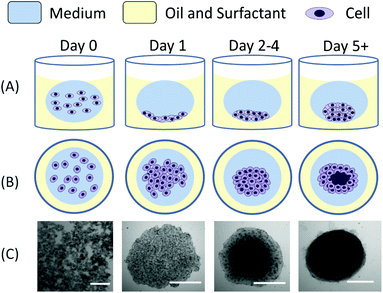
Droplets containing a specific concentration of cells in suspension were dispensed in a well previously filled with an oil–surfactant mixture using a pipette. As the oil phase was denser than the aqueous phase, the droplet floated at the top of the oil layer within the well, forming a spherical/ellipsoidal medium–oil interface (Fig. 1). Due to the biocompatible and non-adherent nature of polyethylglycol-surfactants used, the water–oil interface was inert and provided an appropriate condition for cell aggregation. Immediately after dispensing, cells sedimented to the bottom of the droplet at the oil–surfactant–medium interface.Cells aggregated within the first 12–24 hours to form a flat layer of cells (Fig. 1, day 1) at the bottom of the droplet. Progressively, from day 2 onwards, the cell aggregate structures became more tightly packed with cells clustering on top of each other until formation of a dense, almost spherical structure (Fig. 1, day 5). The time that was required for the cellular aggregates to form a compact structure depended critically upon the initial cell concentration used. No significant difference in the formation process was observed for spheroids with a size ranging from 10s to 100s of μm in diameter.
3.2. Investigation of the parameters determining spheroid growth in M/O droplets
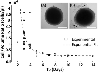
A range of droplet volumes (25–100 μl), encapsulating cell suspensions of different concentrations, were tested to determine the effect on spheroid formation and long-term culture due to the finite volume of medium present within the droplets, a condition that is expected to limit the total amount of nutrients inside a droplet and the diffusion of cell waste products. Spheroid growth was monitored over time, without media replenishment, using brightfield microscopy to estimate the time period within which no apparent detrimental signs or growth inhibition were observed, identified as: (1) the time point, TD, at which spheroid disaggregation was detected, defined as the condition where the first cell debris were observed around the spherical compact spheroid structure (arrows in Fig. 2B); (2) the period of time, TG, over which spheroid growth plateaued without disaggregation (Fig. 3). Cells which disaggregated from a compact spheroid were no longer viable as confirmed by live/dead staining (Fig. S1†).An approximated exponential relationship between the number of encapsulated cells per droplet volume (cells per μl) and TD was identified (Fig. 2). As expected, without medium exchange, spheroids remained longer in a compact aggregated structure for progressively larger droplet volumes. In addition, even though the devices were stored in a humidified environment within the incubator, it was observed that the droplet volume reduced over time due to evaporation, resulting potentially in a difference in the concentrations of salts and pH within the encapsulated medium.
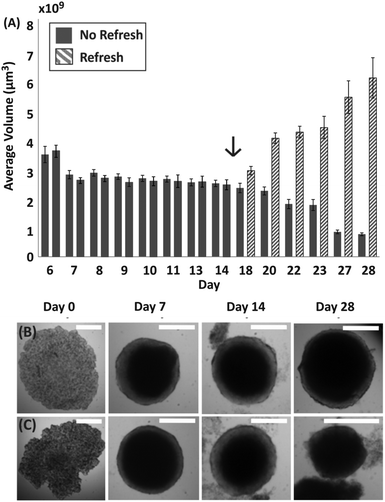
To further investigate the condition of spheroids within droplets during culture when no medium was exchanged, spheroids were formed with a ratio of approximately 500 cells per μl (following the trend identified in Fig. 2, estimated TD ∼ 10 days). In this case, it was observed that the change in spheroid size was negligible between approximately 7 and 11 days after seeding (TG ∼ 4 days in Fig. 3A), with the first signs of disaggregation observed for some spheroids on day 9. Before day 7 the cellular aggregates had not yet reached a compact spheroid-like structure, as describe in Fig. 1. On day 14 of culture, a considerable amount of cells were observed to have detached from the spheroids (Fig. 3B and C) and the integrity of the 3D cellular structure became increasingly compromised. Finally, to determine whether the cells within the compact spheroid structure could proliferate after being in this compromised state, an experiment was performed where medium was refreshed on day 15 for half of the spheroids in the same device (with medium exchanged every two days), while the remaining half was kept in the same unchanged condition. Only in the case of medium exchange did the spheroids increase in size (Fig. 3A and day 28 in Fig. 3B), while the remaining ones continued to lose integrity, accumulating an increasing amount of cell debris within the droplet (Fig. 3A and day 28 in Fig. 3C).
3.3. Determination of impact of droplet culture on uniformity of spheroid size
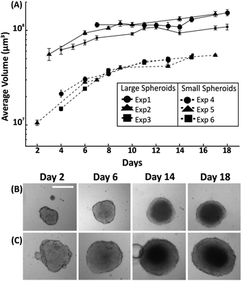
Having established the effect of medium refreshment on spheroid growth within droplets, the uniformity in spheroid size and growth rate was investigated for variable initial cell seeding concentrations. In this instance, medium was refreshed in each droplet every two days by exchanging approximately 50% of the droplet content. Spheroid growth was monitored over 18 days, with the first significant measurement being the one at which the cell aggregate reached a minimum size after seeding (due to the cell aggregating process – as described in section 3.1). A cell number of either 500 cells or 1500 cells into medium were dispensed when forming droplets of 100 μl, leading to formation of spheroids with an initial diameter of ∼300 μm (∼day 3 after seeding) and ∼575 μm (∼day 6 after seeding), respectively. Two growth patterns were identified with the smallest size spheroids presenting a faster growth rate (∼50% increase in diameter over initial value) in the first 8 days of culture in comparison to the larger spheroids (∼25% increase in diameter over initial value). Following this period, in both cases the growth rate of the spheroids was approximately 6 μm per day of increase in diameter (Fig. 4).3.4. Investigation of spheroid morphology
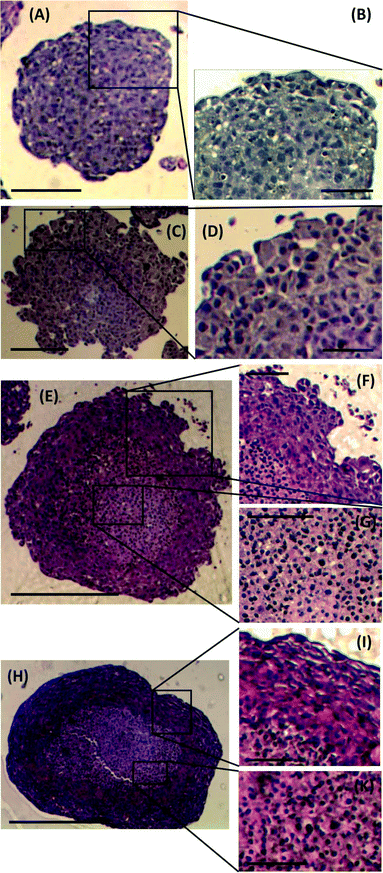
To investigate any morphological differences between spheroids formed using the proposed M/O droplet technique and those obtained from conventional spinner flask techniques, spheroid sections were prepared, stained and analysed to determine changes in spheroid architecture and organisation. Spheroids of comparable size and days of culture from both techniques, ranging from 300 μm (5 days culture) to 750 μm (18–21 days culture) in diameter, were compared (Fig. 5). Spheroids formed after 5 days of culture from either droplets or spinner flasks, presented similar characteristics in term of cell packing, internal cohesion and nuclei size (Fig. 5A and C). A considerable difference was instead identified between the two families of spheroids only for cells at their outer layers, where spheroids from spinner flasks lacked a smooth and compact border (Fig. 5B and D).For larger spheroids, a morphological difference was observed compared to the smaller ones, as two distinct areas within the stained sections were identified (Fig. 5E and H): cells in the outer layer were more tightly packed than within the core. As a consequence, the cell nuclei in the core were more spherical than those in the outer rim, as also previously reported by Rajcevic et al. who observed the tight packing of cells within the spheroid and difference in shape of nuclei as a result.29
3.5. Comparison of irradiation effects on spheroid growth parameters
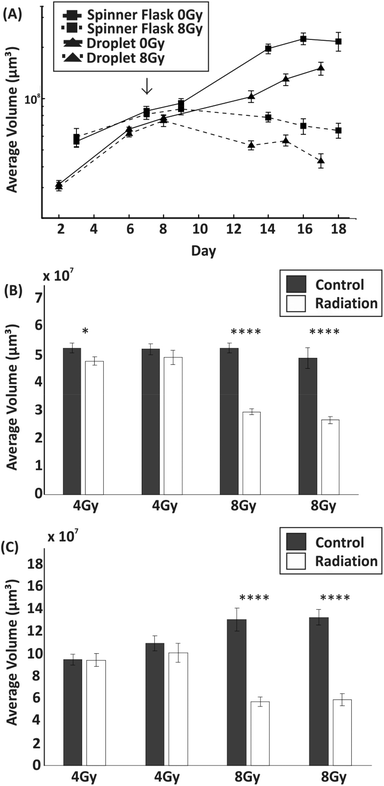
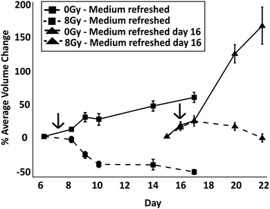
The toxicity induced by X-ray irradiations on spheroids of similar size (average diameter ∼450 μm) obtained from droplets and spinner flasks was compared (although spheroid size variability using a spinner flask was higher than with those formed in droplets). Spheroids were typically treated with 8 Gy of radiation on day 7 of culture. In comparison to non-irradiated control spheroids, irradiation with 8 Gy induced a significant reduction in their growth when formed both within droplets (p < 0.01) and within a non-adherent plate (p < 0.0001) (Fig. 6). Live/dead cell staining showed, qualitatively, that irradiation effects progressively induced cell death over time with respect to the control, with a considerable decrease in spheroid size (Fig. S2†). No significant difference in the growth of spheroid before and after radiation was observed that was dependent on the technique used for spheroid formation and culture. A further experiment was carried out to determine the effect on spheroid growth following exposure to two different doses of radiation (4 Gy and 8 Gy) on spheroids of different size ranges (Fig. 6B and C). A dose of 8 Gy induced a significant reduction in size for both large and small spheroids compared to the control (p < 0.0001 for each experiment), leading to a volume difference of −44% for small spheroids and −55% for large spheroids. Conversely, 4 Gy irradiation induced little or no significant growth perturbation with respect to the control group.To identify whether spheroids in a ‘dormant’ state were more radioresistant than those in a proliferative state, radiation experiments were carried out with spheroids in droplets where medium was either exchanged regularly from the start of the culture or was not exchanged until the day of irradiation. To determine when the dormant state had been induced, spheroid size was monitored until the first signs of cell detachment were observed (TD = 16 days in this experiment) and live/dead cell staining performed, correlating spheroid growth with cell viability (Fig. S1 and S2 in ESI†). After irradiation, medium was regularly refreshed as per the control experiments. To ensure that control spheroids were in a proliferative state, these were irradiated on day 7 of culture (according to results in Fig. 2A). The spheroids in both conditions were treated with radiation when they were of a similar size. To assess the response between the two cases, the percentage difference of the average spheroid volume after treatment with 8 Gy with respect to their size before irradiation was plotted (Fig. 7). In addition, with respect to the case of spheroids having media being regularly refreshed, live/dead cell staining showed, qualitatively, a reduced efficacy of irradiation both on spheroid growth and death when those were kept in a less thriving environment (Fig. S2†).
A one way ANOVA test was carried out to identify differences between the percentage volume change on day 4 post irradiation treatment between the control and irradiated groups. A significant difference was observed between spheroids which were refreshed and those which were not (p < 0.0001 between dashed lines in Fig. 7). The results show that irradiation had a more significant impact on reducing the spheroid size when the multicellular aggregates were in a nutrient rich environment than when in a dormant condition where medium had not been refreshed (as previously shown in Fig. 3, after medium was refreshed in droplets containing control dormant spheroids, these quickly recovered their growth). In both cases, the comparison between control and radiation experiments (for both medium exchange and no medium exchange) produces a significant difference (p < 0.0001 for each experiment), suggesting that the radiation impacts spheroid growth regardless of their proliferative status. In addition, the spheroids grown in a low nutrient environment were observed to grow at a faster rate when replenished with medium in comparison to those with constant refreshment (p < 0.0001). This suggests that, compared to nutrient-rich cells, dormant cells were not only more resistant to radiation, but also exhibited a more aggressive phenotype upon re-exposure to nutrients.
3.6. Assay scalability using droplet microfluidics
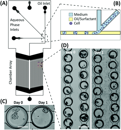
Preliminary experiments were performed using droplet microfluidics to investigate the miniaturisation and scalability opportunities of the presented emulsion technology for developing spheroid-based assays. The device structure was based on the design by Schmitz et al.,28 containing a chamber array that allows for the trapping and storage of M/O droplets encapsulating cells. Droplets were produced via a T-junction geometry and then stored within an array of 2128 chambers (Fig. 8). The microfluidic structure allows droplets to remain trapped in the round-shaped microchannels within the chamber,30 each droplet being separated from one another by a layer of oil to prevent coalescence and facilitate long-term storage. Typically, the droplet trapping efficiency was ∼68%, with the percentage of droplets containing multiple cells varying from 60% to 95% depending on the cell concentration used. Once multiple cells were encapsulated within droplets, the aggregation process occurred as in the macroscopic droplets forming compact spheroids within 12–24 hours depending upon the initial cell number within the droplet. However, due to the current structure of the device, the medium within the droplets could not be refreshed. Consequently, the lifetime of the spheroids was 3–4 days, according to the trend identified in Fig. 2.4. Discussion
Multicellular tumour spheroids could be formed within M/O droplets and the time taken for cell to aggregate from a flat monolayer to an ellipsoidal 3D structure depended upon the initial cell number encapsulated in the droplet. This is consistent with previous reports where spheroids have been formed using double emulsion techniques14 or microcapsules.20 However, in contrast to previous publications, we used single emulsions and identified the parameters that allow us to culture spheroids over a long period of time. Furthermore, we have capitalized on emulsion compartmentalization for the creation of in vitro tumour quiescent models.The compartmentalised aspects of the proposed emulsion-based system are similar to those obtained in a hanging droplet system.32 However, M/O droplets have the advantage of being unaffected by vibration, mechanical shocks or tilting of the plate. These issues are known to compromise the stability of water-in-air droplets hanging from the plastic anchor sites, which ultimately result in droplet detachment from the plate. The robustness to handling and transporting M/O droplet plates derives from the support that the denser oil layer provides to the floating (water-based) droplets and the interfacial tension properties of the phases. These allow spheroid containing droplets to easily move within the well, without compromising spheroid integrity and the emulsion interface stability, even when transporting the device.
Spheroids from M/O droplets had a similar morphology and phenotypic characteristics to those produced using traditional methods (i.e. spinner flask and low adhesion plates). As consistently reported in the literature, with a progressive increase in the spheroid size, gradients of nutrients and oxygen are formed from the outside to the core of the 3D multicellular structure, a condition that affects growth rate, cell proliferation and spheroid size. As apparent from the sections (Fig. 5), spheroids grown to a diameter larger than 500 μm presented a clear difference between the inner and outer layers.8 The outer cells presented more oblong shaped nuclei than those in the core of the spheroid which were more spherical in shape, suggesting a difference in the packing of cells. The growth curve of the spheroids formed in M/O droplets showed a similar trend to those of UVW cell spheroids by Neshasteh-Riz et al. (1997)33 where forced floating methods were used. A reduction in the growth rate over time is expected when a spheroid increases in size, as it becomes denser due to the higher cell number and a higher proportion of cells within the spheroid are starved of the nutrients necessary for division.12
An important factor which was considered in this study was to identify the conditions required for the long term culture of spheroids within droplets, as cancer assays may be required to be conducted for up to 4 weeks in order to determine whether a treatment is cytostatic or cytotoxic and to be comparable with in vivo studies.34–36 Any compartmentalised environment is naturally associated with a limited amount of nutrient (which affects the temporal availability of resources) and also with accumulation of waste product (due to the cell metabolic activity). Within a finite volume of medium, the proliferating cells in the outer layer of the spheroid will be exposed to progressively less nutrients and more toxic metabolites, greatly affecting their condition and inducing first a dormant state, followed by increased cell death and disaggregation. Tumour cells are known to consume a high amount of glucose, in order to produce ATP and to meet the requirements for proliferation.37 In contrast to normal cells, which rely upon oxidative phosphorylation to provide the products required for proliferation, when tumour cells undergo proliferation they carry out glycolysis.37,38 Glycolysis is advantageous to highly proliferative cells as it results in a higher rate of glucose production in comparison to oxidative phosphorylation.39 Furthermore, the breakdown of glucose for harvesting energy also produces products required for the synthesis of essential biomolecules such as lipids, amino acids and nucleotides.38 When there is a reduction in the availability of glucose, such as the environment created when medium is not refreshed in a droplet, the cells undergo a transition into a quiescent state for a period of time and, if no extra nutrients are provided, they will then undergo apoptosis.38 The high consumption of nutrients required for tumour cell proliferation means that compartmentalisation is an important factor to consider when developing encapsulation based technologies for long term spheroid culture. However, optimum exchange rate of medium would depend on the metabolic activity of the cancer cell type under investigation.
In other studies involving miniaturisation and the encapsulation of cells within microdroplets, beads or microcapsules, the duration of cell incubation varied between as little as 2 days to up to 12 days14–18,20,40 and cell viability in droplets was reduced over hours rather than days or weeks.14–20,31 The ability to extend the temporal duration of the assay whilst controlling the spheroid size and its proliferation/quiescent state can be useful for mimicking different tumour condition (i.e. relapse) when investigating the efficacy of a treatment and the limitations with therapy screening assays.36 Additionally, the use of single emulsions rather than double emulsions facilitates operational procedures.
Quiescent cells are known to be more radioresistant than cells in a proliferative state.5,41–44 Results from this study showed that there was less irradiation-induced toxicity in quiescent cells in comparison to proliferative cells. From other studies it has been hypothesized that the quiescent cells have a greater ability with respect to proliferating cells to initiate repair of potentially lethal damage (such as those caused to DNA by radiation41) and these mechanisms could be responsible for the observed differences in radiation-induced toxicity. Emulsion-based systems allows for these characteristics to be investigated and applied to both radiotherapy and chemotherapy. However, in the case of chemotherapy, drugs can partition into the oil phase depending on their degree of solubility.45 This represents a limitation with the described emulsion methodology which can nonetheless be solved via calibration and implementation of a perfusion system.
The use of M/O droplet system for radiotherapeutic assays was tested on UVW glioma cell line as these are known to be radioresistant. Boyd et al. (2000)27 have previously demonstrated that UVW cells, grown as a monolayer, were moderately resistant to irradiation with approximately 56% cells surviving after delivery of a 2 Gy dose. Therefore, it is expected that due to the variation in cell proliferation rates, hypoxia and the proportion of non-proliferating cells in larger 3D spheroids, the radiation dose required to inhibit growth would be larger. This was confirmed in these studies, as for spheroids ranging from 300 to 700 μm in diameter, a dose of 4 Gy had little if no significant effect on spheroid growth in the short term after irradiation (Fig. 7). Conversely, a dose of 8 Gy induced approximately a 50% reduction in spheroid size one week after treatment.
Finally, proof of concept data with our microfluidic experiments demonstrates the potential of emulsion based techniques to be used for high-throughput screening assays. In comparison to hanging drop plates where the highest number of drops per device is currently limited to 384, miniaturisation of emulsion control in microfluidics offers a much higher throughput (1276 spheroids were formed per device in our prototypes). Further work is currently undergoing in our labs to implement regular medium exchange in the microfluidic platform, this condition being necessary to extend the lifetime and the functionality of the miniaturised assay.
5. Conclusion
In this work, we have characterised the use of emulsion technology for the development of assays based on multicellular tumour spheroids, investigating the key parameters that enable controlled spheroid formation and the conditions that support long-term culture. We have characterised the conditions that allow us to control the level of cell proliferation and quiescence in a multicellular tumour spheroid and used this in establishing the effect induced by radiotherapy on spheroid growth according to their size and irradiation dose. Furthermore, preliminary experiments have been conducted using droplet microfluidic techniques to demonstrate the feasibility of scaling spheroid based assays to a high throughput format. The implementation of medium perfusion in such a miniaturised platform has potential to open the way to large-scale testing of combination therapeutics and use with biopsy samples.Acknowledgements
The authors would like to thank the Engineering and Physical Science Research Council (EPSRC) (EP/K503174/1, EP/J501554/1) and the University of Strathclyde for financial support.References
- G. Delaney, S. Jacob, C. Featherstone and M. Barton, The role of radiotherapy in cancer treatment: Estimating optimal utilization from a review of evidence-based clinical guidelines, Cancer, 2005, 104, 1129–1137 CrossRef PubMed.
- A. C. Begg, F. a. Stewart and C. Vens, Strategies to improve radiotherapy with targeted drugs, Nat. Rev. Cancer, 2011, 11, 239–253 CrossRef CAS PubMed.
- J. Kahn, P. J. Tofilon and K. Camphausen, Preclinical models in radiation oncology, Radiat. Oncol., 2012, 7, 223 CrossRef PubMed.
- S. Breslin and L. O'Driscoll, Three-dimensional cell culture: the missing link in drug discovery, Drug Discovery Today, 2013, 18, 240–249 CrossRef CAS PubMed.
- C. Dubessy, J. M. Merlin, C. Marchal and F. Guillemin, Spheroids in radiobiology and photodynamic therapy, Crit. Rev. Oncol. Hematol., 2000, 36, 179–192 CrossRef CAS PubMed.
- O. Trédan, C. M. Galmarini, K. Patel and I. F. Tannock, Drug resistance and the solid tumor microenvironment, J. Natl. Cancer Inst., 2007, 99, 1441–1454 CrossRef PubMed.
- P. Vaupel, F. Kallinowski and P. Okunieff, Blood flow, oxygen and nutrient supply, and metabolic microenvironment of human tumors: a review, Cancer Res., 1989, 49, 6449–6465 CAS.
- F. Hirschhaeuser, et al., Multicellular tumor spheroids: an underestimated tool is catching up again, J. Biotechnol., 2010, 148, 3–15 CrossRef CAS PubMed.
- L. a. Kunz-Schughart, J. P. Freyer, F. Hofstaedter and R. Ebner, The use of 3-D cultures for high-throughput screening: the multicellular spheroid model, J. Biomol. Screening, 2004, 9, 273–285 CrossRef CAS PubMed.
- B. Desoize and J. Jardillier, Multicellular resistance: a paradigm for clinical resistance?, Crit. Rev. Oncol. Hematol., 2000, 36, 193–207 CrossRef CAS PubMed.
- K. M. Yamada and E. Cukierman, Modeling tissue morphogenesis and cancer in 3D, Cell, 2007, 130, 601–610 CrossRef CAS PubMed.
- L. A. Kunz-schughart, M. Kreutz and R. Knuechel, Multicellular spheroids: a three-dimensional in vitro culture system to study tumour biology, Int. J. Exp. Pathol., 1998, 1–23 CAS.
- J. Friedrich, C. Seidel, R. Ebner and L. a. Kunz-Schughart, Spheroid-based drug screen: considerations and practical approach, Nat. Protoc., 2009, 4, 309–324 CrossRef CAS PubMed.
- H. F. Chan, et al., Rapid formation of multicellular spheroids in double-emulsion droplets with controllable microenvironment, Sci. Rep., 2013, 3, 3462 Search PubMed.
- S. Yoon, J. A. Kim, S. H. Lee, M. Kim and T. H. Park, Droplet-based microfluidic system to form and separate multicellular spheroids using magnetic nanoparticles, Lab Chip, 2013, 13, 1522–1528 RSC.
- L. Yu, M. C. W. Chen and K. C. Cheung, Droplet-based microfluidic system for multicellular tumor spheroid formation and anticancer drug testing, Lab Chip, 2010, 10, 2424–2432 RSC.
- C. Kim, et al., Generation of core–shell microcapsules with three-dimensional focusing device for efficient formation of cell spheroid, Lab Chip, 2011, 11, 246–252 RSC.
- Y. Wang and J. Wang, Mixed hydrogel bead-based tumor spheroid formation and anticancer drug testing, Analyst, 2014, 139, 2449–2458 RSC.
- S. Sakai, et al., Cell-enclosing gelatin-based microcapsule production for tissue engineering using a microfluidic flow-focusing system, Biomicrofluidics, 2011, 5, 13402 CrossRef PubMed.
- K. Alessandri, et al., Cellular capsules as a tool for multicellular spheroid production and for investigating the mechanics of tumor progression in vitro, Proc. Natl. Acad. Sci. U. S. A., 2013, 110, 14843–14848 CrossRef CAS PubMed.
- D. J. Holt, R. J. Payne and C. Abell, Synthesis of novel fluorous surfactants for microdroplet stabilisation in fluorous oil streams, J. Fluorine Chem., 2010, 131, 398–407 CrossRef CAS.
- C. Holtze, et al., Biocompatible surfactants for water-in-fluorocarbon emulsions, Lab Chip, 2008, 8, 1632–1639 RSC.
- J. Clausell-Tormos, et al., Droplet-based microfluidic platforms for the encapsulation and screening of Mammalian cells and multicellular organisms, Chem. Biol., 2008, 15, 427–437 CrossRef CAS PubMed.
- A. B. Theberge, et al., Microdroplets in microfluidics: an evolving platform for discoveries in chemistry and biology, Angew. Chem., Int. Ed., 2010, 49, 5846–5868 CrossRef CAS PubMed.
- R.-Z. Lin, R.-Z. Lin and H.-Y. Chang, Recent advances in three-dimensional multicellular spheroid culture for biomedical research, Biotechnol. J., 2008, 3, 1172–1184 CrossRef CAS PubMed.
- A. Y. Hsiao, Y. C. Tung, C. H. Kuo, B. Mosadegh, R. Bedenis, K. J. Pienta and S. Takayama, Micro-Ring Structures Stabilize Microdroplets to Enable Long Term Spheroid Culture in 384 Hanging Drop Array Plates, Biomed. Microdevices, 2012, 14, 313–323 CrossRef CAS PubMed.
- M. Boyd, A. Livingstone, L. E. Wilson, E. M. Marshall, A. G. McCluskey, R. J. Mairs and T. E. Wheldon, Dose–response relationship for radiation-induced mutations at micro- and minisatellite loci in human somatic cells in culture, Int. J. Radiat. Biol., 2000, 76, 169–176 CrossRef CAS PubMed.
- C. H. J. Schmitz, A. C. Rowat, S. Köster and D. a. Weitz, Dropspots: a picoliter array in a microfluidic device, Lab Chip, 2009, 9, 44–49 RSC.
- U. Rajcevic, et al., Colorectal cancer derived organotypic spheroids maintain essential tissue characteristics but adapt their metabolism in culture, Proteome Sci., 2014, 12, 39 CrossRef PubMed.
- C. N. Baroud, F. Gallaire and R. Dangla, Dynamics of microfluidic droplets, Lab Chip, 2010, 10, 2032–2045 RSC.
- F. Chen, et al., Chemical transfection of cells in picoliter aqueous droplets in fluorocarbon oil, Anal. Chem., 2011, 83, 8816–8820 CrossRef CAS PubMed.
- Y.-C. Tung, et al., High-throughput 3D spheroid culture and drug testing using a 384 hanging drop array, Analyst, 2011, 136, 473–478 RSC.
- a. Neshasteh-Riz, et al., Incorporation of iododeoxyuridine in multicellular glioma spheroids: implications for DNA-targeted radiotherapy using Auger electron emitters, Br. J. Cancer, 1997, 75, 493–499 CrossRef CAS PubMed.
- C. Wang, X. Tong and F. Yang, Bioengineered 3D Brain Tumor Model To Elucidate the Effects of Matrix Stiffness on Glioblastoma Cell Behavior Using PEG-Based Hydrogels, Mol. Pharm., 2014, 11, 2115–2125 CrossRef CAS PubMed.
- J. Chen, L. Yang, E. Liu, W. He and J. Gu, Proteomic Comparison of 3D and 2D Glioma Models Reveals Increased HLA-E Expression in 3D Models is Associated with Resistance to NK Cell-Mediated Cytotoxicity, J. Proteome Res., 2014, 13, 2272–2281 CrossRef PubMed.
- O. Rixe and T. Fojo, Is cell death a critical end point for anticancer therapies or is cytostasis sufficient?, Clin. Cancer Res., 2007, 13, 7280–7287 CrossRef CAS PubMed.
- R. G. Jones and C. B. Thompson, Tumor suppressors and cell metabolism: a recipe for cancer growth, Genes Dev., 2009, 537–548, DOI:10.1101/gad.1756509.GENES.
- R. J. DeBerardinis, J. J. Lum, G. Hatzivassiliou and C. B. Thompson, The biology of cancer: metabolic reprogramming fuels cell growth and proliferation, Cell Metab., 2008, 7, 11–20 CrossRef CAS PubMed.
- M. Guppy, E. Greiner and K. Brand, The role of the Crabtree effect and an endogenous fuel in the energy metabolism of resting and proliferating thymocytes, Eur. J. Biochem., 1993, 99, 95–99 CrossRef.
- S. Sugaya, M. Yamada and M. Seki, Manipulation of cells and cell spheroids using collagen hydrogel microbeads prepared by microfluidic devices, 2012 International Symposium on Micro-NanoMechatronics and Human Science (MHS), 2012, pp. 435–438. DOI:10.1109/MHS.2012.6492486.
- A. Rodriguez, E. L. Alpen, M. Mendonca and R. J. DeGuzman, Recovery from potentially lethal damage and recruitment time of noncycling clonogenic cells in 9L confluent monolayers and spheroids, Radiat. Res., 1988, 114, 515–527 CrossRef CAS PubMed.
- H. R. Mellor, D. J. P. Ferguson and R. Callaghan, A model of quiescent tumour microregions for evaluating multicellular resistance to chemotherapeutic drugs, Br. J. Cancer, 2005, 93, 302–309 CrossRef CAS PubMed.
- W. Senkowski, et al., Three-Dimensional Cell Culture-Based Screening Identifies the Anthelmintic Drug Nitazoxanide as a Candidate for Treatment of Colorectal Cancer, Mol. Cancer Ther., 2015, 14, 1504–1516 CrossRef CAS PubMed.
- D. Khaitan, S. Chandna, M. B. Arya and B. S. Dwarakanath, Establishment and characterization of multicellular spheroids from a human glioma cell line; Implications for tumor therapy, J. Transl. Med., 2006, 4, 12 CrossRef PubMed.
- Y. Chen, et al., Characterization of sensitivity and specificity in leaky droplet-based assays, Lab Chip, 2012, 12, 5093–5103 RSC.
Footnote |
| † Electronic supplementary information (ESI) available. See DOI: 10.1039/c5an01382h |
| This journal is © The Royal Society of Chemistry 2016 |

