 Open Access Article
A RET-supported logic gate combinatorial library to enable modeling and implementation of intelligent logic functions†
Ru-Ru
Gao
,
Shuo
Shi
*,
Ying
Zhu
,
Hai-Liang
Huang
and
Tian-Ming
Yao
*
Shanghai Key Laboratory of Chemical Assessment and Sustainability, Department of Chemistry, Tongji University, Shanghai, 200092, P. R. China. E-mail: shishuo@tongji.edu.cn; tmyao@tongjji.edu.cn
First published on 23rd November 2015
Abstract
Boolean logic gates integrate multiple digital inputs into a digital output. Among these, logic gates based on nucleic acids have attracted a great deal of attention due to the prospect of controlling living systems in the way we control electronic computers. Herein, by employing Thioflavin T (ThT) as a signal transducer, we integrated multiple components based on RET (a type of proto-oncogene) into a logic gate combinatorial library, including basic logic gates (NOR, INHIBIT, IMPLICATION), a single three-input NOR gate, and combinatorial gates (INHIBIT–OR, NOT–AND–NOR). In this library, gates were connected in series where the output of the previous gate was the input for the next gate. Subsequently, by taking advantage of the library, some intelligent logic functions were realized. Expectedly, a biocomputing keypad-lock security system was designed by sequential logic operations. Moreover, a parity checker which can identify even numbers and odd numbers from natural numbers was established successfully. This work helps elucidate the design rules by which simple logic can be harnessed to produce diverse and complex calculations by rewiring communication between different gates. Together, our system may serve as a promising proof of principle that demonstrates increased computational complexity by linking multiple logic gates together.
Introduction
Molecular logic is a continuously developing multidisciplinary field that is driven by the beguiling idea of processing information with the help of molecules and their inherent chemical transformations, showing great potential in many life science applications, such as biomarker detection,1 disease diagnostics and therapy,2 controlling biological progress,3 and promoting the cognition of life phenomena for humans.4 Since the first molecular AND function was introduced,5 a variety of molecular logic gates have been demonstrated, which primarily focused on the basic logic functions: AND, OR, INHIBIT and XOR.6 Nevertheless, the individual control of each logic component in the circuit is difficult. To fulfil the requirements of increased computational complexity, a molecular platform capable of performing multiple logic operations is in high demand. As a consequence, molecular logic relies heavily on functional integration, rather than on physical integration of logic gates as is common for current silicon technology. A few examples demonstrate integration (cascading) of logic gates with molecular components.7 Indeed, complex digital computational processes show great dependence on a series of simple logic operations, from which sophisticated algorithms can be effectively produced. Consequently, molecular logic has reached the stage where larger circuits execute arithmetic calculations to perform quite complex tasks, as exemplified by multiplexers/demultiplexers,8 flip-flop logics,9 encoders/decoders,10 subtracters/adders,6a,11 keypad-lock systems,12 or even playing “tic-tac-toe”,13 where preloaded multiwall plates have been used for game-playing based on molecular logic with DNA strands.Despite these advancements, a significant challenge in the development of molecular devices for information processing has been the integration of individual logic gates into a complex logic network to emulate the multi-channel capabilities of the silicon computer. Although enzymatic networks with hierarchical circuit design,14 as well as modular DNA-based Boolean logic gates wired into a three-level circuit have been reported,15 most logic gates are based on DNA replacement,6d,16 or employ silver nanoparticles as their fluorescent outputs.17 The main obstacles for the concatenation of several such logic gates are as follows: (1) these logic operations prove cumbersome for further linking of different logic gates and their integration with electronic devices, and the reaction conditions are very harsh; (2) their fluorescent signals are unstable, which makes it very difficult to interconnect the gates into a complex circuit; and (3) most basic logic gates utilize different chemical species as the inputs and produce an even broader range of outputs.
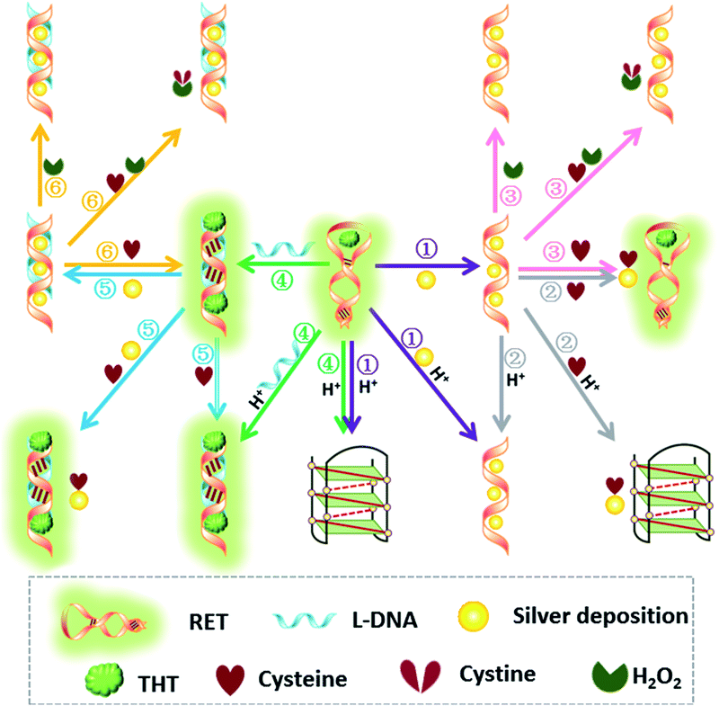
In order to design multi-level logic gates and further close the gap between DNA computation and electrical circuitries, herein we have constructed a label-free logic gate library focused on RET which is one type of proto-oncogene and encodes a receptor-type tyrosine kinase that has been implicated in the development of several human cancers, especially thyroid cancer.18 The logic gate library was implemented for the first time according to DNA hybridization and interaction between small molecules only without DNA replacement (Scheme 1). We proposed the construction of basic logic gates, single three-input, and the cascade of several chemical logic gates. Interestingly, a keypad-lock security system was designed by sequential logic operations. Moreover, a logic gate system for identification of even numbers and odd numbers from natural numbers was established successfully by employing four common and simple molecules. First of all, the developed logic gate is label-free realized with short oligonucleotides. Secondly, our methods may minimize or even eliminate complex analysis procedures that involve expensive instrumentation, and hold great promise for low-volume, and rapid readout of the analyte. Thirdly, a fluorescent signal as an output is considered to have a multitude of practical applications since the signal enables easy remote reading with low cost. Last but not the least, the developed system can also perform intelligent logic functions.
Results and discussion
Thioflavin T (ThT) consists of a pair of benzothiazole and dimethylaminobenzene rings freely rotating around a C–C bond which is a conjugated π bond between the two moieties.19 The fluorescence of ThT is quenched due to the internal rotation leading to a twist internal charge transfer (TICT). ThT requires an interaction with a “host” molecule in order to prevent the twisting which produces its fluorescence.20 For the RET sequence, a fitting cavity is available in a flexible hairpin structure at a neutral pH value.21 The interaction of the intercalated ThT with the cavities of the sequence is the stabilizing force for ThT binding, decreasing the TICT state, and increasing the fluorescence intensity (Fig. 1).22 Focusing on the fluorescence of ThT as the output and normalizing the obtained fluorescence signals by calculating a ratio, we converted this to Boolean logic levels by imposing a threshold of 0.54, thus constructing various logic gates as described next.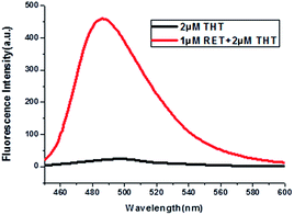 | ||
| Fig. 1 Fluorescence curves of ThT in aqueous solution (black curve) and ThT intercalated into RET in aqueous solution (red curve). | ||
Construction of basic logic gates
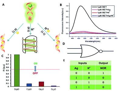
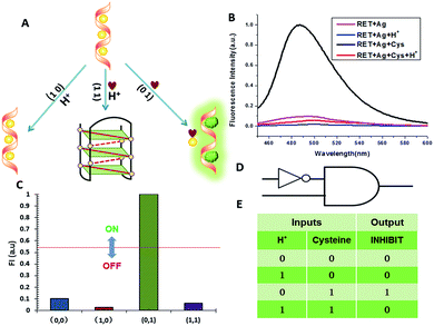
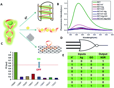
NOR and NAND gates are unique because they are functionally complete. That is, any computational operation can be implemented by layering either of these gates alone. Of these, the NOR gate is the simplest to implement using existing genetic parts.23 A NOR gate is “On” only when both inputs are “Off”.24 Based on the above results, we firstly designed a NOR logic gate that employed silver deposition and H+ as the inputs which were added to the solution of RET, and the fluorescence of ThT as the output (Fig. 2). With respect to the inputs, the presence and absence of silver deposition and H+ were defined as “1” and “0” respectively, with a threshold value of 0.54. Upon addition of H+, the RET sequence folded into an i-motif structure,22a which could not be inserted by ThT; consequently, the fluorescence of ThT turned off (output = 0). In addition, silver deposition on DNA scaffolds could effectively block the binding of the ThT to the RET sequence, and also likely worked as a fluorescence quencher; thus, the fluorescence was weak in the presence of both inputs. Furthermore, it is interesting to find that the logic system can be reset to its initial state by changing the buffer pH from 5.0 to 7.0 or by introducing cysteine with the molar ratio of cysteine/Ag = 2.0, which was a crucial property for practical applications of chemical logic gates. The fluorescence curves after resetting are shown in Fig. S1.†Moreover, inspired by the Ag–thiols interaction and the phenomenon that the chemisorbed thiols can bind much more strongly than DNA to the silver surface,25 an INHIBIT gate was performed based upon the silver deposited RET by employing H+ and cysteine as inputs. As shown in Fig. 3, a more dramatic fluorescence-on signal was obtained with cysteine (input: 0/1) than with other inputs (0/0, 1/0, 1/1). Thiols can remove the silver deposition from DNA scaffolds via the formation of Ag–S bonds. The “inactive” DNA originally stabilized or protected by silver deposition becomes “active”, and then ThT shows a dramatic increase in fluorescence as a result of the strong interaction between the intercalator (ThT) and the “activated” RET (output = 1). These results were in accordance with the proper execution of the Boolean INHIBIT logic gate which is represented by the situation where the output is “1” only if one particular input is “1” and the others are “0”. The gate can be easily reset by changing the buffer pH from 5.0 to 7.0 or through repeated silver deposition (Fig. S2†). Similarly, enlightened by the fact that H2O2 can oxidize cysteine to cystine,26 another INHIBIT gate was constructed based upon the silver deposited DNA system via introduction of the two inputs: cysteine and H2O2 (Fig. S3†). Only the addition of cysteine (input = 0/1) caused the fluorescence to increase greatly because the silver metalized RET could be readily released due to the etching interaction between thiols and silver. However, in the presence of both inputs, the oxidation of cysteine by H2O2 yields cysteine which cannot remove the silver deposition from the DNA scaffolds, resulting in fluorescence quenching.
In fact, every elementary logic gate, such as AND, OR, NOR, and INHIBIT, can be rewritten by combinations of IMPLICATION (IMP) and FALSE gates.11b Thus, IMP provides an outstanding attribute in Boolean logic. In this study, we constructed an IMP logic gate based upon the DNA/i-motif-mediated fluorescence changes.
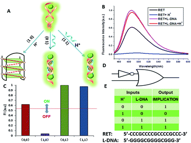
We defined H+ and L-DNA as the two inputs for our logic operation. RET can hybridize with L-DNA to form a DNA duplex with an extra four bases. The formation of DNA duplexes (input: 0/1) led to the significant fluorescence enhancement because ThT was almost non-fluorescent in aqueous solution but showed intense fluorescence upon interaction with the double-stranded DNA by intercalation (output = 1). When the RET solution was subjected to the two inputs together, there was competitive formation of double-stranded DNA (dsDNA) and the i-motif structure. As shown in Fig. 4, the strong fluorescence intensity indicated that the affinity of the double helix was much stronger than that of the i-motif. This input/output behavior yielded in an IMPLICATION logic gate: the Boolean function provides the output “1” in all circumstances, except for the case where one particular input is “1”. In addition, Exo III can catalyze the stepwise hydrolysis of mononucleotides from the blunt or recessed 3′-terminus of dsDNA. Its activity on single-stranded DNA (ssDNA) and the 3′-protruding end of dsDNA is limited.27 Therefore, this distinctive Exo III-catalyzed hydrolysis reaction is exploited to make the system feasible to reset. The fluorescence curves after resetting with different combinations of the inputs are presented in Fig. S4.† Meanwhile, another IMPLICATION gate was realized based on the fact that Graphene Oxide (GO) can differentiate between ssDNA and dsDNA due to their characteristic interactions with GO28 (Fig. S5†). When the RET solution was incubated with GO, due to the π–π stacking effect between ssDNA and the GO, RET was easily absorbed on the GO and the fluorescence of ThT was turned off (output = 0). After the formation of dsDNA, the dsDNA was removed from the GO owing to the weak affinity between GO and dsDNA and the fluorescence recovered (output = 1).
It is important to note that dsDNA can also form stable complexes with Ag(I) by inserting the ions inside the double helix, and silver nanowires on DNA scaffolds have been constructed through the reduction of silver-ion-laden λ-DNA.29 Similarly, thiols exhibit intriguing reactivity with the silver deposition. Therefore, the third IMPLICATION logic gate was achieved by taking dsDNA as the substrate and utilizing silver deposition and cysteine as the inputs (Fig. S6†). The last basic gate was realized based on the silver deposited DNA duplex by employing cysteine and H2O2 as inputs (Fig. S7†). The true output “1” was obtained only when cysteine was introduced and the input state was (1/0), whereas the other input states (0/0, 0/1, 1/1) generated the false output “0”.
Construction of a single, three-input NOR gate
A three-input majority gate is one of the most basic logic gates and has been demonstrated in many fields.30 With multiple inputs this gate can accept and produce a high volume of information; thus, on the molecular level a three-input majority gate can serve as a basic and versatile building block for constructing more complex circuits. For a single three-input NOR gate, it possess three inputs and produces an output of “1” only in the absence of any input. In this work we experimentally realized a three-input majority gate based on RET and demonstrated that it reliably produced all of the false outputs “0” with different combinations of the inputs. H+, silver deposition and GO were selected as the inputs respectively, with a threshold value of 0.54. As shown in Fig. 5, the truth table specifies that the three inputs have the same priority among one another. Only when the input state was (0/0/0), was the output “1”, whereas the other input states (1/0/0, 0/1/0, 1/1/0, 0/0/1, 1/0/1, 0/1/1, 1/1/1) displayed the output “0”. These results are in accordance with the proper execution of the NOR logic gate.Construction of cascaded logic gates
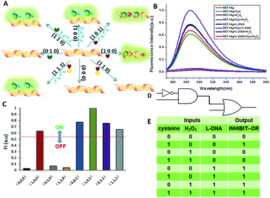
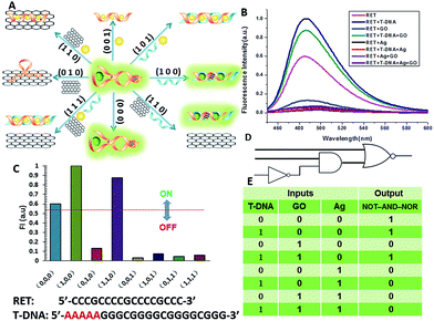
The aforementioned examples have shown that the logic library based on RET is composed of several types of logic operations based on two or three simple inputs. However, the major challenge in the logic systems is the possibility of assembling multicomponent/multifunctional logic circuitries. To demonstrate the system necessary for these multi-level integrated circuits, the versatility of the inputs is implemented to construct cascaded logic gates. In the following set of representative experiments, we expected that our logic system could be scaled up to perform large networking systems mimicking natural biochemical pathways. The first cascaded gate was constructed by combining an INHIBIT gate with an OR gate (Fig. 6). Based upon the silver deposited RET system, we chose cysteine, H2O2 and L-DNA as input 1, input 2 and input 3 respectively in the operation of the combinatorial gate. When the input states were (0/0/0, 0/1/0, 1/1/0), the output was “0”, whereas the other input states (1/0/0, 0/0/1, 1/0/1, 0/1/1, 1/1/1) displayed the output “1”. Furthermore, the logic system can be reset to its initial state by introducing Exo III or through repeated silver deposition (Fig. S8†). Another combinatorial NOT–AND–NOR gate was achieved by utilizing T-DNA, GO and silver deposition as the inputs and the RET solution as the basic system. As shown in Fig. 7, when the input states were (0/1/0, 0/0/1, 1/0/1, 0/1/1, 1/1/1), the output was “0”, whereas the other input states (0/0/0, 1/0/0, 1/1/0) displayed the output “1”.Construction of a superimposed molecular keypad-lock security system
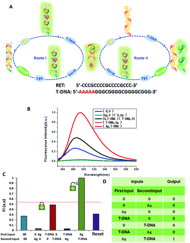
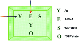
The logic functions described thus far are mainly combinatorial functions, where the state of the output is determined solely by the input combination, with no dependence on the order in which the inputs are applied. In sequential logic, the most important feature of the keypad-lock security system is the dependence of the output signal, not only upon the proper combination of the inputs but also upon the order in which these inputs are introduced. In other words, one needs to know the exact password that opens this lock. Fundamental logic gates are the basic building blocks for the construction of superior biocomputing security systems. Based on the above discussions, a superimposed molecular keypad-lock security system was constructed. A mixture of RET and ThT was used as an initial system which involved stepwise treatment with silver deposition and T-DNA defined as the input signals. In particular, T-DNA can hybridize with RET to form a DNA duplex with an extra five bases. The high and weak fluorescence values were considered as 1 (“On”) and 0 (“Off”), respectively, with a threshold value of 0.54. Fig. 8C shows a bar presentation of the output of the keypad-lock. Only the (Ag/T-DNA) input can trigger the system to adopt the “On” state.To visualize these sequence-dependent phenomena directly, the sequential logic operation with memory function can be constructed as a password entry. As illustrated in Fig. 9, the input of Ag was designated as the character “Y” and the input of T-DNA was designated as the character “E”. When the input “Y” was added first, emission as the character “S” (strong fluorescence, On) was observed as the result of memorizing the input sequence. The combination of inputs gave the password “YES” to open the keypad-lock. On inverting the addition sequence to T-DNA and Ag, an obvious fluorescence quenching (Off, designated as the character “O”) was observed. This input sequence gave the word “EYO”, which corresponded to the denial of unauthorized access and failure to open the keypad-lock. This demonstrated that one can use “YES” as a security code to open the keypad-lock. The use of numerical digits (0–9) as PIN numbers in a two-digit password allows a total of 90 different combinations. The choice becomes wider (650 different combinations) when individual letters (A–Z), each signifying a specific ionic input, are used as the PIN numbers. Thus, access codes could be made possible by assigning the correct starting (Ag) and ending (T-DNA) inputs to two specific letters (Y and E, respectively) and different inputs to all of the other letters, to ensure that only one code would work. But there are many combinations to try and this adds to the complexity of cracking the keypad-lock.
The developed keypad-lock can be facilely reset after operation, which is critical for multiple operations of the keypad-lock. Otherwise, the function could be performed only once which would limit the effectiveness of such a strategy. If the correct password is input, the lock will be opened and cannot be closed again. If one inputs the wrong password, the lock will never be opened. In contrast to previous studies, this RET-based system could be regenerated. Here, by taking advantage of the attractive properties of the Ag–thiols interaction and Exo III, the designed keypad system can be facilely reset from the “On” or the “Off” state without a laborious process. As shown in Fig. 8A, the DNA duplexes have a blunt 3′-terminus and a five-base adenine tail. Since Exo III can only catalyze the hydrolysis of mononucleotides from the blunt 3′-terminus of dsDNA, the addition of Exo III would start the stepwise removal of mononucleotides from the blunt 3′-terminus of T-DNA, with RET remaining intact. Followed by the hydrolysis process, the solution is heated for 5 min to inhibit the activity of Exo III so as to eliminate the interference from Exo III. Fig. 10 shows that after resetting the system, the On or Off state could be reached again when the system was triggered by different input sequences. This demonstrates that the logic operation reported here can be used for the next cycle, which is a crucial property for the practical application of keypad-locks.
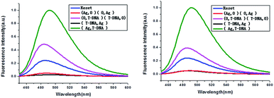 | ||
| Fig. 10 Fluorescence curves of the system after resetting with different combinations of the inputs for the keypad-lock. | ||
Construction of the parity checker
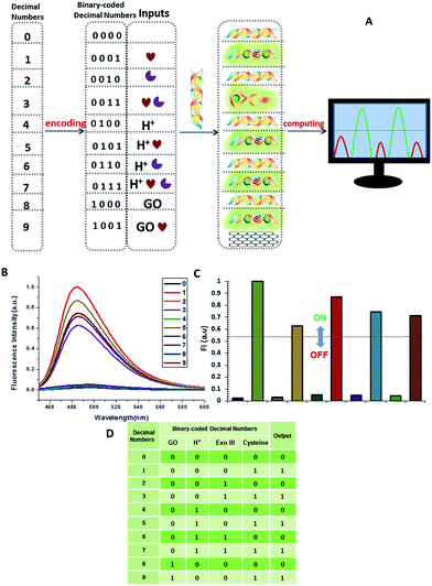
A multifunctional molecular platform should be capable of performing a multitude of logic operations. One of these is the function of a parity checker, an essential device for the detection of erroneous procedures in data transmission.31 To demonstrate the application prospects of the RET-regulated logic platform, we have applied this circuit with a slight modification to identify even numbers and odd numbers from natural numbers less than 10. Firstly, these decimal numbers were encoded with a binary-coded decimal (BCD) code.32 Each decimal digit was transformed into a four-bit binary number, then GO, H+, Exo III and cysteine were chosen to be assigned to the four bits as the inputs, respectively, and the silver deposited dsDNA was used as the initial state. When the input state is (0/0/0/1), the silver metalized dsDNA could be readily released owing to the specific thiols–Ag interaction (output = 1). Exo III can catalyze the stepwise hydrolysis of dsDNA to form ssDNA, and hence the (0/0/1/1) state presents a true output. Remarkably, when the inputs involved H+, Exo III and cysteine, H+ inactivated Exo III and the input state (0/1/1/1) also presented a true output. According to the experimental results, H+ and GO had little influence on the dsDNA, but a large influence on ssDNA. As we had expected, the input states (0/1/0/1, 1/0/0/1) resulted in true outputs and the input state (0/1/0/0) resulted in a false output. The other input states involving silver deposition all presented false outputs. The computational results of the four-input binary logic gate system are shown in Fig. 11. The checker gave an alert in the form of a binary “1” for the output if it received an odd number. As expected, the corresponding fluorescence intensity of all the odd numbers produced a true output, whereas the even numbers presented a false output. The checker gave a binary output “0” for all the even numbers. These results demonstrate that the parity checker is capable of identification of all the even numbers and odd numbers because the parity of a natural number is determined by the digit in the unit position, no matter how large the number is.Perspectives for medical applications
Moreover, our molecular logics could potentially be applied to medical diagnostics. For example, in the previously described INHIBIT gates which employed silver deposited DNA for the initial state, cysteine and H2O2 perform the simple logic operation. Cysteine plays a vital role in reversible redox reactions inside cells, which have numerous biological functions in metabolism and detoxification. It is also recognized to be a potential neurotoxin and serves as a biomarker in various medical diagnoses. For instance, cysteine at a deficient level is associated with slowed growth, hair depigmentation, edema, liver damage, skin lesions, and weakness.33 A facile analysis of cysteine levels is therefore pivotal to the early diagnosis of these diseases. Silver nanoclusters (AgNCs) have recently been used to construct optical sensors for cysteine due to their good biocompatibility and photostability.34 When AgNCs were exposed to the targeted cysteine, the turn-off changes in the fluorescence intensity of the assay solution provided superior selectivity for cysteine owing to the specific thiols–Ag interaction. Similarly, our silver deposited DNA has the potential to respond to cysteine inside cells. What is more, by employing ThT as a fluorescence indicator, it is expected that a binding-induced fluorescence turn-on assay can be performed instead of turn-off changes which are often suspected to give false positive results. The addition of H2O2, another input of the INHIBIT gates, is further proof for cysteine analysis. These demonstrate the feasibility of performing medical diagnostics using a logic gate design. Further work in our group along this line is expected to realize the idea.Conclusion
In conclusion, we have successfully established a versatile, alternate, large-scale logic library based on DNA hybridization and reaction between small molecules only, with a final fluorescent signal output for logic performance and detection. In this logic gate library, the output of the previous gate was used as the input of the next logic gate. By means of this concatenation, all the basic logic gates were connected to communicate with each other. In addition, we demonstrated that a library of simple gates can be used to form more complex computational operations by linking the gates using diffusible chemical signals. Our multi-level logic gates (INHIBIT–OR, NOT–AND–NOR) showed a high switching ratio between the output signals “1” and “0”, which makes it possible to distinguish different health states and simultaneously facilitates fast and accurate diagnosis. Subsequently, a biocomputing keypad-lock security system was designed using sequential logic operations. Moreover, a parity checker which can identify even numbers and odd numbers from natural numbers was successfully established. The distinct advantage of this system is that it is label-free, which makes it simple to operate. Importantly, these logic gates were carried out in aqueous media, potentiating their application in biological and biomedical systems. Due to the low-cost, well-ordered and predictable structure of our system, our sensor may serve as a promising proof of principle that demonstrates increased computational complexity and enhanced sensor performance by linking multiple logic gates together. Further work along these lines is expected to produce such information-processing and smart therapeutic agents.Experimental details
Chemicals and materials
DNA sequences used in this work are listed as follows:RET: 5′-CCCGCCCCGCCCCGCCC-3′;
L-DNA: 5′-GGGGCGGGGCGGG-3′;
T-DNA: 5′-AAAAAGGGCGGGGCGGGGCGGG-3′.
All of the synthesized oligonucleotides were purchased from Shanghai Sangon Biotechnology Co. Ltd. (Shanghai, China). Silver nitrate (AgNO3) and sodium borohydride (NaBH4) were purchased from Aladdin Ltd. (Shanghai, China). Thioflavin T (ThT) and L-cysteine were obtained from Sigma-Aldrich. Hydrogen peroxide solution (30%) was purchased from Sinopharm Chemical Reagent Co. Ltd. (Shanghai, China). Tris–Ac buffer (10 mM, pH = 8) was used to control the acidity of the reaction solution. All chemicals used in this work were of analytical reagent grade and were obtained from commercial sources and used directly without additional purification.
Synthesis of silver deposition on ssDNA scaffolds
The ssDNA-templated silver deposition was carried out by the reduction of AgNO3 with NaBH4 in the presence of DNA. Briefly, RET (1.0 × 10⁻⁴ M, 4 μL) was mixed with an excess of AgNO3 (1.2 × 10⁻² M, 4 μL) (120![[thin space (1/6-em)]](https://www.rsc.org/images/entities/char_2009.gif) :
:![[thin space (1/6-em)]](https://www.rsc.org/images/entities/char_2009.gif) 1 AgNO3/DNA molar ratio) in 200 μL buffer (10 mM Tris-Ac, pH = 8). After incubation for 5 min, freshly prepared NaBH4 (3 × 10⁻² M, 8 μL) at a 1
1 AgNO3/DNA molar ratio) in 200 μL buffer (10 mM Tris-Ac, pH = 8). After incubation for 5 min, freshly prepared NaBH4 (3 × 10⁻² M, 8 μL) at a 1![[thin space (1/6-em)]](https://www.rsc.org/images/entities/char_2009.gif) :
:![[thin space (1/6-em)]](https://www.rsc.org/images/entities/char_2009.gif) 5 molar ratio of [AgNO3]/[NaBH4] was added dropwise into the above aqueous solution under vigorous stirring. After mixing, the resulting yellow colloidal silver solution was stirred for another 40 min.
5 molar ratio of [AgNO3]/[NaBH4] was added dropwise into the above aqueous solution under vigorous stirring. After mixing, the resulting yellow colloidal silver solution was stirred for another 40 min.
Synthesis of silver deposition on dsDNA scaffolds
The method for synthesis of silver deposition on dsDNA scaffolds is similar to silver deposition on ssDNA. Briefly, RET (1.0 × 10⁻⁴ M, 4 μL) was first hybridized with its complementary oligonucleotide strand L-DNA/T-DNA at the same concentration (1.0 × 10⁻⁴ M, 4 μL) in 200 μL buffer (10 mM Tris-Ac, pH = 8) for 30 min. Next, an excess of AgNO3 (1.2 × 10⁻² M, 6 μL) at a 120![[thin space (1/6-em)]](https://www.rsc.org/images/entities/char_2009.gif) :
:![[thin space (1/6-em)]](https://www.rsc.org/images/entities/char_2009.gif) 1 ratio of [AgNO3]/[DNA] was added to the DNA duplex solutions. After incubation for 5 min, freshly prepared NaBH4 (3 × 10⁻² M, 12 μL) at a 1
1 ratio of [AgNO3]/[DNA] was added to the DNA duplex solutions. After incubation for 5 min, freshly prepared NaBH4 (3 × 10⁻² M, 12 μL) at a 1![[thin space (1/6-em)]](https://www.rsc.org/images/entities/char_2009.gif) :
:![[thin space (1/6-em)]](https://www.rsc.org/images/entities/char_2009.gif) 5 molar ratio of [AgNO3]/[NaBH4] was added dropwise into the above aqueous solution under vigorous stirring. After mixing, the resulting yellow colloidal silver solution was stirred for another 40 min.
5 molar ratio of [AgNO3]/[NaBH4] was added dropwise into the above aqueous solution under vigorous stirring. After mixing, the resulting yellow colloidal silver solution was stirred for another 40 min.
The fluorescence assay
Cysteine: firstly, the above silver-coated ssDNA/dsDNA was mixed with cysteine (1 × 10⁻³ M, 50 μL). After the mixture had equilibrated for 1 h at room temperature, ThT (100 μM, 20 μL) was added and equilibrated for 1 min before spectral measurements.H2O2: cysteine was firstly treated with H2O2 (120![[thin space (1/6-em)]](https://www.rsc.org/images/entities/char_2009.gif) :
:![[thin space (1/6-em)]](https://www.rsc.org/images/entities/char_2009.gif) 1 cysteine/H2O2 molar ratio) for 30 min in 10 mM Tris–Ac buffer (pH = 8.0), and the resulting solution was then transferred to the silver-coated DNA system. ThT (100 μM, 20 μL) was added and equilibrated for 1 min before spectral measurements were taken.
1 cysteine/H2O2 molar ratio) for 30 min in 10 mM Tris–Ac buffer (pH = 8.0), and the resulting solution was then transferred to the silver-coated DNA system. ThT (100 μM, 20 μL) was added and equilibrated for 1 min before spectral measurements were taken.
The i-motif: RET (10 μM) was diluted in 970 μL buffer (10 mM Tris–Ac, pH = 5). After incubation for 5 min, ThT (100 μM, 20 μL) was added and equilibrated for 1 min before spectral measurements were taken.
After that, a 0.1 mL aliquot of the mixture was excited at 425 nm, and the fluorescence intensity was collected from 445 to 600 nm.
Acknowledgements
This work was financially supported by the National Science of Foundation of China (81171646, 31170776 and 21472139), the Science and Technology Commission of Shanghai Municipality (14DZ2261100) as well as the Fundamental Research Funds for the Central Universities.References
- M. Zhou, N. Zhou, F. Kuralay, J. R. Windmiller, S. Parkhomovsky, G. Valdés-Ramírez, E. Katz and J. Wang, Angew. Chem., Int. Ed., 2012, 51, 2686–2689 CrossRef CAS PubMed
.
- M. You, L. Peng, N. Shao, L. Zhang, L. Qiu, C. Cui and W. Tan, J. Am. Chem. Soc., 2014, 136, 1256–1259 CrossRef CAS PubMed
.
- Y. Benenson, B. Gil, U. Ben-Dor, R. Adar and E. Shapiro, Nature, 2004, 429, 423–429 CrossRef CAS PubMed
.
- E. Shapiro and Y. Benenson, Sci. Am. Rep., 2007, 17, 40–47 CrossRef
.
- P. A. de Silva, N. H. Gunaratne and C. P. McCoy, Nature, 1993, 364, 42–44 CrossRef
.
-
(a) J. Elbaz, F. Wang, F. Remacle and I. Willner, Nano Lett., 2012, 12, 6049–6054 CrossRef CAS PubMed
; (b) T. Li, E. Wang and S. Dong, J. Am. Chem. Soc., 2009, 131, 15082–15083 CrossRef CAS PubMed
; (c) M. N. Stojanovic, T. E. Mitchell and D. Stefanovic, J. Am. Chem. Soc., 2002, 124, 3555–3561 CrossRef CAS PubMed
; (d) F. Wang, X. Liu and I. Willner, Angew. Chem., Int. Ed., 2015, 54, 1098–1129 CrossRef CAS PubMed
; (e) R. Orbach, B. Willner and I. Willner, Chem. Commun., 2015, 51, 4144–4160 RSC
.
-
(a) R. Guliyev, S. Ozturk, Z. Kostereli and E. U. Akkaya, Angew. Chem., 2011, 123, 10000–10005 CrossRef
; (b) T. Gupta and M. E. van der Boom, Angew. Chem., 2008, 120, 2292–2294 CrossRef
; (c) T. Gupta and M. E. van der Boom, Angew. Chem., 2008, 120, 5402–5406 CrossRef
; (d) S. Silvi, E. C. Constable, C. E. Housecroft, J. E. Beves, E. L. Dunphy, M. Tomasulo, F. M. Raymo and A. Credi, Chem.–Eur. J., 2009, 15, 178–185 CrossRef CAS PubMed
; (e) J. Elbaz, O. Lioubashevski, F. Wang, F. Remacle, R. D. Levine and I. Willner, Nat. Nanotechnol., 2010, 5, 417–422 CrossRef CAS PubMed
.
-
(a) S. Erbas-Cakmak, O. Altan Bozdemir, Y. Cakmak and E. U. Akkaya, Chem. Sci., 2013, 4, 858–862 RSC
; (b) M. Amelia, M. Baroncini and A. Credi, Angew. Chem., 2008, 120, 6336–6339 CrossRef
; (c) J. Andréasson, S. D. Straight, S. Bandyopadhyay, R. H. Mitchell, T. A. Moore, A. L. Moore and D. Gust, Angew. Chem., Int. Ed., 2007, 46, 958–961 CrossRef PubMed
; (d) E. Perez-Inestrosa, J.-M. Montenegro, D. Collado and R. Suau, Chem. Commun., 2008, 1085–1087 RSC
.
-
(a) B.-B. Cui, Y.-W. Zhong and J. Yao, J. Am. Chem. Soc., 2015, 137, 4058–4061 CrossRef CAS PubMed
; (b) P. Remón, M. Bälter, S. Li, J. Andréasson and U. Pischel, J. Am. Chem. Soc., 2011, 133, 20742–20745 CrossRef PubMed
.
-
(a) J. Andréasson, S. D. Straight, T. A. Moore, A. L. Moore and D. Gust, J. Am. Chem. Soc., 2008, 130, 11122–11128 CrossRef PubMed
; (b) P. Ceroni, G. Bergamini and V. Balzani, Angew. Chem., 2009, 121, 8668–8670 CrossRef
; (c) Y. He, Y. Chen, C. Li and H. Cui, Chem. Commun., 2014, 50, 7994–7997 RSC
.
-
(a) O. A. Bozdemir, R. Guliyev, O. Buyukcakir, S. Selcuk, S. Kolemen, G. Gulseren, T. Nalbantoglu, H. Boyaci and E. U. Akkaya, J. Am. Chem. Soc., 2010, 132, 8029–8036 CrossRef CAS PubMed
; (b) M. Elstner, J. Axthelm and A. Schiller, Angew. Chem., Int. Ed., 2014, 53, 7339–7343 CrossRef CAS PubMed
.
-
(a) J. Zhu, X. Yang, L. Zhang, L. Zhang, B. Lou, S. Dong and E. Wang, Chem. Commun., 2013, 49, 5459–5461 RSC
; (b) Z. Zhou, Y. Liu and S. Dong, Chem. Commun., 2013, 49, 3107–3109 RSC
; (c) C. P. Carvalho, Z. Domínguez, J. P. Da Silva and U. Pischel, Chem. Commun., 2015, 51, 2698–2701 RSC
.
-
(a) M. N. Stojanovic, Prog. Nucleic Acid Res. Mol. Biol., 2008, 82, 199–217 CAS
; (b) J. Macdonald, D. Stefanovic and M. N. Stojanovic, Sci. Am., 2008, 299, 84–91 CrossRef CAS PubMed
; (c) J. Macdonald, Y. Li, M. Sutovic, H. Lederman, K. Pendri, W. Lu, B. L. Andrews, D. Stefanovic and M. N. Stojanovic, Nano Lett., 2006, 6, 2598–2603 CrossRef CAS PubMed
.
-
(a) M. N. Stojanovic and D. Stefanovic, Nat. Biotechnol., 2003, 21, 1069–1074 CrossRef CAS PubMed
; (b) E. Katz and S. Minko, Chem. Commun., 2015, 51, 3493–3500 RSC
; (c) E. Katz and V. Privman, Chem. Soc. Rev., 2010, 39, 1835–1857 RSC
.
-
(a) B. M. Frezza, S. L. Cockroft and M. R. Ghadiri, J. Am. Chem. Soc., 2007, 129, 14875–14879 CrossRef CAS PubMed
; (b) R. Orbach, S. Lilienthal, M. Klein, R. D. Levine and I. Willner, Chem. Sci., 2015, 6, 1288–1292 RSC
.
-
(a) L. Qian and E. Winfree, Science, 2011, 332, 1196–1201 CrossRef CAS PubMed
; (b) L. Qian, E. Winfree and J. Bruck, Nature, 2011, 475, 368–372 CrossRef CAS PubMed
.
- D. L. Ma, H. Z. He, V. Y. Ma, D. H. Chan, K. H. Leung, H. J. Zhong, L. Lu, J. L. Mergny and C. H. Leung, Anal. Chim. Acta, 2012, 733, 78–83 CrossRef CAS PubMed
.
-
(a) K. Guo, A. Pourpak, K. Beetz-Rogers, V. Gokhale, D. Sun and L. H. Hurley, J. Am. Chem. Soc., 2007, 129, 10220–10228 CrossRef CAS PubMed
; (b) J. Zhou, C.-Y. Wei, G.-Q. Jia, X.-L. Wang, Z.-C. Feng and L. Can, Mol. BioSyst., 2010, 6, 580–586 RSC
.
- V. Babenko and W. Dzwolak, Chem. Commun., 2011, 47, 10686–10688 RSC
.
- R. Ghosh and D. K. Palit, ChemPhysChem, 2014, 15, 4126–4131 CrossRef CAS PubMed
.
- I. J. Lee, S. P. Patil, K. Fhayli, S. Alsaiari and N. M. Khashab, Chem. Commun., 2015, 51, 3747–3749 RSC
.
-
(a) V. I. Stsiapura, A. A. Maskevich, S. A. Tikhomirov and O. V. Buganov, J. Phys. Chem. A, 2010, 114, 8345–8350 CrossRef CAS PubMed
; (b) P. K. Singh, M. Kumbhakar, H. Pal and S. Nath, Phys. Chem. Chem. Phys., 2011, 13, 8008–8014 RSC
.
- T. W. Scharle, Notre Dame Journal of Formal Logic, 1965, 6, 209–217 CrossRef
.
- A. Tamsir, J. J. Tabor and C. A. Voigt, Nature, 2011, 469, 212–215 CrossRef CAS PubMed
.
- Z. Chen, Y. Lin, C. Zhao, J. Ren and X. Qu, Chem. Commun., 2012, 48, 11428–11430 RSC
.
- F. Wang, X. Liu, C. H. Lu and I. Willner, ACS Nano, 2013, 7, 7278–7286 CrossRef CAS PubMed
.
- G. Strack, M. Ornatska, M. Pita and E. Katz, J. Am. Chem. Soc., 2008, 130, 4234–4235 CrossRef CAS PubMed
.
- H. Jang, Y. K. Kim, H. M. Kwon, W. S. Yeo, D. E. Kim and D. H. Min, Angew. Chem., 2010, 122, 5839–5843 CrossRef
.
-
(a) E. Braun, Y. Eichen, U. Sivan and G. Ben-Yoseph, Nature, 1998, 391, 775–778 CrossRef CAS PubMed
; (b) L. Berti, A. Alessandrini and P. Facci, J. Am. Chem. Soc., 2005, 127, 11216–11217 CrossRef CAS PubMed
.
-
(a) A. Imre, G. Csaba, L. Ji, A. Orlov, G. Bernstein and W. Porod, Science, 2006, 311, 205–208 CrossRef CAS PubMed
; (b) W. Tang, S.-C. Hu, H.-M. Wang, Y. Zhao, N. Li and F. Liu, Chem. Commun., 2014, 50, 14352–14355 RSC
; (c) W. Li, Y. Yang, H. Yan and Y. Liu, Nano Lett., 2013, 13, 2980–2988 CrossRef CAS PubMed
.
- M. Pärs, C. C. Hofmann, K. Willinger, P. Bauer, M. Thelakkat and J. Köhler, Angew. Chem., Int. Ed., 2011, 50, 11405–11408 CrossRef PubMed
.
- A. Timoshenko, S. Rastogi and P. Lala, Br. J. Cancer, 2007, 97, 1090–1098 CrossRef CAS PubMed
.
-
(a) S. Shahrokhian, Anal. Chem., 2001, 73, 5972 CrossRef CAS PubMed
; (b) H. S. Jung, J. H. Han, T. Pradhan, S. Kim, S. W. Lee, J. L. Sessler, T. W. Kim, C. Kang and J. S. Kim, Biomaterials, 2012, 33, 945 CrossRef CAS PubMed
.
-
(a) X. Yuan, Y. Tay, X. Dou, Z. Luo, D. T. Leong and J. Xie, Anal. Chem., 2013, 85, 1913–1919 CrossRef CAS PubMed
; (b) Z. Chen, D. Lu, Z. Cai, C. Dong and S. Shang, Luminescence, 2014, 29, 722–727 CrossRef CAS PubMed
.
Footnote |
| † Electronic supplementary information (ESI) available. See DOI: 10.1039/c5sc03570h |
| This journal is © The Royal Society of Chemistry 2016 |

