
Cellulose nanofiber-assisted dispersion of cellulose nanocrystals@polyaniline in water and its conductive films†
Shiqi Wangc,
Chun Wei*abc,
Yongyang Gongabc,
Jian Lvabc,
Chuanbai Yuabc and
Jinhong Yu*ad
aMinistry-Province Jointly-Constructed Cultivation Base for State Key Laboratory of Processing for Non-ferrous Metal and Featured Materials, Guangxi Zhuang Autonomous Region, China
bKey Laboratory of New Processing Technology for Nonferrous Metals and Materials, Ministry of Education, China
cCollege of Materials Science and Engineering, Guilin University of Technology, Guilin 541004, P. R. China
dKey Laboratory of Marine Materials and Related Technologies, Zhejiang Key Laboratory of Marine Materials and Protective Technologies, Ningbo Institute of Materials Technology and Engineering, Chinese Academy of Sciences, Ningbo 315201, China. E-mail: 1986024@glut.edu.cn; yujinhong@nimte.ac.cn
First published on 19th January 2016
Abstract
Dispersion is crucial for many applications of nanostructured materials. In this work, a facile and efficient method for dispersion of cellulose nanocrystals@polyaniline (CNCs@PANI) nanocomposites in an aqueous solution is reported by using cellulose nanofibers (CNFs) as a dispersant. CNCs@PANI was prepared for the experiment by using CNCs as a template and controlling the reactions to obtain fiber-like nanocomposites. Then, the nanocomposite was dispersed in water with the CNFs by means of mechanical shearing. The centrifugal and storage stabilities of the nanocomposite were measured, as well as the zeta potential. The results showed that the CNFs had special dispersion assisting effects for dedoped CNCs@PANI. The CNCs@PANI dispersion showed good centrifugal and storage stability, and a zeta potential of −30.7 mV was recorded with the addition of 10 wt% CNFs. This CNCs@PANI dispersion was cast to obtain a conductive film, which had tensile strength and electrical conductivity of 26.7 MPa and 104.7 S m−1, respectively.
1. Introduction
Recently, polyaniline (PANI) has received a high amount of attention from the nanoscience and nanotechnology fields. This is because PANI exhibits superior chemical sensing capabilities, a unique photothermal effect, thermoelectric effect and stem cell differentiation promoting effect, catalytic activity, and high electrochemical performance.1–8 However, PANI nanomaterials tend to aggregate and precipitate in water. Additionally, the application of PANI nanomaterials has been restricted by its poor ability to be processed and relatively poor mechanical properties. Therefore, finding a facile, efficient, and controlled method to disperse PANI nanomaterials is a highly desirable undertaking. Currently, there are a number of studies that have focused on the dispersion of PANI nanomaterials. Methods for dispersing PANI nanomaterials have included controlling the reaction, controlling the pH of dispersion,1 doping it with phosphate ester,9,10 adding ionic liquid based polymer electrolytes,11 and adding poly(sodium 4-styrenesulfonate).12 Li1 and co-author found in their research that PANI nanofibers are stable in water when the pH balance is controlled without the need for any chemical modification or steric stabilizers. The optimal pH level for stabilizing the colloid was found to be around 2.6. The formation of electrostatic repulsive forces between nanofibers through acid doping enabled the long-term stability of the colloids. This dispersion, however, is considered unstable when the pH is over 7 or lower than 1.5. In another study, Zhang9 and co-worker began preparation of aqueous conducting polyaniline nanofibers by using acidic phosphate ester, which contained hydrophilic ethylene glycol segment as a dopant.Cellulose and its derivatives have been use to stabilize PANI.13 Meanwhile carbon nanotubes (CNT)14–18 and graphene19,20 were also used to be stabilizer due to their special assisted dispersion effect. Shi et al.13 used cellulose to assist the solute and stabilize PANI in NaOH/urea solution, which resulted in excellent mechanical properties and conductive PANI-based films. They discovered that in the mixture solution, water-soluble cellulose inclusion complexes were entangled with PANI through hydrogen bonds between the –NH and –OH groups. This formed supramolecular structure, which led to the dissolution of PANI in the aqueous solution. Nobutsugu Minami et al.16 found sodium carboxymethyl cellulose to be an excellent dispersant for single-wall carbon nanotubes (SWCNT). Later, Christophe Olivier15 and his colleagues achieved preparation of luminescent SWCNT films by using a layering assembly method with water as the base. When this method was conducted in water by the cellulose nanocrystals (CNCs), it was found to assist in dispersion. They hypothesized that the reason for this is that the graphitic surface of the SWCNT is hydrophobic, and interactions between the SWCNT surface and the hydrophobic surface of CNCs are likely to occur during assisted dispersion of SWCNT. Mahiar M. Hamedi et al.14 are credited with discovering similar assisted dispersion effects during their studies. They used CNFs to obtain high-quality dispersions of SWCNT in water. They were also able to prepare high strength, conductive fibers.
The goal of this paper is to investigate the possible use of cellulose nanofibers (CNFs) as dispersants to disperse and stabilize cellulose nanocrystals@polyaniline (CNCs@PANI), which will result in the preparation of high strength and conductive films. It is potential applied to conductive ink, sensors, flexible supercapacitor, biomedicine, etc.
2. Experimental
2.1. Materials
Sisal pulp was prepared using the kraft pulping method. Analytical grade sulfuric acid, hydrochloric acid, aniline, ammonium persulfate, sodium hydroxide, sodium chloroacetate and polyvinyl alcohol (PVA-124) were purchased from the Xilong Chemical Co., Ltd. (China) and used without further purification. The high-speed mixer (JK-818II, 2200W) used during the experiment was purchased from Guangdong Zhenju Electrical Appliance Co., Ltd. (China).2.2. Preparation of CNCs
The dried sisal pulp (20.0 g) was dispersed into a 160 ml sulfuric acid solution (60 wt%) and subsequently placed in an ice water bath for 30 min. Then, this suspension was kept at 50 °C for 1 h to allow sisal pulp hydrolysis. The suspension was subsequently diluted with 160 ml deionized water and filtered to remove a large portion of the free acid. 750 ml of deionized water was then added to form a suspension. The concoction was neutralized with a sodium hydroxide solution. After high speed stirring and shearing with a high-speed mixer (JK-818) for 4 min, a translucent dispersion was formed. Then, the mix was placed in a centrifuge at 12![[thin space (1/6-em)]](https://www.rsc.org/images/entities/char_2009.gif) 000 rpm for 8 min to obtain dispersed CNCs. The dispersions were then placed into a plastic bottle and stored in a freezer until they were completely frozen. Afterwards, they were completely thawed at room temperature, filtered, and washed with deionized water to remove free ions. The CNCs suspension (4.18 wt%) was obtained after high speed stirring and shearing with a high-speed mixer for 2 min.
000 rpm for 8 min to obtain dispersed CNCs. The dispersions were then placed into a plastic bottle and stored in a freezer until they were completely frozen. Afterwards, they were completely thawed at room temperature, filtered, and washed with deionized water to remove free ions. The CNCs suspension (4.18 wt%) was obtained after high speed stirring and shearing with a high-speed mixer for 2 min.
2.3. Preparation of CNFs
24.0 g of dried sisal pulp was soaked in 72 ml of 7.7 wt% sodium hydroxide aqueous solution at room temperature for 30 min. Then, 480 ml of anhydrous ethanol and 7.4 g of sodium chloroacetate were added to the reaction, which was then kept at 71 °C for 4 h. Then, the mixture was filtered and washed with deionized water to remove free reagents from the dispersion. Deionized water was then added to form a suspension with 0.6–1 wt%. The suspension was then placed in a high speed mixer where it underwent stirring and shearing for 10 min, after which a transparent gel-like dispersion was formed. Finally, the dispersion was placed in a centrifuge as 12000 rpm for 8 min, resulting in a CNFs suspension (0.1 wt%). The obtained CNFs with –COOH group were sodium salt form CNF–COO−Na+ and used in this paper.
2.4. Preparation of CNC@PANI nanocomposites
In this experiment, 15.3 g CNCs (4.18 wt%) was added to 100 ml of deionized water and vigorously stirred to form a light-blue suspension. Then, 1.55 ml of aniline and 93 ml of HCl solution (1.3 M) were added. The mixture was then stirred and cooled to 5 °C. Afterwards, 30 ml of an ammonium persulfate solution (containing 0.38 g APS) was gradually added to the liquid over a time frame of 6 h. The resulting product was filtered and washed with distilled water to remove any by-products and remaining reagents. This process was followed by a thorough washing with 1 M NaOH and distilled water to dedope the CNC@PANI nanocomposites and denoted as C@P-1. The molar mass of the aniline and APS were simultaneously increased to secure CNC@PANI nanocomposites and denoted as C@P-X.2.5. Preparation of CNC@PANI/CNF nanocomposites and films
During a traditional preparation of CNC@PANI/CNF nanocomposites, the CNC@PANI (10.4 wt%) and CNF (0.6 wt%) are mixed with 200 ml water, then stirred by a high-speed mixer for 5 min to obtain a uniform dispersion. In this experiment, the obtained nanocomposites were secured in a centrifuge at 12000 rpm for 5 min. At the preparation of the conductive films, 10 wt% PVA was added to improve the film performance, and CNC@PANI/CNF/PVA composites were marked with their mass ratio of CNC@PANI over CNF as 9/81, 27/63, 45/45 and 81/9, respectively. Thin films were prepared by casting the CNC@PANI/CNF/PVA dispersions onto glass substrates, which resulted in homogeneous films after they were allowed to dry at 50 °C for 6 h. Then, the subjects were doped with HCl (1 M) and allowed to dry at room temperature in order to obtain conductive films. CNF/PVA (10 wt% PVA content) films were prepared at the same conditions for the purpose of comparison. A work-flow chart showing the interaction between CNF and CNC@PANI is shown in Fig. 1. The digital photograph of raw materials and product is displayed in Fig. S1.†
 | ||
| Fig. 1 Scheme of interaction between CNF and CNC@PANI. | ||
2.6. Characterization
Fourier transform infrared spectra (FT-IR) was recorded using Nicolet 470 spectrophotometer at a resolution of 4 cm−1 over the range of 4000–500 cm−1, and all samples were carried out after strict drying. Transmission electron microscopy (TEM) was recorded using a JEOL JEM-2100F microscope operating at 200 kV. Drops of ca. 0.001 wt% CNCs and CNFs suspensions were deposited onto glow-discharged carbon-coated transmission electron microscopy grids. These were negatively stained with 2 wt% uranyl acetate. The length and width of the CNCs were measured using the images generated by the nano measurer software. Atomic force microscopy (AFM) observations were performed using an NT-MDT Ntegra Prima SPM instrument. Small drops of ca. 0.001 wt% CNC suspensions were deposited onto fresh mica flakes. They were then rapidly vacuum-dried at 50 °C. Topography images were taken and recorded in the tapping mode. The zeta potential of the suspensions were measured used a Malvern Zetasizer Nano ZS90 instrument with solid content of 0.5 mg ml−1 at 25 °C and pH = 7.0. The refractive index of the CNC@PANI and CNFs were set as 1.51 and 1.48, respectively. Three different measurements were made during the process. These measurements were averaged in order to find the most reliable results possible.The four probe method was applied to measure the electro-conductivity of CNC@PANI films. The samples were prepared using an infrared testing pelletizer at 12 MPa. The electro-conductivity of the composite films was measured using the two-probe method on a model 4200 multimeter/switch system (Keithley), a process that was slightly modified from previous research.21,22 The samples were cut into strips (5.93 mm width). The electro-conductivity was measured three separate times at different locations throughout the surface of the material. The electro-conductivity (S m−1) of the films was calculated according to eqn (1):21,22
| σ = 1/ρ = L/(Rdh) | (1) |
In the above equation, ρ is resistivity in ohm meters (Ω m), R is the measured resistance of a film (Ω), d is the width of film strips (m), h is the film thickness (m), and L is the distance between the two parallel electrodes (m). After conducting the measurements, the average of all six results was deemed the official report.
The dynamic mechanical analysis (DMA) was operated using the controlled force mode to obtain the static stress–strain curves (5 N min−1, 25 °C).23,24 The specimens were 20 × 5.93 × 0.01 mm. Five specimens were tested and studied.
3. Results and discussion
3.1. Properties and structure of CNCs and CNFs
The FTIR spectra of CNCs and CNFs are displayed in Fig. 2. For CNF–COO−Na+, a strong absorption peak at 1596 cm−1 was observed. This peak is likely due to the varying vibration of the –COO−Na+ group found among the CNF's. After the sample was acidified, the absorption peak at 1596 cm−1 disappeared and converted into 1726 cm−1 (see the FTIR spectra of CNF–COOH), which was attributed to the vibration of the –COOH. These results indicate that the sodium chloroacetate grafted onto the cellulose by Williamson ether synthesis. CNCs and CNFs presented characteristic absorption bands around 3345 and 2900 cm−1, which can be attributed to the O–H stretching and C–H stretching which is common in cellulose. | ||
| Fig. 2 FTIR spectra of CNC, CNF–COO−Na+ and CNF–COOH. | ||
A TEM study was conducted to review the morphology of CNCs and CNFs, as shown in Fig. 3. The images of CNCs and CNFs are shown in Fig. 3(a and b), respectively. The length (L) and thickness (D) were measured by analysing TEM images through the statistics of 200 fibers and showed in Fig. S2.† As seen in Fig. 3(a) and S2(a),† CNCs is generally rod-shaped, with a lengths range from 50 to 550 nm with a mean of 〈L〉 = 117.23 nm, and its diameters range from 4 to 17 nm with a mean of 〈D〉 = 9.51 nm. The aspect ratio defined as CNC length over diameter, L/D, is shown in Fig. S2(c),† with a mean of 〈L/D〉 = 18.1. The shape of the CNFs was shown to be similar to that of nanofiber, while its diameter was smaller than CNC with a mean of 〈D〉 = 6.43 nm. The inset picture of Fig. 3(a and b) shows that CNCs and CNFs have self-assembly and chiral nematic natures. This is due to their rod-like shape, which lends itself to spontaneous ordering and nematic phase transition.25 In order to truly understand the total diameter of CNCs and CNFs, AFM measurements were performed on all of our test subjects. These results can be found in Fig. 4. The results show that the diameters of CNCs and CNFs with a mean of 〈D〉 = 5.04 nm and 2.87 nm, respectively. This value was smaller than statistic from TEM images is due to the different characterization.
 | ||
| Fig. 3 TEM images of CNC (a) and CNF (b). The inset picture is the CNC and CNF dispersion in water (the concentration is 1.0 and 0.6 wt%, respectively) and taken through polarizing. | ||
 | ||
| Fig. 4 AFM images of (a) CNC and (d) CNF. (b) and (e) are height profiles corresponding to (a) and (d), respectively. Histograms of measured values for (c) CNC and (f) CNF diameter. | ||
3.2. Characterization of CNC@PANI nanowires
The concentrations of the reactants were tightly controlled in order dictate the rate of reaction and acquire high quality CNC@PANI nanowires. SEM images of CNC@PANI nanocomposites are displayed in Fig. 5. Fig. 5(a) schematically illustrates the typical PANI shell on the CNC. The SEM image of the CNC@PANI nanocomposites reveal that the PANI uniformly coated the CNCs when the concentration of aniline and ammonium persulfate was 0.07 mol L−1, and its diameter was about 65.4 ± 17.4 nm. As the levels of aniline and ammonium persulfate were further increased, PANI gathered together to form bulk PANI particles, as can be observed in Fig. 5(b–f). | ||
| Fig. 5 (a) The schematic view of CNC@PANI in (b). FESEM image of CNC@PANI nanocomposites with different concentration of aniline and APS: (b) 0.07, (c) 0.28, (d) 0.42, (e) 0.49, (f) 0.56 mol L−1. | ||
To study the formation mechanism of CNC@PANI, FTIR and UV-vis testing of CNC@PANI was performed. The results are shown in Fig. 6. In Fig. 6(a), the absorption peak of 2897 and 1056 cm−1 is attributed to the vibration of –CH– and C–O–C in CNC. In Fig. 6(b), it was found that the absorption peak of 3444, 3398 and 3233 cm−1 is attributed to the N–H stretching vibration of the –NH– and –NH2 group of the dedoped PANI. However, for CNC@PANI, the absorption peak shifted to 3334 and 3268 cm−1. This indicted the hydrogen bond interaction occurs between the PANI and the CNCs, and moves frequencies towards lower frequencies.13,26 The UV-vis spectra in Fig. 6(c) show that the dedoped PANI had two absorption peaks at 342 and 663 nm, which can be explained by the π–π* transition of the benzenoid rings and n–π* transition of the quinonoid rings, respectively.9,27 However, the π–π* and n–π* transition bands of CNC@PANI blue-shifted to 327 and 592 nm, respectively. This might be due to the interaction that arises from the hydrogen bonding between PANI and CNCs.26 This demonstrates that PANI polymerizes and self-assembles on CNCs through hydrogen bond interaction.
 | ||
| Fig. 6 FTIR spectra (a) and 3100–3600 cm−1 (b) in (a), UV-vis spectra (c) of dedoped PANI and CNC@PANI; (d) conductivity of CNC@PANI nanocomposites. | ||
As shown in Fig. 6(d), it is apparent that the conductivity of CNC@PANI nanocomposites is dependent on the concentration of aniline and ammonium persulfate in the compound. The conductivity of the CNC@PANI nanocomposites increased as the concentration of the reactants was increased. The maximum value of CNC@PANI nanocomposite observed during our tests was 166.7 S m−1, which was recorded by C@P-7.
3.3. The assisted dispersion effect of cellulose nanofiber
To understand the assisted dispersion effects pertinent to CNFs, tests on the stability of centrifuging and storage as well as the zeta potential were performed, as shown in Fig. 7. Fig. 7(a) shows the C@P-7/CNF dispersion after storing a different period of time with solid content of 0.5 mg ml−1 at pH 7.5 and 25 °C. The C@P-7 precipitation in storage for a day proved that it had poor stability of storage. At the same time, the centrifugate of C@P-7 (without CNF) was transparent which showed that it has poor centrifugal stability shown in Fig. 7(b). Moreover, the zeta potential of C@P-7 in water was −21.6 ± 0.7 mV. This further indicates the poor colloidal stability of C@P-7 (see in Fig. 7(c)). | ||
| Fig. 7 (a) Images for the different C@P-7/CNF suspensions prepared according to the content in CNFs. Top: after 1 day, middle: after 1 month, bottom: after 2 months; (b) suspensions after centrifugation for 10 min at 12000 rpm; (c) their zeta potential results. | ||
When 10 wt% or more CNFs were added, the dispersion became more stable for storage, and the centrifugate was found to be black (see in Fig. 7(a and b)), indicates that the CNF has some sort of special assisted dispersion effect. The C@P-7/CNF dispersion which content 10 wt% of CNF is precipitation in storage for two mouth (Fig. 7 bottom), show some deposit in the bottom of the bottle. As show in Fig. 7(b), it is notice that some separation takes place after centrifugation although centrifugate was black. For the content 10 wt% of CNFs, the separation takes place is the most serious. This due to some part of C@P-7 is aggregation serious, and they lack of CNFs to disperse it. So, it cannot resist the centrifugal force and precipitation after centrifugation. For the content 90 wt% of CNFs, there is happening some separation. This due to the precipitation part of CNF/C@P-7 aggregates is too heavy and hard to disperse. So, it cannot resist the centrifugal force and precipitated under centrifuging. However, the C@P-7 and CNF maintained their weight ratio, as the CNF are adsorbed and entangled with C@P-7, and they precipitated together. This interaction effect will be discussed below.
Generally, the dividing line between stable and unstable suspensions is taken at either +30 or −30 mV. Particles with zeta potentials more positive than +30 mV or more negative than −30 mV are considered stable. For CNC@PANI/CNF nanocomposites, the zeta potentials of the nanocomposites were below −30 mV (see in Fig. 7(c)), indicating that they have good colloid stability. And its zeta potential value decreased with the addition of CNFs. The zeta potential of the all sample with 30 wt% or more CNF is below −40 mV, which shows its long-term stability (over two months as shown in Fig. 7(a)).
The above FT-IR experiment indicates the form of hydrogen bond interaction between the PANI and the CNCs. The CNF have the –OH groups on their surface as same as CNC, the CNF can form hydrogen bond interaction with PANI also. So, the CNF can absorb on CNC@PANI nanocomposites. On other hand, the CNFs have large L/D ratio, and its amorphous regions between crystalline regions in CNF are mechanically weaker. So, it is easy to entangle and kinks with CNC@PANI when they interaction.14 The TEM images of CNC@PANI/CNF nanocomposites are shown in Fig. 8. Without CNFs, as shown in Fig. 8(a), the CNC@PANI agglomerated together. However, with the increase of CNFs, the aggregation of CNC@PANI reduced (see in Fig. 8(b and c)). Fig. 8(b and c) show that the CNFs were adsorbed on CNC@PANI, and entangled and kinked to form a net shape. The nanocomposite with the content of 10 wt% of CNFs, show that the CNC@PANI agglomerated (see in Fig. 8(d)). It is due to the low content of CNF and cannot disperse CNC@PANI enough. To summarize, the CNF can dispersed CNC@PANI is attributed to the CNF adsorbed on CNC@PANI by hydrogen bond interaction, and it can entangle and kinks with CNC@PANI by its flexible mechanical properties. Therefore, the formed electrostatic repulsion and steric hindrance between CNF/CNC@PANI nano aggregates by –COOH on CNFs, resulting in the dispersion of CNC@PANI.
 | ||
| Fig. 8 TEM of CNC@PANI/CNF nanocomposites with the different content of CNFs: (a) 0, (b) 90, (c) 70, (d) 10 wt%. | ||
3.4. Property of CNC@PANI/CNF/PVA conductively films
During the experiment, it was discovered that the CNC@PANI/CNF nanocomposites with high content of CNC@PANI were extremely brittle, and had poor resistance to tearing, they could not be peeled easily off of the glass substrate. In order to improve the mechanical and film forming properties of CNC@PANI/CNF nanocomposites, a 10 wt% of PVA was added. The photographical, mechanical properties and conductively of CNC@PANI/CNF/PVA nanocomposites films with different mass ratio of CNC@PANI over CNF are displayed in Fig. 9. In these results, it can be seen that the CNF/PVA nanocomposite film (is CNC@PANI/CNF = 0/90 in Fig. 9) was transparent and had good tensile strength (157.2 ± 14.3 MPa). As show in Fig. 9(a–c), the addition of CNC@PANI caused the light transmittance of the film to become poor, and the tensile strength, elongation at break and toughness to gradually decrease. The tensile strength of nanocomposite with CNC@PANI/CNF = 81/9 was recorded as 26.7 ± 3.8 MPa. It was also relativity brittle, which can be attributed to the poor interaction between the CNC@PANI particles. However, the conductivity of the nanocomposites increased with the addition of CNC@PANI. This is because the conductive path and cross-sectional area of the conductive portion of nanocomposites increased with the increase of CNC@PANI. As shown in Fig. 10, the digital photograph of conductive CNC@PANI/CNF/PVA nanocomposites as conductor to driver a LED show the conductivity of films decrease with reduce the content of CNC@PANI. To summarize, it was indicate that we can control the tensile strength, toughness and conductivity of the nanocomposites by adjusting the proportion of CNC@PANI and CNF. The conductive films are promising applied electromagnetic shielding, flexible supercapacitor, etc.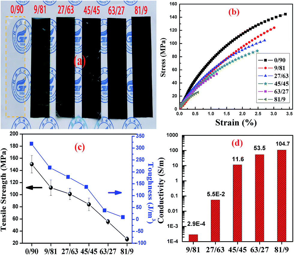 | ||
| Fig. 9 Result of CNC@PANI/CNF/PVA nanocomposites with different mass ratio of CNC@PANI over CNF: (a) digital photograph, (b) stress–strain curve, (c) tensile strength and toughness, (d) conductivity. | ||
 | ||
| Fig. 10 The digital photograph of conductive CNC@PANI/CNF/PVA nanocomposites as conductor to driver a LED. The number is different mass ratio of CNC@PANI over CNF. (a) Without (b) 81/9, (c) 63/27, (d) 45/45, (e) 27/63, (f) 9/81. | ||
4. Conclusions
In this study, the CNC@PANI was prepared under controlled reaction conditions. It was then dispersed and stabilized into an aqueous solution by using CNFs as a dispersant. The dispersion mechanism of CNFs is due to the formation of hydrogen bond interactions with CNC@PANI, resulting in CNFs adsorption on CNC@PANI. On the other hand, CNF can entangle and kinks with CNC@PANI. Then, they form an electrostatic repulsion and steric hindrance, which resulted in the dispersion of CNC@PANI. This indicates that CNFs are an efficient and environmentally-friendly dispersant. More importantly, the CNCs@PANI dispersion was cast to obtain the conductive film, which possess excellent electrical conductivity of 104.7 S m−1. The findings of this study support the idea that CNFs can be applied to increase the stability of nanomaterials.Acknowledgements
The authors would like to acknowledge the National Natural Science Foundation of China (Grant No. 21264005, 51163003), Guangxi Natural Science Foundation of China (Grant No.: 2013GXNSFDA019008), Foundation of Guangxi Ministry-Province Jointly-Constructed Cultivation Base for State Key Laboratory of Processing for Non-ferrous Metal and Featured Materials (13AA-6).References
- D. Li and R. B. Kaner, Chem. Commun., 2005, 3286–3288, 10.1039/b504020e.
- Y. Z. Long, M. M. Li, C. Z. Gu, M. X. Wan, J. L. Duvail, Z. W. Liu and Z. Y. Fan, Prog. Polym. Sci., 2011, 36, 1415–1442 CrossRef CAS.
- S. L. Bai, C. Z. Sun, P. B. Wan, C. Wang, R. X. Luo, Y. P. Li, J. F. Liu and X. M. Sun, Small, 2015, 11, 306–310 CrossRef CAS PubMed.
- L. Wang, Q. Yao, H. Bi, F. Huang, Q. Wang and L. Chen, J. Mater. Chem. A, 2015, 3, 7086–7092 CAS.
- N. Jiang, Q. Ruan, F. Qin, J. Wang and H. Q. Lin, Nanoscale, 2015, 7, 12516–12526 RSC.
- Q. Sheng, D. Zhang, Q. Wu, J. Zheng and H. Tang, Anal. Methods, 2015, 7, 6896–6903 RSC.
- P. Humpolicek, K. A. Radaszkiewicz, V. Kasparkova, J. Stejskal, M. Trchova, Z. Kucekova, H. Vicarova, J. Pachernik, M. Lehocky and A. Minarik, RSC Adv., 2015, 5, 68796–68805 RSC.
- S. Mondal, U. Rana, R. R. Bhattacharjee and S. Malik, RSC Adv., 2014, 4, 57282–57289 RSC.
- H. Zhang, Q. Zhao, S. Zhou, N. Liu, X. Wang, J. Li and F. Wang, J. Power Sources, 2011, 196, 10484–10489 CrossRef CAS.
- Q. Lu, Q. Zhao, H. Zhang, J. Li, X. Wang and F. Wang, ACS Macro Lett., 2013, 2, 92–95 CrossRef CAS.
- A. K. Nath and A. Kumar, Solid State Ionics, 2013, 253, 8–17 CrossRef CAS.
- L. Li, L. Ferng, Y. Wei, C. Yang and H.-F. Ji, J. Colloid Interface Sci., 2012, 381, 11–16 CrossRef CAS PubMed.
- X. Shi, L. Zhang, J. Cai, G. Cheng, H. Zhang, J. Li and X. Wang, Macromolecules, 2011, 44, 4565–4568 CrossRef CAS.
- M. M. Hamedi, A. Hajian, A. B. Fall, K. Hakansson, M. Salajkova, F. Lundell, L. Wagberg and L. A. Berglund, ACS Nano, 2014, 8, 2467–2476 CrossRef CAS PubMed.
- C. Olivier, C. Moreau, P. Bertoncini, H. Bizot, O. Chauvet and B. Cathala, Langmuir, 2012, 28, 12463–12471 CrossRef CAS PubMed.
- N. Minami, Y. J. Kim, K. Miyashita, S. Kazaoui and B. Nalini, Appl. Phys. Lett., 2006, 88, 093123 CrossRef (1–3).
- T. Takahashi, K. Tsunoda, H. Yajima and T. Ishii, Jpn. J. Appl. Phys., Part 1, 2004, 43, 3636–3639 CrossRef CAS.
- Y. J. Tang, Z. B. He, J. A. Mosseler and Y. H. Ni, Cellulose, 2014, 21, 4569–4581 CrossRef CAS.
- P. M. Carrasco, S. Montes, I. Garcia, M. Borghei, H. Jiang, I. Odriozola, G. Cabanero and V. Ruiz, Carbon, 2014, 70, 157–163 CrossRef CAS.
- J. M. Malho, P. Laaksonen, A. Walther, O. Ikkala and M. B. Linder, Biomacromolecules, 2012, 13, 1093–1099 CrossRef CAS PubMed.
- C. Saravanan, Z. He and Y. Ni, BioResources, 2014, 9, 1886–1897 CrossRef.
- A. Kamyshny, J. Steinke and S. Magdassi, Open Appl. Phys. J., 2011, 4, 19–36 CrossRef CAS.
- E. T. Thostenson and T. W. Chou, J. Phys. D: Appl. Phys., 2002, 35, 77–80 CrossRef.
- X. Chen, R. Li, K. Qi and G. Q. Lu, J. Electron. Mater., 2008, 37, 1574–1579 CrossRef CAS.
- L. Onsager, Ann. N. Y. Acad. Sci., 1949, 51, 627–659 CrossRef CAS.
- X. Wu, C. Lu, H. Xu, X. Zhang and Z. Zhou, ACS Appl. Mater. Interfaces, 2014, 6, 21078–21085 CAS.
- M. Wan, Conducting polymers with micro or nanometer structure, Springer, 2008, ch. 2, pp. 18–19 Search PubMed.
Footnote |
| † Electronic supplementary information (ESI) available. See DOI: 10.1039/c5ra19346j |
| This journal is © The Royal Society of Chemistry 2016 |