Gas-permeable hydrophobic tubular membranes for ammonia recovery in bio-electrochemical systems
P.
Kuntke
*a,
P.
Zamora
b,
M.
Saakes
a,
C. J. N.
Buisman
ac and
H. V. M.
Hamelers
a
aWetsus, European Centre of Excellence for Sustainable Water Technology, Oostergoweg 9, 8911 MA Leeuwarden, The Netherlands. E-mail: philipp.kuntke@wetsus.nl
bAbengoa, Campus Palmas Altas, C/ Energía Solar nº 1, 41014 Seville, Spain
cSub-Department of Environmental Technology, Wageningen University, Bornse Weilanden 9, P.O. Box 17, 6700 AA Wageningen, The Netherlands
First published on 4th February 2016
Abstract
The application of a gas-permeable hydrophobic tubular membrane in bio-electrochemical systems enables efficient recovery of ammonia (NH3) from their cathode compartments. Due to a hydrogen evolution reaction at the cathode, no chemical addition was required to increase the pH for continuous NH3 recovery from wastewater.
Water impactAmmonia recovery using bio-electrochemical systems (BESs) has been investigated by various researchers with promising results. Most of the concepts using microbial fuel cells and microbial electrolysis cells rely on ammonia stripping from a catholyte with subsequent absorption in an acid. However, this requires large volumes of gasses (O2, N2, H2) to be recycled or supplied to a cathode compartment, resulting in a potentially high energy demand. Integrating a gas-permeable hydrophobic tubular membrane can lower the energy demand for ammonia recovery from wastewater and also simplify the design of ammonia recovery systems based on BESs. Furthermore, similar approaches for ammonia recovery using electrochemical systems can also benefit from this type of integration. |
1. Introduction
Bio-electrochemical systems (BESs) allow for the recovery of valuable products and energy from wastewater streams.1 BESs use electron active microorganisms to catalyse at least one of the electrode reactions at an anode or cathode. There are two basic types of BESs: microbial fuel cells (MFCs) are galvanic cells which produce electricity2 and microbial electrolysis cells (MECs) are electrolytic cells which produce hydrogen.3 BESs have been applied for the recovery of ammonia and energy (as electricity or hydrogen gas) from wastewater.4,5Recently, BESs have been proposed as a suitable technology for the treatment of urine, which allow for nutrient and energy recovery and provide the opportunity for a suitable business case to bring BESs to the market.5,6
One of the biggest challenges for the energy efficient recovery of ammonia (NH3) from wastewater is the energy required for an NH3-stripping process.7,8 Using BESs, the need for chemical addition to raise the pH of wastewater can be mitigated, but the high energy demand for the supply and recycling of a gas stream to a cathode compartment still remains.9–11
Transmembrane chemisorption (TMCS) has been described as an alternative method for NH3 recovery by NH3-gas transport through a gas-permeable hydrophobic membrane with subsequent NH3-absorption in a suitable acid solution as ammonium (NH4+).12 This eliminates the need for high gas flow rates (several L of gas per L of wastewater) and therefore can lower the energy requirements of NH3 recovery.
In this research, we report the recovery of NH3 by means of a TMCS module integrated in the catholyte compartment of an MEC. Ammonium ions are transported from the anolyte to the catholyte by diffusion and migration. As a result of the pH in the catholyte, the ammonium ions are deprotonated to volatile ammonia gas. The ammonia gas in the catholyte diffuses via the nanometer-sized gas-filled pores of a gas-permeable hydrophobic membrane into an acid.
2. Materials and methods
2.1. Experimental setup
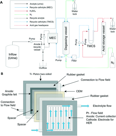
The experimental setup consisted of a MEC with an integrated TMCS module. Fig. 1A illustrates the experimental setup. The MEC was composed of 4 anode and cathode pairs, which were hydraulically and electrically connected in a parallel manner.The MEC was operated in a parallel configuration in which each individual titanium plate either served as an anode or cathode housing. Each titanium plate (with dimensions of 28 cm × 28 cm × 0.8 cm) had a machined and platinized flow field (10 g m−2) with 20 cm × 20 cm × 0.3 cm dimensions on both sides. The platinized flow fields define a flow path for an electrolyte. At the anode side, the flow field also served as an anodic current collector, which a graphite electrode is placed upon. At the cathode side, the flow field also served as a catalyst for a hydrogen evolution reaction (HER). Fig. 1B illustrates one cell pair of the MEC and shows the flow of the electrolyte through one of the half cells (anode or cathode).
The titanium plates were supplied by Magneto Special Anodes B.V. (Schiedam, The Netherlands). The anode electrodes were composed of a graphite felt (GFD 2.5, SGL Group, Bonn, Germany) with dimensions of 20 cm × 20 cm. The total anode surface area was 0.16 m.2 The anode and cathode pairs were separated by a cation exchange membrane (CEM, Ralex CMH-PP, Mega a.s., Czech Republic). Silicone rubber gaskets (0.5 mm, MVQ Silicone, ERIKS, The Netherlands) were used to ensure water tightness. All 4 anode compartments were fed in a parallel manner with the inflow from a common anolyte recycle vessel (0.9 L). Each anode and cathode compartment (8) was equipped with Ag/AgCl reference electrodes (QM710X, Q-i-s, Oosterhout, The Netherlands). Similarly, the 4 cathode compartments were fed in a parallel manner with the inflow from a common recycle vessel. The recycle vessel (degassing vessel) had a volume of 1.5 L and a headspace of 1 L, including a heating jacket for temperature control (LGS, Ubbena, The Netherlands). The cathode compartment was operated in a batch mode, while the catholyte was recycled over a gas-permeable hydrophobic tubular membrane module on the shell side. Inside the gas-permeable hydrophobic tubular membrane (lumen side of the TMCS module), 1 M sulphuric acid solution was recycled from an acid storage vessel (similar to the degassing vessel). Sulphuric acid was used for absorption of ammonia, resulting in an ammonium sulphate solution over time. All the chemicals used were of analytical grade.
Four Masterflex pumps (LS Digital Drive 600, Metrohm Applikon BV, Schiedam, The Netherlands) were used to supply the inflow from the storage tank to the system and different recycle flows over the anodes, cathodes and the gas-permeable hydrophobic tubular membrane module (shell and lumen side). A polyethylene (PE) tubing was used for the gas and liquid transport (DN04/06, Em-Technik, Germany) in the experimental setup. The anode compartment had a hydraulic volume of 1.35 L, whereas the total volume of the anodes (inside the MEC) was 0.32 L.
N2 from a nitrogen generator was supplied to the cathode compartment at 2 to 5 mL min−1 to remove any oxygen from the headspace and provide oxygen-free conditions for the HER.
A power supply (ES 030-5, Delta Elektronika, The Netherlands) was used to apply a constant voltage to the MEC. The electrical connection of the 4 cell pairs (8 electrodes) was made by means of 2 identical aluminium blocks (8 cm × 8 cm × 4 cm), each with 5 drilled connections in a geometric alignment, connected by 7 identical isolated cables (50 cm × 0.1 cm2, 4 mm connector, Hirschmann, Germany).
The pH and temperature were measured in the anode recycle vessel and degassing vessels using pH electrodes (CPS11D) and a two-channel transmitter (Liquiline CM442, Endress+Hauser, Germany). The applied voltage, anode and cathode potentials, current, pH and temperature of the anode and the cathode were recorded with a datalogger (Memograph M RSG40, Endress+Hauser, Germany).
The TMCS module was constructed from a polypropylene (pore size: 200 nm, type: Accurel PP V8/HF) membrane fibre (CUT Membrane Technology GmbH, Düsseldorf, Germany), housed in a custom-made membrane module and operated in a cross flow mode. The TMCS module had a total shell side (outer) membrane surface area of 374 cm2.
2.2. BES operation
The BES was previously operated on wastewater (diluted urine) and was originally inoculated with an effluent from an active cell also operating on urine.9 The anode, cathode and acidic solutions were recycled over their respective vessels at a flow rate of 50 mL min−1. The anodes were fed from the storage tank (50 L) at an inflow rate of 4 mL min−1. During the experiment, the ammonium concentration in the acid was measured on weekdays. The sulphuric acid was renewed when the NH4+ concentration exceeded 15 gN L−1, before the acid reached saturation to ensure sufficient absorption capacity.The cathode recycle and acid recycle vessels were temperature-controlled to 25 ± 1 °C using a water bath DC10-K10 (Thermo Scientific HAAKE, Germany) to ensure an equal temperature and prevent a water vapour gradient across the gas-permeable hydrophobic tubular membrane, and thus minimising the risk of water vapour transport from either sides of the membrane. Samples were taken on weekdays from the anode influent, anode effluent, cathode compartment and acid compartment to determine the BES performance.
Urine samples were collected from the male employees of Wetsus by means of water-free urinals (Urimat®, Biocompact, The Netherlands) and stored in a polyvinyl chloride (PVC) vessel. The urine samples were pre-treated by struvite precipitation and subsequent filtration, as previously described.9 The anolyte inflow was prepared by dilution of the pre-treated urine samples 5× with deionized water to mimic wastewater.
2.3. Chemical analysis
Samples from the anode influent, anode effluent, cathode compartment and acid compartment were analysed according to standard methods13 for relevant parameters such as COD, ammonium-nitrogen, and cation and anion concentration, as previously described.9 All the samples were analysed in duplicate after filtration using 0.45 μm membrane filters. The pH of the collected samples was analysed using a weekly calibrated sensor (ProfiLine pH/Cond 3320 WTW, Germany).The samples from the headspace were analysed with a gas chromatograph (μGC Varian CP 4900, Agilent Technologies, US) for the gas composition.
2.4. Calculations
The performance of the BES was analysed by determining the current density (i), coulombic efficiency (CE), COD removal (RCOD) from the influent, ammonium removal (RN) from the influent, and ammonia transport efficiency over the CEM (ηN) in accordance with described methods.9 The energy requirement for the ammonia recovery was calculated based on the removed ammonium-nitrogen and the electrical energy input of the MEC.3. Results and discussion
3.1. MEC performance
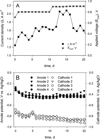
The MEC performance was assessed by the measured current density and the anode and cathode potentials. Fig. 2A shows the current density determined over the 20-day experiment. Although the measured current density (average of 1.7 ± 0.21 A m−2) was considerably lower than earlier reported current densities in BESs treating urine,9 the system showed a stable operation during the whole experimental period. Fig. 2B shows the corresponding anode and cathode potentials during the experimental period, which also indicate a stable operation. | ||
| Fig. 2 (A) Applied cell voltage and measured current density. (B) Measured anode and cathode potentials during the experimental period. | ||
3.2. COD and ammonium removal and efficiencies
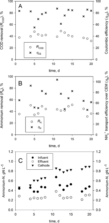
Fig. 3A and B show the COD and ammonium removal as well as the coulombic and ammonium transport efficiencies over the CEM. The Coulombic efficiency (ηCE) and COD removal (ηCOD) indicate a stable operation. On average, a coulombic efficiency of 78 ± 10% and a COD removal of 40 ± 5% were obtained, which are comparable to earlier reported results for BESs operating on urine.9The average ammonium-nitrogen removal throughout the experimental period of 20 days was 42 ± 6%, while the highest removal reached was 51% on days 4 and 15 in this continuous feed BES.
The ammonium transport efficiency over the CEM was 70 ± 17% on average, whereas the highest transport efficiency was 104%, showing that ammonium was the main contributor to the charge transport over the CEM.
While higher ammonium removal efficiencies have been achieved previously at higher current densities in (bio-) electrochemical systems, the charge transport reported in this work was found to be higher than in these respective works.9,14,15
3.3. Ammonium recovery
The pH measurements showed that the anolyte inflow was stable around 9.16 ± 0.16, the anolyte effluent was stable around 7.19 ± 0.3 and the catholyte pH was stable around 9.46 ± 0.19. Therefore, the ammonium-nitrogen (i.e. NH3 & NH4+) present in the inflow was transported as NH4+ from the anode to the cathode over the CEM, from where it was removed as NH3 over the gas-permeable hydrophobic tubular membrane and concentrated as NH4+ in sulphuric acid.Fig. 3C shows the ammonium-nitrogen (NH3-N & NH4+-N) concentration during the experiment. The ammonium-nitrogen concentration in the anolyte effluent and the catholyte were 42 ± 6% lower and 59 ± 33% higher on average than in the anolyte influent.
The highest NH4+-N concentration reached in the acid was 22.5 gN L−1, which corresponds to a concentration factor of 45 times the NH4+-N concentration in the corresponding inflow of the BES. About 95% of the ammonium-nitrogen removed from the anolyte during this period (day 11 to 15) was recovered in sulphuric acid. Overall, a maximum ammonium-nitrogen recovery of 49% from the influent was reached on day 15, which is slightly lower than the 57% recovery reported in an electrochemical system (ES).15 These results show that it is possible to concentrate ammonium-nitrogen from the anolyte in the acid. Additionally, our experimental setup is less complex than other experimental setups using gas recirculation14,15 or a multiple absorption vessel.11 While sulphuric acid is a practical solution for ammonia recovery, alternatives (i.e. phosphoric acid or nitric acid) should be considered in order to produce a high-value fertilizer.
The limitation of this BES was the relatively low current density reached in the experiments, whereas high NH4+ transport efficiency over the CEM (∼70 ± 17%) and good recoveries from the catholyte were achieved (∼95%).
3.4. Energy demand
The energy demand for the ammonia recovery was 2.49 ± 0.67 kWh gN−1 on average, which is considerably lower than the energy demand of an ES (i.e., 5 to 12 kWh gN−1)14,15 and only slightly higher than other BESs (1.35 ± 0.39 kWh gN−1†)10 operating at higher current densities. However, the lower energy demand of the BES was a result from the constantly replenished catholyte, leading to lower potential losses.9 Potential benefits to the energy demand of the ammonia recovery from the produced hydrogen were not considered in our experiments. Furthermore, a detailed energy analysis should also include the energy for pumps (inflow and recycling).4. Conclusions
Our results show that gas-permeable hydrophobic membranes can be successfully employed in a BES for ammonia recovery from wastewater. The energy demand of this system is considerably lower than the energy demand of an ES for ammonia recovery. Furthermore, gas-permeable hydrophobic membranes could be either directly integrated in the cathode compartment or be part of the recycle stream of the catholyte, resulting in less complex treatment systems. These configurations can also be beneficial for other (bio-) electrochemical systems in order to simplify the design of an ammonia recovery setup. Although the results are promising, further research will be necessary to increase ammonium removal rates.Acknowledgements
This work was performed in the cooperation framework of Wetsus, European Centre of Excellence for Sustainable Water Technology (http://www.wetsus.eu). Wetsus is co-funded by the Dutch Ministry of Economic Affairs and Ministry of Infrastructure and Environment, the European Union Regional Development Fund, the Province of Fryslân, and the Northern Netherlands Provinces. This research has received funding from the European Union's Seventh Programme for research, technological development and demonstration under grant agreement No 308535. The authors would like to thank the participants of the research theme “Resource Recovery” for the fruitful discussions and their financial support. The authors would also like to thank Martin Ulbricht from 3M for support on the TMCS membranes. Furthermore, the authors would like to thank the reviewers for their valuable input.Notes and references
- H. V. M. Hamelers, A. Ter Heijne, T. Sleutels, A. W. Jeremiasse, D. Strik and C. J. N. Buisman, Appl. Microbiol. Biotechnol., 2010, 85, 1673–1685 CrossRef CAS PubMed.
- B. E. Logan, B. Hamelers, R. A. Rozendal, U. Schröder, J. Keller, S. Freguia, P. Aelterman, W. Verstraete and K. Rabaey, Environ. Sci. Technol., 2006, 40, 5181–5192 CrossRef CAS PubMed.
- B. E. Logan, D. Call, S. Cheng, H. V. M. Hamelers, T. H. J. A. Sleutels, A. W. Jeremiasse and R. A. Rozendal, Environ. Sci. Technol., 2008, 42, 8630–8640 CrossRef CAS PubMed.
- P. T. Kelly and Z. He, Bioresour. Technol., 2014, 153, 351–360 CrossRef CAS PubMed.
- M. Rodriguez Arredondo, P. Kuntke, A. W. Jeremiasse, T. H. J. A. Sleutels, C. J. N. Buisman and A. ter Heijne, Environ. Sci.: Water Res. Technol., 2015, 1, 22–33 CAS.
- P. Ledezma, P. Kuntke, C. J. N. Buisman, J. Keller and S. Freguia, Trends Biotechnol., 2015, 33, 214–220 CrossRef CAS PubMed.
- M. Maurer, W. Pronk and T. A. Larsen, Water Res., 2006, 40, 3151–3166 CrossRef CAS PubMed.
- M. Maurer, P. Schwegler and T. A. Larsen, Water Sci. Technol., 2003, 48, 37–46 CAS.
- P. Kuntke, T. H. J. A. Sleutels, M. Saakes and C. J. N. Buisman, Int. J. Hydrogen Energy, 2014, 39, 4771–4778 CrossRef CAS.
- P. Kuntke, K. Śmiech, H. Bruning, G. Zeeman, M. Saakes, T. Sleutels, H. Hamelers and C. Buisman, Water Res., 2012, 46, 2627–2636 CrossRef CAS PubMed.
- X. Wu and O. Modin, Bioresour. Technol., 2013, 146, 530–536 CrossRef CAS PubMed.
- M. Ulbricht, J. Schneider, M. Stasiak and A. Sengupta, Chem. Ing. Tech., 2013, 85, 1259–1262 CrossRef CAS.
- L. S. Clesceri, A. D. Eaton, A. E. Greenberg, A. P. H. Association, A. W. W. Association and W. E. Federation, Standard Methods for the Examination of Water and Wastewater, American Public Health Association, 1998 Search PubMed.
- J. Desloover, A. Abate Woldeyohannis, W. Verstraete, N. Boon and K. Rabaey, Environ. Sci. Technol., 2012, 46, 12209–12216 CrossRef CAS PubMed.
- A. K. Luther, J. Desloover, D. E. Fennell and K. Rabaey, Water Res., 2015, 87, 367–377 CrossRef CAS PubMed.
Footnote |
| † Calculated from the reported values by Kuntke et al., 2014.10 |
| This journal is © The Royal Society of Chemistry 2016 |


