 Open Access Article
Creative Commons Attribution 3.0 Unported Licence
The crystallisation of copper(II) phenylphosphonates†
Manuel
Wilke
ac,
Anke
Kabelitz
ac,
Tatiana E.
Gorelik
b,
Ana Guilherme
Buzanich
a,
Uwe
Reinholz
a,
Ute
Kolb
b,
Klaus
Rademann
c and
Franziska
Emmerling
*a
aBAM Federal Institute for Materials Research and Testing, Richard-Willstätter-Straße 11, 12489 Berlin, Germany. E-mail: franziska.emmerling@bam.de; Fax: +49 30 8104 1137; Tel: +49 30 8104 1133
bInstitute of Physical Chemistry, Johannes Gutenberg-University, Welderweg 11, 55128 Mainz, Germany
cDepartment of Chemistry, Humboldt-Universität zu Berlin, Brook-Taylor-Str. 2, 12489 Berlin, Germany
First published on 6th October 2016
Abstract
The crystal structures and syntheses of four different copper(II) phenylphosphonates, the monophenylphosphonates α-, β-, and γ-Cu(O3PC6H5)·H2O (α-CuPhPmH (1) β-CuPhPmH (2) and γ-CuPhPmH (3)), and the diphosphonate Cu(HO3PC6H5)2·H2O (CuPhP2mH (4)), are presented. The compounds were synthesized from solution at room temperature, at elevated temperature, under hydrothermal conditions, and mechanochemical conditions. The structures of α-CuPhPmH (1) and CuPhP2mH (4) were solved from powder X-ray diffraction data. The structure of β-CuPhPmH (2) was solved by single crystal X-ray analysis. The structures were validated by extended X-ray absorption fine structure (EXAFS) and DTA analyses. Disorder of the crystal structure was elucidated by electron diffraction. The relationship between the compounds and their reaction pathways were investigated by in situ synchrotron measurements.
Introduction
Metal phosphonates can form a wide range of structural architectures, ranging from isolated complexes to three-dimensional frameworks. The structural variability results in different properties and applications.1–4 Molecular metal phosphonates are of interest due to their catalytic and magnetic properties. The higher dimensional structures are coordination polymers (CP5) and are candidates for classical application in gas storage and catalysis.6–9 The materials can be used as proton conductors and for the modification of surfaces because of their polar pores and different organic groups.10–16 Zirconium(IV) phenylphosphonate was one of the first described metal phosphonates.17 Cunningham et al. showed different syntheses of divalent metal phenylphosphonates with the general formula M(II)(O3PC6H5)·H2O.18 The authors identified four polymorphs of copper(II) phenylphosphonate monohydrate (CuPhPmH), but they were not able to solve the structures from the obtained powder diffraction data. A layered structure and an octahedral coordination of the central metal were proposed. Mallouk et al. were able to solve the structure of the manganese phenylphosphonate monohydrate and could show that the divalent metal phenylphosphonates are isomorphic.19 An exception is a CuPhPmH compound, characterized by Clearfield et al.20 Here, the copper-ion is coordinated in a distorted tetragonal pyramid. Nowadays, metal phosphonate chemistry is intensively studied. High-throughput syntheses were developed.21 Structure solutions are performed increasingly from powder X-ray diffraction (PXRD) data.12,13,22,23 Recently, mechanochemical syntheses of metal phosphonates were described.23–25Here, we present the syntheses, characterization, and crystal structures of three polymorphs of CuPhPmH (1–3) and a copper(II) phenylphosphonate containing two monodeprotonated phenylphosphonate ligands Cu(HO3PC6H5)2·H2O (CuPhP2mH (4)). The existence of the three polymorphs was described by Cunningham et al.18 The compounds were named α-CuPhPmH (1), β-CuPhPmH (2), and γ-CuPhPmH (3). The polymorph γ-CuPhPmH (3) was described by Clearfield et al.20 We present different synthesis routes including solvent-based synthesis at ambient conditions, at elevated temperatures, hydrothermal, and mechanochemical synthesis. The crystal structures were solved from powder and single crystal XRD data. The structures were further characterized by extended X-ray absorption fine structure (EXAFS) and DTA analyses. Some of the polymorphs showed diffuse scattering in single-crystal electron diffraction data which is one of the reasons why the crystal structures were unresolved so far. Therefore, we put a particular focus on analysing the disorder in the structures. Finally, we also report on mechanistic studies conducted in situ using synchrotron XRD.
Experimental section
Chemicals
The following chemicals were used: copper(II) acetate monohydrate (cryst. extra pure, Merck, Germany), copper(II) sulfate pentahydrate (p.a., AplliChem, USA), phenylphosphonic acid (98%, Acros Organics, USA), urea (puriss., Riedel-de Haën, Germany), boron nitride (99.5%, Alfa Aesar, Germany), hydrochloric acid (37%, Fisher Chemical, USA), methanol (99.8+%, Acros Organics, USA), acetone (99.5%, Chem. Solute, Germany) and MilliQ water (18.2 MΩ, ultrapure water system seralpur Pro 90 CN, Seral, Germany). All chemicals were used without further purification.Analytical techniques
PXRD patterns were collected with Cu Kα radiation (λ = 1.54056 nm) on a D8 Discover diffractometer (Bruker AXS, Germany) equipped with a Lynxeye detector. Samples were measured in transmission geometry in a 2θ range from 4° to 60° with a step size of 0.009°. For structure solution the measurement time per step was 20 s.Single crystal XRD measurements were performed on a D8 Venture diffractometer (Bruker AXS, Germany) using Mo Kα radiation (λ = 0.71073 nm) monochromatized by a graphite crystal.
In situ and ex situ investigations of all reactions using synchrotron XRD were performed at the μSpot beamline (Bessy-II, Helmholtz Centre Berlin for Materials and Energy, Berlin, Germany).26 The scattered intensities were collected with a two-dimensional MarMosaic CCD detector with 3072 × 3072 pixels (pixel size 73 μm). In situ investigations of the mechanochemical reactions were performed as described elsewhere.25 Further details are given in the ESI.†In situ investigations of precipitation reactions were conducted with the stopped-flow module SFM3000 (Bio-Logic SAS, France) equipped with a capillary head. A detailed description and a representation of the setup is given in the ESI.† Two modes of operation could be used. (i) Certain points in time of the reaction were investigated while the reaction mixture was flowing constantly through the capillary. (ii) Scan measurements over a longer time-period were taken with the reaction mixture stored in the horizontal capillary holder. All obtained scattering images were processed employing an algorithm of the computer program FIT2D.27 For the graphical representations, scattering vector (q) values were transformed to the diffraction angle 2θ for Cu Kα radiation to provide a direct comparison to results obtained in laboratory PXRD experiments.
The EXAFS measurements were performed at the BAMline (Bessy-II, Helmholtz Centre Berlin for Materials and Energy Berlin, Germany).28 The experimental conditions and data processing are described in the ESI.†
TEM work was done using a FEI TECNAI F30 TEM operated at 300 kV with a field emission gun. Electron diffraction tomography data was collected using the automated acquisition module described elsewhere.29 The data was collected using a high-tilt Fischione tomography holder within the tilting range of ±60°, with a tilt step of 1°, at room temperature and at liquid nitrogen temperature. During the acquisition the electron dose rate was kept as low as 1 e Å−2 s−1. The data was processed using the dedicated software ADT3D (Nanomegas, Brussels, Belgium). Electron diffraction patterns were simulated using the eMap software (Analitex, Stockholm, Sweden).
Structure solution and refinement
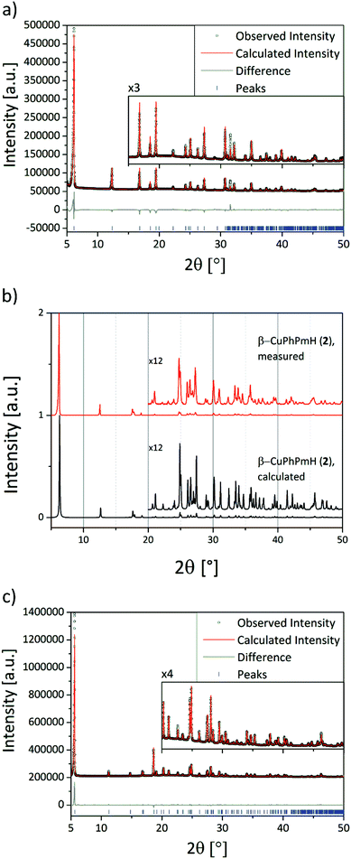
The structure solution of α-CuPhPmH (1) was conducted from PXRD data. The powder data were indexed using the indexing routine of the software TOPAS (version 5, Bruker AXS, 2014). The resulting lattice constants are similar to crystal data of a group of isomorphous compounds with the formula M(II)(O3PC6H5)·H2O. The structure of the new compound was solved starting from the structure of Fe(O3PC6H5)·H2O.22 Simulated annealing was conducted in EXPO2014.30 The Rietveld refinement was performed using TOPAS. The final Rietveld and difference plots are shown in Fig. 1a. Two possible positions of the phenyl rings were detected.The structure solution of β-CuPhPmH (2) was conducted from single crystal XRD data. A blue plate like crystal of the product was measured at 180 K. The data reduction was performed using the Bruker AXS SAINT and SADABS packages. The structure was solved using direct methods and refined by full-matrix least squares calculation using SHELX.31,32
Anisotropic thermal parameters were refined for non-hydrogen atoms. The hydrogen atoms were treated isotropically with Uiso = 1.2 times the Ueq value of the parent atom. A comparison of the measured PXRD pattern with the calculated PXRD pattern from the crystal data for that structure is shown in Fig. 1b.
The structure solution of CuPhP2mH (4) was conducted from PXRD data. The diffraction pattern was indexed using the N-TREOR program implemented in the EXPO software. The structure was solved using the simulated annealing routine implemented in DASH.33 The position of the copper atom was fixed at (0, 0, 0). The Rietveld refinement was performed using TOPAS. The final Rietveld and difference plots are shown in Fig. 1c. Selected bond length and angles for all new structures are shown in Tables S1–S3.†
Missing hydrogen atoms were inserted according to the directions of the hydrogen bonds.
The final crystal data and figure of merits of all compounds are listed in Table 1. CCDC 1490687, 1490688 and 1490689 contain the supplementary crystallographic data for α-CuPhPmH (1), β-CuPhPmH (2), and CuPhPmH (4).
| (1) | (2) | (3)20 | (4) | |
|---|---|---|---|---|
| Empirical formula | CuC6H7O4P | CuC6H7O4P | CuC6H7O4P | CuC12H14O7P2 |
| Formula weight/g mol−1 | 237.64 | 237.64 | 237.64 | 395.73 |
| Crystal system | Orthorhombic | Monoclinic | Orthorhombic | Monoclinic |
| Space group | Pmn21 | P21/c | Pbca | C2/c |
| a/Å | 5.6591(2) | 13.9871(7) | 7.5547(4) | 31.6114(2) |
| b/Å | 14.3406(5) | 7.6637(4) | 7.4478(6) | 6.0867(1) |
| c/Å | 4.7964(1) | 7.4534(4) | 27.982(1) | 7.6257(1) |
| β/° | 90 | 91.750(2) | 90 | 97.5309(9) |
| V/Å3 | 389.25(2) | 798.58(7) | 1574.43 | 1454.60(2) |
| Z | 2 | 4 | 8 | 4 |
| D calc/g cm−3 | 2.028 | 1.976 | 2.005 | 1.807 |
| Temperature/K | 293 | 180 | 293 | |
| R wp | 10.46 | 3.29 | ||
| R Bragg | 8.225 | 6.62 | ||
| GOF | 8.91 | 2.98 | ||
| Goodness-of-fit on F2 | 1.109 | |||
| R [I > 2σ(I)] | 0.0318 | |||
| wR (all data) | 0.0820 |
The crystal structures were validated by EXAFS measurements. The EXAFS data for all compounds are shown in Fig. S3–S6,† and the fit parameters are shown in Tables S3–S6† for compound (1)–(4).
For all compounds DTA-TG measurements were performed. In all cases a loss of the crystal water could be obtained. The data is given in Fig. S8–S11.†
Results and discussion
Structure description
The structure of α-CuPhPmH (1) is shown in Fig. 2a along the c-axis. The structure is isomorphic to the group of divalent metal phenylphosphonate monohydrates M(II)(O3PC6H5)·H2O with M = Mn,19 Fe,22 Co,34 Ni,35 Zn,36 and Cd.37 The Cu2+-ion is coordinated by five oxygen atoms of four different phenylphosphonate ligands and one oxygen atom of a water molecule. The result is a strongly distorted octahedral coordination. The Cu–O-bond lengths range from 2.00(2) Å to 2.24(2) Å. The O–Cu–O angles of neighbouring O-atoms range from 61.2(4)° to 100.9(4)°. These octahedra are corner-connected and form a layered structure. All oxygen atoms of the phosphonate group are included in the coordination. Two of them chelate one Cu2+-ion and bridge at the same time two other Cu2+-ions. The third oxygen atom (O1) coordinates to another Cu2+-ion. Perpendicular to the layer, the phenyl rings are arranged alternating above and below the layer. The phenyl rings connect the layers via van der Waals forces. The orientation of the phenyl rings is disordered. There are two half-occupied positions, perpendicular to each other and rotated around the C1–P1 axis.The structure of β-CuPhPmH (2) is shown in Fig. 2b along the b-axis. It is related to the structure of γ-CuPhPmH (3), described by Clearfield et al. (see Fig. 2c).20 The inner layer structure of both compounds is similar. The Cu2+-ion is coordinated by five oxygen atoms forming a distorted tetragonal pyramid. Three oxygen atoms in the plane and the one at the top stem from four different phenylphosphonate ligands. The coordination is completed by a water molecule. For β-CuPhPmH (2) the lengths of the Cu–O-bonds in the plane differ from 1.925(2) Å to 1.992(2) Å and at the top the bond length amounts to 2.343(2) Å.
The distortion of the pyramid becomes apparent from the values of the respective angles. The angles between one oxygen atom of the plane, the Cu2+-ion and the oxygen atom in the top range from 81.41(6)° to 109.26(6)°. Two of such pyramids build pairs. They share two oxygen atoms from two phenylphosphonate ligands and are connected via one edge. These Cu2O8-pairs are only connected by the phosphonate group. The lengths of the three P–O-bonds differ only in a small range from 1.527(2)–1.536(2) Å. All values are very similar to the structure data of γ-CuPhPmH (3).
The difference between the two structures is the position of the phenyl rings between the layers and the resulting different layer stacking. In β-CuPhPmH (2) the phenyl rings adopt only one orientation. Seen along the b-axis, the phenyl rings are tilted compared to the layer build by the CuO5-pyramids. The angle between the C1, P1 and an adjacent P1 atom is 82.13(7)°. The phenyl rings bound to the same layer are perpendicular to each other. Since the β-angle (91.750(2)°) is almost orthogonal, the length of the a-axis is approximately the layer distance.
γ-CuPhPmH (3) contains two kinds of layers. One layer is the same as described for β-CuPhPmH (2). For the second layer the described tilting of the phenyl ring is in the opposite direction. The comparable angles are 81.3(2)° for one kind of layer and 99.3(2) for the other one. The layers are arranged in an alternating manner. As a result, the unit cell has a doubled volume and its symmetry is orthorhombic. Following the structure described by Clearfield et al. the distance between the layers is half of the c-axis. Consequently, this c-axis is about twice the size of the a-axis of the unit cell of β-CuPhPmH (2). The other two axes are very similar.
The structure of CuPhPmH2 (4) is shown in Fig. 2d along the c-axis. The Cu2+-ion is coordinated by six oxygen atoms stemming from four phenylphosphonate ligands and two water molecules. The resulting octahedron is only slightly distorted. The Cu–O bond range from 1.934(3) Å to 2.312(2) Å and the O–Cu–O angle from 88.0(1)° to 92.0(1)°. Two oxygen atoms of the phenylphosphonate ligand coordinate to two different Cu2+-atoms. The third oxygen (O1) is protonated and is not engaged in the coordination. The water molecule bridges two Cu2+-ions. As a result, the octahedra are corner-connected via the water molecule and in addition are connected by two phosphonate groups. The CuO6-octahedra form a chain structure. The chains are connected via strong and moderate hydrogen bonds (dO1–O2 = 2.439(3) Å, dO4–O1 = 2.543(3) Å). As a result, a layered structure is formed. These layers are connected via van der Waals forces between the phenyl rings, which point into the interlayer space.
The EXAFS data for all compounds and the respective fit with the obtained structures are in good agreement (R = 0.028 for (1), 0.015 for (2), 0.010 for (3), 0.010 for (4)). With RMSE (root mean square error) values of 0.197 Å for (1), 0.051 Å for (2), 0.040 Å for (3), and 0.089 Å for (4) the positions at the first coordination shell are proven.
The existence of anhydrous copper(II) phenylphosphonates, as suggested by Cunningham et al., is discussed in the ESI.†18
The stacking disorder in copper phenylphosphonates
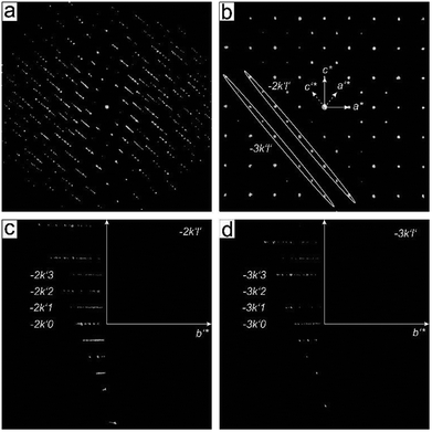
The presence of disorder in metal phenylphosphonates was already reported by Cao et al.19 The appearance of weak additional reflections doubling the unit cell was assigned to an ordering of the phenyl rings. Attempts to refine the structure using a larger unit cell did not improve the structure refinement. Diffuse scattering was observed for different metal phenylphosphonates,22,34–36 but no attempt to clarify possible structure models was undertaken.The partial ordering of the phenyl rings should appear as background diffuse scattering between the Bragg reflections.38 In contrast, the diffuse scattering observed in the diffraction data of phenylphosphonates appears as smeared reflections lines in the reciprocal volume. These effects are usually associated with stacking faults in a layered structure. Electron diffraction data of α-CuPhPmH (1) is shown in Fig. 3. Fig. 3b shows the unit cell vectors as defined by Cao et al. (a* and c*). It is evident that these vectors do not describe all observed reflections. The complete reciprocal space can be described by the new unit cell vectors a′*, b*, c′*, giving the unit cell a metric of a = 7.4152 Å, b = 14.3363 Å, c = 7.4152 Å, α = 90°, β = 99.4322°, γ = 90°.
Cao et al. defined the unit cell based on discrete reflections eliminating the diffuse scattering. The newly defined unit cell comprises of the rows of discrete reflections as well as diffuse lines. Two planar cuts of the reciprocal space marked in Fig. 3b by ellipses are presented in Fig. 3c and d. One can see an alternating sequence of diffuse and discrete lines, so that the diffuse scattering is “extinct” for the rows h′k′l′ with h′ + l′ = 2n. So, the rows −2k′0, −2k′2 (Fig. 3c) and −3k′1, −3k′3 (Fig. 3d) do not bear the diffuse scattering.
So far the doubling of the unit cell does not make much sense as the structure can easily be reduced back to the initial basis; one needs to split the average structure into the two different conformations present in the new cell.
Packing of the phenyl rings can to some extent be approximated by the packing of benzene molecules. The benzene molecules create a sandwich configuration (as a result of π–π stacking), orthogonal T-shaped conformation, and a parallel-displaced conformation.39 The energy minimum for the sandwich conformation is reached at the intermolecular distance of 3.7–3.9 Å, the typical value for interplanar distance between the planar conjugated moieties. The T-shaped benzene molecular dimer is the most stable at the distance of 4.9–5.0 Å; here one molecule is looking into the plane of the other. This situation is realized in the β-CuPhPmH (2) structure.
Transferring this information to our system of the phenyl rings attached to a relatively rigid inorganic layer, we can say that if the phenyl rings are placed at distances close to 4 Å, they will try to stack parallel, if they are separated by 5 Å, they will form a T-shaped orthogonal packing. This situation is realized in the β-CuPhPmH (2), the neighbouring phenyl rings have a distance of 4.944 Å and 5.778 Å and are arranged at an angle of 84°. The structure does not show any unambiguity in the position of the phenyl rings and no diffuse scattering in the data.
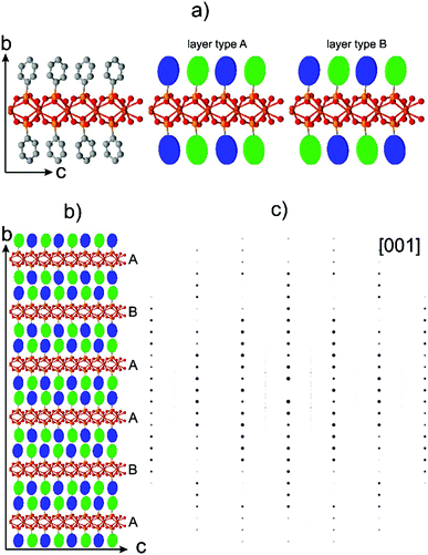
Approximately the same distance between the phenyl rings is realized in the structure of α-CuPhPmH (1): 4.796 Å and 5.659 Å, which allows proposing the same configuration of the phenyl rings: the T-conformation. Thus the disorder cannot be caused by the phenyl-ring arrangement within one layer – they all will be placed orthogonally to each other. Noticeably, the two adjacent layers have a well-defined rule on how they click to each other defined by the phenyl ring orientation (see Fig. 4b).
The orthogonal orientation of the rings allows a chemically sensible splitting of the two phenyls within a newly defined doubled unit cell of the α-CuPhPmH (1) structure. A layer element of the structure with orthogonally arranged phenyl rings is shown in Fig. 4a. The rings are arranged as alternating tilted left or right in the orthogonal manner. For simplicity, the tilting positions of the rings are color-coded as blue and green disks.
The top and the bottom layers of the rings are not in a direct contact. In principle two layer types can be realized – layer type A with the mirrored sequence of the rings and layer type B with a half of a c-vector shifted sequence. An example of an irregular sequence of the layers ABAABA is shown in Fig. 4b. Note, that the clicking rule between the adjacent phenyl rings is well-defined as in the β-CuPhPmH (2) structure.
A simulated electron diffraction pattern of the model shown in Fig. 4b is presented in the Fig. 4c. The simulated diffraction pattern reproduces the general diffuse scattering distribution in the experimental data well: each of h + l = 2n rods consist of discrete reflections, while all of h + l ≠ 2n rods are diffuse (Fig. 3).
The disorder in the α-CuPhPmH (1) is essentially reduced to the random stacking of layers with a shift vector of [0.5 0.5 0] translation of the structure. This produces a diffuse scattering pattern in the reciprocal space with alternating diffuse and discrete reflection rows as described earlier.
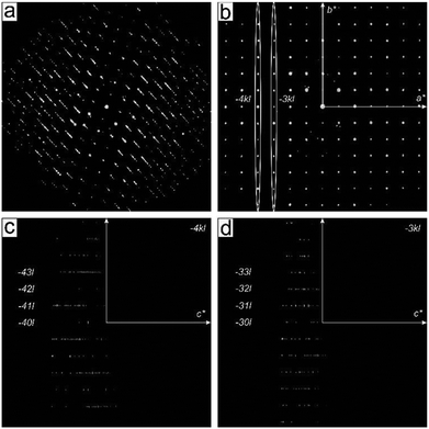
A careful inspection of the diffuse scattering in γ-CuPhPmH (3) (Fig. 5) shows that in contrast to the α-CuPhPmH (1) phase, the rows with discrete reflections are not strictly discrete but possess a diffuse component. The cuts through the reciprocal space representing the −4kl and −3kl planes are shown in Fig. 5c and d. The rows −41l, −43l, −30l, −32l are completely diffuse, while the other rows show a discrete sequence with the fine diffuse content, breaking the h + l ≠ 2n extinction condition for diffuse scattering. Thus, apart from the [0.5 0.5 0] layers shift, another type of disorder must be present in the structure.
The structure of γ-CuPhPmH (3) can be described as a regular packing of two types of layers – A and B related by gliding mirroring. One can easily imagine stacking faults in the structure caused by an irregular sequence of the layers. The interface between A and B layers is given by the average crystal structure and is optimal from the point of phenyl rings packing. The interface between the layers of the same type (AA and BB) has to be optimized by a layer shift in order to achieve the optimal packing of the phenyl groups. The shift with a vector of [0 0.034 0] at the AA and BB interfaces allowed the maintaining of the proper geometry of the phenyl rings between the layers. The sequence with a shift vector which is not a rational fraction of the unit cell creates a model which does not have any defined periodicity in the (a, b) direction. As a result all reflection rows in the simulated diffraction pattern (Fig. 5d) contain diffuse intensities along the c* direction.
Mechanistic studies of precipitation reactions
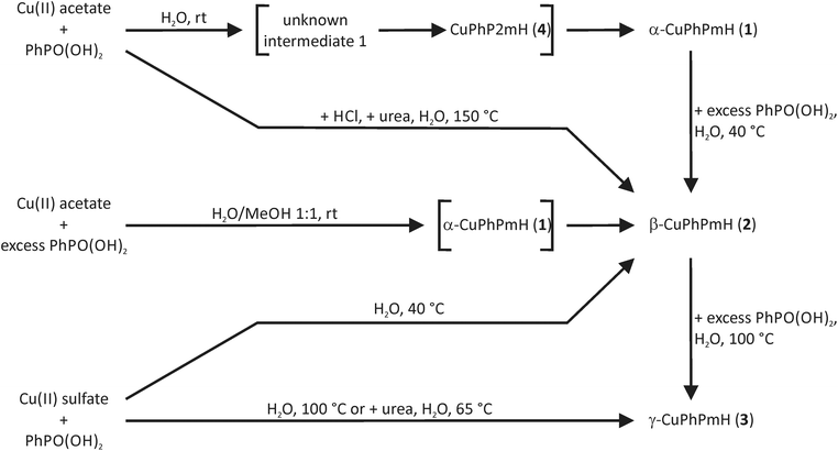
The finally formed product in precipitation reactions depends on the pH value of the reaction solution, the temperature and the solvent.The synthesis of α-CuPhPmH (1) can be easily performed by the addition of an aqueous phenylphosphonic acid solution to an aqueous copper(II) acetate solution at room temperature. The product precipitates immediately. No precipitate can be obtained using copper(II) sulfate pentahydrate. The reason is the pH value of the copper(II) salt solutions. The basic acetate ion leads to a higher pH value (5.8) than the sulfate ion (4.2). The addition of a sodium hydroxide solution (10%) to the reaction mixture with copper(II) sulfate results consistently in an immediate precipitation of α-CuPhPmH (1). The existence of β-CuPhPmH (2) as a side product depends on the sodium hydroxide addition. A fast addition of a larger amount of the sodium hydroxide solution results in a higher ratio of β-CuPhPmH (2).
Heating the mixture of aqueous solutions of copper(II) sulfate and phenylphosphonic acid results either in precipitation of β-CuPhPmH (2) or γ-CuPhPmH (3). At high temperatures (>60 °C) only γ-CuPhPmH (3) is formed. With decreasing temperature the formation of β-CuPhPmH (2) can be observed. As described by Cunningham et al. it is also possible to convert the CuPhPmH phases by solid–solid-transformation. The stirring of α-CuPhPmH (1) in an aqueous phenylphosphonic acid solution at 40 °C results in β-CuPhPmH (2). γ-CuPhPmH (3) can be obtained as product by stirring α-CuPhPmH (1) or β-CuPhPmH (2) in an aqueous phenylphosphonic acid solution at 100 °C.
The product formation can also be influenced by the solvent. The reaction of 599 mg (3 mmol) copper(II) acetate monohydrate with 632 mg (4 mmol) phenylphosphonic acid in 60 mL of a 1![[thin space (1/6-em)]](https://www.rsc.org/images/entities/char_2009.gif) :
:![[thin space (1/6-em)]](https://www.rsc.org/images/entities/char_2009.gif) 1 mixture of water and methanol was investigated by in situ synchrotron PXRD. Using the stopped-flow module and a custom-made extension the reaction mixture was inserted into a capillary and left for 15 min. The resulting PXRD patterns of the time dependent scan measurement are shown in Fig. 6. The first pattern shows only reflections of α-CuPhPmH (1) (e.g. 6.1°, 12.3°, 16.8°, 19.5°). During the next minutes, these reflections vanish and reflections of β-CuPhPmH (2) or γ-CuPhPmH (3) appear. The reflection of the final product at 17.7° appears after 1.00 min and increases in the next minutes. The two reflections of α-CuPhPmH (1) at 16.8° and 19.5° start to vanish after 2.15 min. No reflections of α-CuPhPmH (1) could be detected after 7.00 min of reaction time. In agreement with the investigated reaction pathway, a colour change of the precipitate from white to blue could be obtained in the lab synthesis. A comparison of the PXRD pattern of the final product with the calculated PXRD patterns of β-CuPhPmH (2) and γ-CuPhPmH (3) shows that it is more probably β-CuPhPmH (2), but the crystallinity is weak and a mixture of both phases, β-CuPhPmH (2) and γ-CuPhPmH (3), cannot be ruled out (Fig. S12†).
1 mixture of water and methanol was investigated by in situ synchrotron PXRD. Using the stopped-flow module and a custom-made extension the reaction mixture was inserted into a capillary and left for 15 min. The resulting PXRD patterns of the time dependent scan measurement are shown in Fig. 6. The first pattern shows only reflections of α-CuPhPmH (1) (e.g. 6.1°, 12.3°, 16.8°, 19.5°). During the next minutes, these reflections vanish and reflections of β-CuPhPmH (2) or γ-CuPhPmH (3) appear. The reflection of the final product at 17.7° appears after 1.00 min and increases in the next minutes. The two reflections of α-CuPhPmH (1) at 16.8° and 19.5° start to vanish after 2.15 min. No reflections of α-CuPhPmH (1) could be detected after 7.00 min of reaction time. In agreement with the investigated reaction pathway, a colour change of the precipitate from white to blue could be obtained in the lab synthesis. A comparison of the PXRD pattern of the final product with the calculated PXRD patterns of β-CuPhPmH (2) and γ-CuPhPmH (3) shows that it is more probably β-CuPhPmH (2), but the crystallinity is weak and a mixture of both phases, β-CuPhPmH (2) and γ-CuPhPmH (3), cannot be ruled out (Fig. S12†).
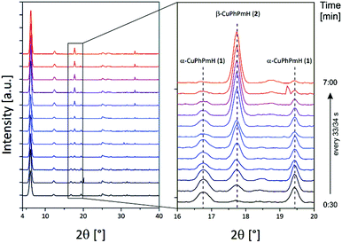 | ||
| Fig. 6 PXRD patterns of the in situ investigation of the phase change of α-CuPhPmH (1) to β-CuPhPmH (2) (see text). | ||
The results indicate that in solution the formation of α-CuPhPmH (1) is kinetically favoured. The thermodynamic favoured product is γ-CuPhPmH (3). The balance between these three polymorphs is susceptible and can be influenced by the pH-value, using one starting material in excess, using methanol as solvent and by heating.
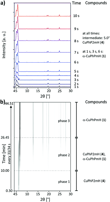
The synthesis of α-CuPhPmH (1) was investigated in situ using synchrotron PXRD and the SFM setup, described in the Experimental section. The first seconds of the reaction were investigated as specific points in time. The resulting powder patterns are shown in Fig. 7a for 1–10 s. A reflection at 5.0° could be detected in all measurements, suggesting the existence of an unknown intermediate. With increasing reaction time, the intensity of the reflection decreases. The unknown compound is probably a layered metal phosphonate, evident from the strong reflection at very low 2θ. A second reflection at 5.6°, observable at all points in time, suggests the intermediate formation of CuPhP2mH (4). Its intensity increases with time. At 1 s, 3 s, and 6 s a reflection at 6.1° indicates the formation of α-CuPhPmH (1). Since this reflection occurs in an irregular manner, α-CuPhPmH (1) seems to be formed spontaneously without being stable at this time in the reaction. Fig. 7b shows the results of the scan measurement over 45 min represented as 2D plot. In the first 10 min only a reflection at 5.6° can be detected which can be assigned to CuPhP2mH (4). Reflections of the final product can be detected after 10 min. During the next minutes the intensity of the reflection at 5.6° started decreasing while at the same time the reflection at 6.1° increased and more reflections of α-CuPhPmH (1) appeared. After 26.45 min the reaction was finished, only reflections of α-CuPhPmH (1) could be detected. The unknown intermediate, observed in the measurements of the short reaction times, could not be detected in the scan measurement. Since a single measurement takes 30 s, the time resolution of the scan measurements is also 30 s. Probably, this intermediate does not persist long enough for a detection in this setup. Clearly, CuPhP2mH (4) is an intermediate formed before α-CuPhPmH (1). Following Ostwald's rule of stages, CuPhP2mH (4) has to be less stable than α-CuPhPmH (1). With 26.30 min the reaction time was much longer than known from the lab synthesis. Here, the precipitate was separated by filtration after five minutes. A phase change after the separation is not probable, because the pure CuPhP2mH (4) is completely stable in air. The decrease of reaction speed is more probable a result of the missing convection in the capillary setup. The diffusion rate of the reactants determines the reaction speed.
A schematic overview of all precipitation reaction pathways is shown in Fig. 8.
Mechanistic studies of mechanochemical reactions
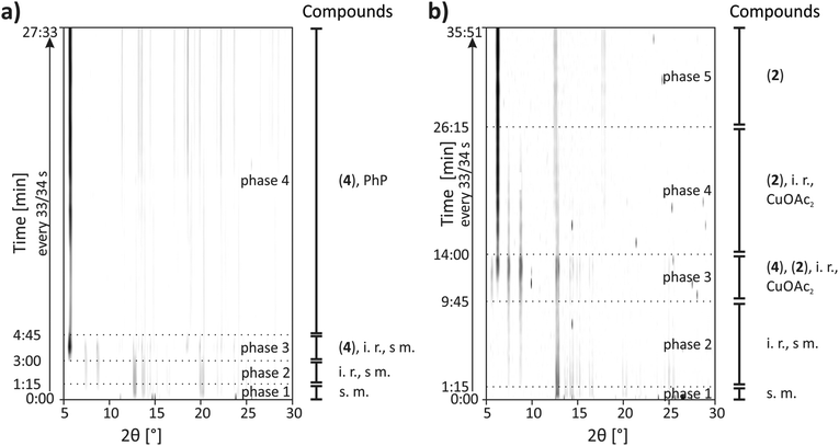
CuPhP2mH (4) can be easily obtained from mechanochemical synthesis. The reaction was investigated in situ by synchrotron PXRD. The synthesis conditions were the same as described in the Experimental section except that a Perspex jar was used. The 2D plot of the in situ investigation at 50 Hz is shown in Fig. 9a. At the beginning only reflections of both starting materials could be detected (copper(II) acetate: 2θ = 12.8°, 14.3°, 15.1° etc., phenylphosphonic acid: 2θ = 13.7°, 14.7°, 20.1° etc.) After 1.15 min two reflections of an unknown phase (2θ = 7.4° and 8.8°) appeared. Reflections for the product appeared after 3.00 min of milling time. The strongest reflection is the (200) at 5.6°. The reflections of the unknown intermediate and copper(II) acetate monohydrate could be detected until 4.45 min. Until the end of the reaction only reflections of the product and phenylphosphonic acid could be detected. The results show that there is an unknown intermediate, characterized by only two reflections. This compound could be detected intermediately for different mechanochemical syntheses with phenylphosphonic acid and a divalent metal acetate.23,25 It is most probable an isomorphic metal phenylphosphonate or a phenylphosphonic acid polymorph. Reflections of phenylphosphonic acid could be detected until the end because of its excess use.Although the composition of copper and phenylphosphonic acid is 1![[thin space (1/6-em)]](https://www.rsc.org/images/entities/char_2009.gif) :
:![[thin space (1/6-em)]](https://www.rsc.org/images/entities/char_2009.gif) 2 in this compound, it appears when the molar ratio of phenylphosphonic acid is three or four times higher than the one of copper(II) acetate monohydrate. The mechanochemical synthesis with the correct ratio of 1
2 in this compound, it appears when the molar ratio of phenylphosphonic acid is three or four times higher than the one of copper(II) acetate monohydrate. The mechanochemical synthesis with the correct ratio of 1![[thin space (1/6-em)]](https://www.rsc.org/images/entities/char_2009.gif) :
:![[thin space (1/6-em)]](https://www.rsc.org/images/entities/char_2009.gif) 2 results in a different product side by side with phenylphosphonic acid. This product is most probable β-CuPhPmH (2) as based on EXAFS and PXRD measurements, discussed in the ESI.† This product can be synthesized purely when the mechanochemical synthesis is done in a 1
2 results in a different product side by side with phenylphosphonic acid. This product is most probable β-CuPhPmH (2) as based on EXAFS and PXRD measurements, discussed in the ESI.† This product can be synthesized purely when the mechanochemical synthesis is done in a 1![[thin space (1/6-em)]](https://www.rsc.org/images/entities/char_2009.gif) :
:![[thin space (1/6-em)]](https://www.rsc.org/images/entities/char_2009.gif) 1 ratio of copper(II) acetate and phenylphosphonic acid.
1 ratio of copper(II) acetate and phenylphosphonic acid.
The milling synthesis of β-CuPhPmH (2) with a 1![[thin space (1/6-em)]](https://www.rsc.org/images/entities/char_2009.gif) :
:![[thin space (1/6-em)]](https://www.rsc.org/images/entities/char_2009.gif) 1 ratio of the starting materials was investigated by synchrotron PXRD ex situ at 50 Hz and in situ at 30 Hz and 50 Hz.
1 ratio of the starting materials was investigated by synchrotron PXRD ex situ at 50 Hz and in situ at 30 Hz and 50 Hz.
The 2D plot of the reaction at 30 Hz is shown in Fig. 8b. At the beginning only reflections of the starting materials can be detected. After 1.15 min milling time two reflections at 7.4° and 8.8° indicate the formation of the unknown intermediate. Reflections of phenylphosphonic acid persist until 6.30 min. The product reflections can be detected for the first time after 9.45 min (2θ = 6.2°, 12.5°, 17.8° etc.). Additionally, the strong reflection of CuPhP2mH (4) at 5.6° can be detected. It persists until 14.00 min of milling time. The reflections of the unknown intermediate and copper(II) acetate disappear after 26.15 min.
The in situ monitoring of the milling synthesis at 50 Hz leads to comparable results but the reaction is accelerated. The pure product could be detected after 3.15 min. Furthermore, there are no reflections of CuPhP2mH (4). A detailed description is given in the ESI (Fig. S15b†).
The resulting powder patterns of the ex situ monitoring of the synthesis of β-CuPhPmH (2) at 50 Hz are shown in Fig. S15a.† The reaction is finished after 7 min and the strong reflection at 5.6° of CuPhP2mH (4) appears intermediately.
It can be assumed, that CuPhP2mH (4) is an intermediate in the mechanochemical formation of β-CuPhPmH (2), based on the results of the ex situ investigation and the in situ investigation at 30 Hz. At 50 Hz it could not be detected. Probably, the reaction is just too fast for a crystallisation of CuPhP2mH (4) or the endurance of the intermediate is too short for the 30 s time resolution. The reaction time is different in all three investigations. The decrease of the frequency from 50 Hz to 30 Hz resulted in a pronounced decrease of the reaction speed. Instead of 3.15 min the reaction needed 26.15 min. These results support the diffusion mechanism, which could be observed earlier for this setup.23,24,40,41 The reaction time in the ex situ investigation at 50 Hz is longer than in the in situ investigation at 50 Hz. The milling process is stopped every 30 s which interrupted the reaction process and can result in a slower process. It is also possible that the waiting time between the removal of the sample and the measurement give the intermediate phases enough time to form as a crystalline compound.
The investigation of the mechanochemical synthesis of CuPhP2mH (4) did not succeed ex situ at 50 Hz and in situ at 30 Hz.
It was also possible to transform CuPhP2mH (4) in β-CuPhPmH (2) and vice versa by adding the respective starting material. A schematic overview of the obtained mechanochemical reaction pathways is depicted in Fig. 10.
Fig. 11 represents a schematic conclusion of the found stability relations in the investigated precipitation and mechanochemical reactions. For the precipitation from solution the stability increases in the order: unknown intermediate 1 < CuPhP2mH (4) < α-CuPhPmH (1) < β-CuPhPmH (2) < γ-CuPhPmH (3). Under mechanochemical conditions a similar order is found, but with another intermediate: intermediate 2 < CuPhP2mH (4) < β-CuPhPmH (2).
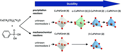 | ||
| Fig. 11 Scheme of the observed stabilities of the copper(II) phenylphosphonates in precipitation and mechanochemical reactions. | ||
Conclusions
We presented the synthesis of four copper(II) phenylphosphonates from solution at room temperature, elevated temperatures, under hydrothermal conditions, and from mechanochemical syntheses. The structures of three new phases were determined from PXRD and single X-ray analysis. Disorder of the crystal structures were clarified from single-crystal electron diffraction data.The reaction pathways for precipitation reactions at room temperature and mechanochemical reactions were investigated in situ. These results allowed estimation of the stability order of the compounds for both investigated reaction types.
Acknowledgements
The authors are grateful for the funding received by the DFG program “Crystalline non-equilibrium compounds” (grant number Em198/3-2). The authors thank Dr Andrea Zehl and Jenny Odoj (Department of Chemistry, Humboldt-Universität zu Berlin) for CHN analysis measurements.References
- A. Clearfield, Curr. Opin. Solid State Mater. Sci., 2002, 6, 495–506 CrossRef CAS.
- K. Maeda, Microporous Mesoporous Mater., 2004, 73, 47–55 CrossRef CAS.
- Y. P. Zhu, T. Y. Ma, Y. L. Liu, T. Z. Ren and Z. Y. Yuan, Inorg. Chem. Front., 2014, 1, 360–383 RSC.
- J. Goura and V. Chandrasekhar, Chem. Rev., 2015, 115, 6854–6965 CrossRef CAS PubMed.
- S. R. Batten, N. R. Champness, X. M. Chen, J. Garcia-Martinez, S. Kitagawa, L. Ohrstrom, M. O'Keeffe, M. P. Suh and J. Reedijk, Pure Appl. Chem., 2013, 85, 1715–1724 CrossRef CAS.
- E. Brunet, H. M. H. Alhendawi, C. Cerro, M. J. de la Mata, O. Juanes and J. C. Rodriguez-Ubis, Chem. Eng. J., 2010, 158, 333–344 CrossRef CAS.
- T. Y. Ma, X. Z. Lin, X. J. Zhang and Z. Y. Yuan, New J. Chem., 2010, 34, 1209–1216 RSC.
- R. Sen, D. Saha, D. Mal, P. Brandao, G. Rogez and Z. Lin, Eur. J. Inorg. Chem., 2013, 2013, 5020–5026 CAS.
- A. Dutta, A. K. Patra and A. Bhaumik, Microporous Mesoporous Mater., 2012, 155, 208–214 CrossRef CAS.
- G. Alberti, M. Casciola, R. Palombari and A. Peraio, Solid State Ionics, 1992, 58, 339–344 CrossRef CAS.
- R. M. P. Colodrero, P. Olivera-Pastor, A. Cabeza, M. Papadaki, K. D. Demadis and M. A. G. Aranda, Inorg. Chem., 2010, 49, 761–768 CrossRef CAS PubMed.
- M. Taddei, A. Donnadio, F. Costantino, R. Vivani and M. Casciola, Inorg. Chem., 2013, 52, 12131–12139 CrossRef CAS PubMed.
- A. Donnadio, M. Nocchetti, F. Costantino, M. Taddei, M. Casciola, F. D. Lisboa and R. Vivani, Inorg. Chem., 2014, 53, 13220–13226 CrossRef CAS PubMed.
- R. Thakkar and U. Chudasama, J. Iran. Chem. Soc., 2010, 7, 202–209 CrossRef CAS.
- P. H. Mutin, G. Guerrero and J. G. Alauzun, J. Ceram. Soc. Jpn., 2015, 123, 709–713 CrossRef CAS.
- B. Bujoli, P. Janvier and M. Petit, in Metal Phosphonate Chemistry: From Synthesis to Applications, The Royal Society of Chemistry, 2012, pp. 420–437, 10.1039/9781849733571-00420.
- G. Alberti, U. Costantino, S. Allulli and N. Tomassini, J. Inorg. Nucl. Chem., 1978, 40, 1113–1117 CrossRef CAS.
- D. Cunningham and P. J. D. Hennelly, Inorg. Chim. Acta, 1979, 37, 95–102 CrossRef CAS.
- G. Cao, H. Lee, V. M. Lynch and T. E. Mallouk, Inorg. Chem., 1988, 27, 2781–2785 CrossRef CAS.
- Y. P. Zhang and A. Clearfield, Inorg. Chem., 1992, 31, 2821–2826 CrossRef CAS.
- N. Stock and T. Bein, Angew. Chem., Int. Ed., 2004, 43, 749–752 CrossRef CAS PubMed.
- C. Bellitto, F. Federici, A. Altomare, R. Rizzi and S. A. Ibrahim, Inorg. Chem., 2000, 39, 1803–1808 CrossRef CAS PubMed.
- M. Wilke, A. G. Buzanich, U. Reinholz, K. Rademann and F. Emmerling, Dalton Trans., 2016, 45, 9460–9467 RSC.
- M. Wilke, L. Batzdorf, F. Fischer, K. Rademann and F. Emmerling, RSC Adv., 2016, 6, 36011–36019 RSC.
- L. Batzdorf, F. Fischer, M. Wilke, K. J. Wenzel and F. Emmerling, Angew. Chem., Int. Ed., 2015, 54, 1799–1802 CrossRef CAS PubMed.
- O. Paris, C. H. Li, S. Siegel, G. Weseloh, F. Emmerling, H. Riesemeier, A. Erko and P. Fratzl, J. Appl. Crystallogr., 2007, 40, S466–S470 CrossRef CAS.
- A. P. Hammersley, S. O. Svensson, M. Hanfland, A. N. Fitch and D. Hausermann, High Pressure Res., 1996, 14, 235–248 CrossRef.
- H. Riesemeier, K. Ecker, W. Gorner, B. R. Muller, M. Radtke and M. Krumrey, X-Ray Spectrom., 2005, 34, 160–163 CrossRef CAS.
- U. Kolb, T. Gorelik, C. Kubel, M. T. Otten and D. Hubert, Ultramicroscopy, 2007, 107, 507–513 CrossRef CAS PubMed.
- A. Altomare, C. Cuocci, C. Giacovazzo, A. Moliterni, R. Rizzi, N. Corriero and A. Falcicchio, J. Appl. Crystallogr., 2013, 46, 1231–1235 CrossRef CAS.
- G. M. Sheldrick, SHELXS-97, Program for the solution of crystal structures, Universität Göttingen, Göttingen, Germany, 1997 Search PubMed.
- G. M. Sheldrick, SHELXL-97, program for crystal structure refinement, Universität Göttingen, Göttingen, Germany, 1997 Search PubMed.
- W. I. F. David, K. Shankland, J. van de Streek, E. Pidcock, W. D. S. Motherwell and J. C. Cole, J. Appl. Crystallogr., 2006, 39, 910–915 CrossRef CAS.
- T. O. Salami, X. Fan, P. Y. Zavalij and S. R. J. Oliver, Dalton Trans., 2006, 1574–1578, 10.1039/b510942f.
- E. M. Bauer, C. Bellitto, G. Righini, M. Colapietro, G. Portalone, M. Drillon and P. Rabu, Inorg. Chem., 2008, 47, 10945–10952 CrossRef CAS PubMed.
- K. J. Martin, P. J. Squattrito and A. Clearfield, Inorg. Chim. Acta, 1989, 155, 7–9 CrossRef CAS.
- G. Cao, V. M. Lynch and L. N. Yacullo, Chem. Mater., 1993, 5, 1000–1006 CrossRef CAS.
- T. R. Welberry, Diffuse X-ray scattering and models of disorder, Oxford University Press, 2004 Search PubMed.
- C. D. Sherrill, T. Takatani and E. G. Hohenstein, J. Phys. Chem. A, 2009, 113, 10146–10159 CrossRef CAS PubMed.
- F. Fischer, G. Scholz, L. Batzdorf, M. Wilke and F. Emmerling, CrystEngComm, 2015, 17, 824–829 RSC.
- F. Fischer, A. Heidrich, S. Greiser, S. Benemann, K. Rademann and F. Emmerling, Cryst. Growth Des., 2016, 16, 1701–1707 CAS.
Footnote |
| † Electronic supplementary information (ESI) available. CCDC 1490687–1490689. For ESI and crystallographic data in CIF or other electronic format see DOI: 10.1039/c6dt02904c |
| This journal is © The Royal Society of Chemistry 2016 |

