
 Open Access Article
 This Open Access Article is licensed under a
 Creative Commons Attribution 3.0 Unported Licence
Complex shaped ZnO nano- and microstructure based polymer composites: mechanically stable and environmentally friendly coatings for potential antifouling applications†
Iris
Hölken
*a,
Mathias
Hoppe
a,
Yogendra K.
Mishra
*a,
Stanislav N.
Gorb
b,
Rainer
Adelung
a and
Martina J.
Baum
a
aFunctional Nanomaterials, Institute for Materials Science, Faculty of Engineering, University of Kiel, Kaiserstr. 2, D-24143, Kiel, Germany. E-mail: ih@tf.uni-kiel.de; ykm@tf.uni-kiel.de
bFunctional Morphology and Biomechanics, Zoological Institute, Department of Zoology, University of Kiel, Botanischen Garten 1–9, D - 24098 Kiel, Germany
First published on 3rd February 2016
Abstract
Since the prohibition of tributyltin (TBT)-based antifouling paints in 2008, the development of environmentally compatible and commercially realizable alternatives is a crucial issue. Cost effective fabrication of antifouling paints with desired physical and biocompatible features is simultaneously required and recent developments in the direction of inorganic nanomaterials could play a major role. In the present work, a solvent free polymer/particle-composite coating based on two component polythiourethane (PTU) and tetrapodal shaped ZnO (t-ZnO) nano- and microstructures has been synthesized and studied with respect to mechanical, chemical and biocompatibility properties. Furthermore, antifouling tests have been carried out in artificial seawater tanks. Four different PTU/t-ZnO composites with various t-ZnO filling fractions (0 wt%, 1 wt%, 5 wt%, 10 wt%) were prepared and the corresponding tensile, hardness, and pull-off test results revealed that the composite filled with 5 wt% t-ZnO exhibits the strongest mechanical properties. Surface free energy (SFE) studies using contact angle measurements showed that the SFE value decreases with an increase in t-ZnO filler amounts. The influence of t-ZnO on the polymerization reaction was confirmed by Fourier transform infrared-spectroscopy measurements and thermogravimetric analysis. The immersion tests demonstrated that fouling behavior of the PTU/t-ZnO composite with a 1 wt% t-ZnO filler has been decreased in comparison to pure PTU. The composite with a 5 wt% t-ZnO filler showed almost no biofouling.
1. Introduction
In the natural environment, all surfaces that are subjected to water become colonized by aquatic organisms, a process which is widely known as biofouling.1 This inevitable mechanism and the associated growth of sessile micro- and macroorganisms on any substrate has negative consequences for many technical applications, such as increasing surface roughness, mass gain or sometimes even biocorrosion.2 Especially in the shipping industry, the increased drag resistance and weight gain induced by the accumulation of organisms cause additional fuel consumption of up to 40% and consequential greenhouse gas emissions, as well as significantly increased transportation costs.3,4 Therefore it is very important to understand the biofouling mechanism under aquatic conditions and to develop appropriate antifouling coatings using versatile fabrication strategies.In general, aquatic biofouling can be considered as a four step process.5 The first step involves the biochemical conditioning, where van der Waals interactions initiate the formation of a conditioning film which mainly consists of organic molecules. Actually, this process instantaneously occurs on any surface which comes into contact with natural seawater. In the second step, the bacterial colonization takes place in which the bacteria and diatoms start to adhere to the surface and form a microbial biofilm. This biofilm which simultaneously acts as a source of nutrition is essential for the initiation of the third step, including the accumulation of unicellular eukaryotes like spores of macroalgae. The fourth and last step is assigned to the attachment of multicellular foulers, such as mollusks and barnacles. Unfortunately, this easy to describe process is dependent on many naturally occurring parameters such as, to name only a few, salinity, temperature, solar radiation or the interaction between a huge variety of organisms. From these naturally occurring parameters, it is obvious that simply the suppression of the conditioning film is not a straightforward solution, indeed one has to overcome many more issues and hence the biofouling community is in great need for developing new and suitable antifouling paints via robust approaches.4,5
The classical idea of antifouling paints is mainly based on the inclusion of biocidal additives to kill the fouling organisms, like bacteria, algae or barnacles.6 Tributyltin (TBT)-based coatings, the most effective products in this context, were developed during the 1980s and it was observed that they can strongly reduce biofouling and thereby reduce maintenance costs.7 However, earlier research has shown that these biocides strongly influence the marine environment to a critical extent, especially a significant impact on the embryogenesis of oysters was proven and hence TBT was classified as non-environmentally friendly.7 As a result, a global regulation was initiated in 2003 which prohibited the utilization of organic TBT-based coatings for marine applications.2,8 In the last few decades, several alternatives have been introduced including the usage of Cu- and Zn-compounds, self-polishing paints or silicone-based coatings, etc. as antifouling paints for underwater marine applications.
Actually the very first-mentioned solution is heavily criticized due to the fact that these paints still contain certain biocides which are harmful for the marine environment and are therefore under pending prohibition within the next years.9 Self-polishing paints can be a combination of harmful biocides and abrasive behavior of specific polymers; some others are based only on abrasion. However, it still remains unclarified whether the constituents of such ablating coating exhibit the desired compatibility with respect to the natural environment. The latter mentioned silicone-based antifouling solutions have been proven to be effective fouling release coatings due to their low surface energy and low elastic modulus, but they still lack the necessary requirements to be employed in mechanically affected areas, for example ship hulls.9 Actually silicone (PDMS) is unable to provide the necessary mechanical stability and the toxin-free solutions do not facilitate satisfactory antifouling characteristics. Thus the PDMS based coatings are technically inappropriate and there is an urgent demand for the development of new and innovative environmentally friendly and mechanically stable coatings with adequate antifouling properties. Modern antifouling paints are expected to withstand the rough environmental conditions like UV-irradiation, salinity, and high mechanical forces. Additionally, lifetimes of up to five years are desired, at the same time the fabrication steps for these coatings must be as simple as possible for implementation and realization up to industrial scales.
In order to meet the technical requirements for antifouling applications, the properties of the polymer based coatings need to be accordingly improved. This can easily be achieved by incorporating appropriate filler materials in the form of particles. The filler particles could be of any type, organic or inorganic, the only necessary criterion is that it must equip the resultant composite with desired properties.10,11 Nano- and microstructures from inorganic materials, particularly from metal oxides, have shown strong potential as they can enormously improve the properties of the resultant polymer composites. Since the size and shape of nanoscale fillers exhibit an important effect on the properties of polymer composites, the appropriate selection of filler particles is most crucial. Nano- and microscale particles with complex three dimensional (3D) geometries are preferable to spherical particles due to reduced agglomeration during synthesis and strong improvement in physical and chemical properties of the resulting composite.12 In the metal oxide family, zinc oxide (ZnO) is probably the most popular material for versatile nanostructuring and its nano- and microstructures exhibit multifunctional physical and chemical properties suitable for various applications.13,14 In the context of ZnO nanostructuring, the recently introduced flame transport synthesis (FTS) process offers simple and mass scale synthesis of tetrapodal shaped ZnO (t-ZnO) nano- and microstructures.10 In fact, t-ZnO based polymer composites are observed to exhibit improved mechanical properties, suitable for a wide range of applications.15,16
In addition to the manifold physical and chemical properties, these t-ZnO particles are also biocompatible.17 Hence with all these unique properties, they can be utilized as fillers for fabricating efficient coatings for antifouling applications and a first attempt has been made in this context using PTU as the matrix polymer.
In the present work, the development of an environmentally friendly and mechanically stable antifouling coatings using a novel solvent-free polyurethane-based composite system with a sulphur-containing polyol (polythiourethane, PTU) in combination with t-ZnO has been introduced for the first time to the best of our knowledge. PTU/t-ZnO composites with various t-ZnO filling fractions (wt%) have been synthesized and their mechanical, chemical, and physico-chemical properties have been thoroughly investigated. Varying stoichiometric polymer compositions, the influences of the morphology of filler particles and different amounts of t-ZnO fillers on the above properties have been studied in detail. Additionally only polymer/particle-variations were investigated, which have the potential for spraying application necessary for large scale applications like ship hulls. In order to determine the antifouling properties of the pure PTU polymer, as well as those of PTU/t-ZnO composites, preliminary immersion experiments were performed in the Aquarium at IFM Geomar, Kiel, Germany, and the observed results have been discussed.
2. Materials and methods
2.1 Polythiourethane
The two-component polythiourethane (PTU) thermoset used in this study was purchased from Fluid-& Prozesstechnik GmbH (Waltershausen, Germany). Detailed informations about the components hexamethylene diisocyanate (HDI) and pentaerythritol tetrakis(3-mercaptopropionate) (PETMP) is available in a previously published work.18The polyaddition reaction of the prepolymers via the four SH-groups of PETMP and the reactive terminal HDI groups (NCO) is initiated directly after mixing and ends up in the formation of the characteristic urethane-linkage.19 Typically, aromatic diisocyanates are used due to their relatively high reactivity and comparably low price.20 However, due to the lack of the benzene ring, aliphatic diisocyanates provide high impact resistance as well as non-yellowing features enabling better UV-stability, which make them very suitable materials for long-lasting applications under natural conditions.19 The utilized HDI belongs to the special group of aliphatic diisocyanates and therefore PTU provides a stable polymeric matrix making it more relevant for highly mechanically stressed coatings.
2.2 Polymer sample preparation and stoichiometric variations
A polymer was prepared by mixing 58% HDI with the remaining 42% of PETMP. The mixing was done by hand and totally degassed in a desiccator. For mechanical and chemical investigations, the polymer blends were cast into silicone moulds or spread onto substrates and cured at 85 °C for about 24 h. For latter investigations, the cast surface subjected to air was considered as the frontside whereas the surface subjected to the silicone mould was considered as the backside. For the immersion tests, the polyvinylchloride (PVC) plates of 40 mm × 80 mm were coated by a 300 μm thick layer and dried for one week at ambient temperature. Starting from the predefined mixing ratio, deviating stoichiometries were studied to evaluate the influence of the mixing ratio on the mechanical and chemical properties of the polymer. The stoichiometries between 30 and 75% HDI were mainly tested.2.3 Ceramic t-ZnO and s-ZnO as fillers
As already mentioned, zinc oxide, a wide bandgap semiconductor with a direct bandgap of ∼3.37 eV,21 has been widely used for multifunctional applications. Because of its hexagonal-wurtzite crystal structure, it offers a large possibility of synthesizing different types of nano- and microstructures.16,17 The morphology of the synthesized ZnO structures significantly depends on the manufacturing parameters and the utilized experimental techniques.22,23 Besides spherical (s-ZnO, Fig. 1b) or spring-like structures, three dimensional tetra needle shaped particles (t-ZnO) can be obtained.24 At the University of Kiel, recently a very simple and solvent free flame transport synthesis process has been introduced which allows versatile nanostructuring of ZnO including other metal oxides too.13,25 Most importantly, the developed FTS process allows mass scale production of different types of t-ZnO nano- and microstructures which can be used for large scale applications. The growth mechanism of ZnO tetrapods in the FTS process has already been described in detail in a previously published work.25 In the present work, FTS synthesized t-ZnO particles with a mean arm length of ∼20 μm (shown by the SEM image in Fig. 1a) have been used to fabricate the coatings. To investigate the influence of the particle’s morphology, spherical ZnO-particles (diameter ∼300 nm) were used as reference (Sigma Aldrich, Westerhausen, Germany). | ||
| Fig. 1 The polymer/particle-composites, the additives and their effects on the surface coatings. SEM micrographs of (a) tetrapodal and (b) spherical ZnO structures. Photographs of the coatings; (c) without particles, polymer/particle-composites with (d) 1 wt% t-ZnO, (e) 5 wt% t-ZnO, (f) 1 wt% s-ZnO, and (g) 5 wt% s-ZnO. | ||
2.4 Polymer/particle composites
Polymer/particle composites with varying amounts of ZnO fillers (0 wt%, 1 wt%, 5 wt%, 10 wt%) were produced and accordingly studied. To investigate the influence of the particle-morphology, t-ZnO and s-ZnO were comparatively evaluated. The appropriate amount of ZnO-particles was stirred in the PETMP-component and the mixture was homogenized by hand-stirring. Afterwards, an adequate amount of the HDI-component was added and the samples were prepared accordingly as described in the sample preparation procedure.2.5 Tensile experiments
Tensile tests were performed using a Zwick 1445 universal testing machine (Zwick GmbH und Co. KG, Ulm, Germany) equipped with a 10 kN load cell and a constant strain rate of 1 mm min−1 was applied. Dog-bone-shaped samples with a diameter of ∼1 mm, a width of ∼5 mm and a measuring length of ∼20 mm were prepared following the standard procedure. The mean values and the corresponding standard deviations were calculated from ten specimen datasets. Additionally, the data were statistically analyzed using the SigmaPlot 13.0 software (SPSS Inc., Chicago, USA). Significant differences between the investigated materials were carefully evaluated by the t-test (significance level: p < 0.03, normally and variance test were passed).2.6 Shore-D hardness measurements
For the hardness testing in accordance with Shore-D, rectangular samples of 20 mm edge length and 8 mm thickness were cast onto Teflon molds following the standard procedure. In order to provide planar surfaces, the samples were milled on both sides. The measurements were performed using a Zwick/Roell device (Zwick GmbH und Co. KG, Ulm, Germany) with a contact force of 50 N. The mean values and the corresponding standard deviations were calculated from ten readings.2.7 Pull-off tests
Pull-off tests were performed on rectangular AlMg3 substrates of dimensions 80 mm × 80 mm. The substrates were coated with the material to be analyzed and dried for 24 h, afterwards a cylindrical AlMg3 rod with a radius of 10 mm was glued in the middle of the sample using a UHU endfest 300 and hardened for 24 h at ambient temperature. The measurements were performed using a Zwick universal testing machine (Zwick GmbH und Co. KG, Ulm, Germany) at a pre-load of 30 N and a constant speed of 1 mm min−1. The mean values and standard deviations were extracted from five datasets.2.8 Fourier transform infrared spectroscopy (FT-IR) studies
To evaluate the quantitative polyaddition of HDI and PETMP, FTIR measurements were performed using a Bruker Tensor 29 system (Bruker, Bremen, Germany) on the polymer/composite variations.2.9 Thermogravimetric analysis (TGA)
The thermal decomposition of the PTU/t-ZnO composite materials was investigated using a TGA7 Thermogravimetric Analyzer (Perkin Elmer, Massachusetts, USA). Sample masses of about 2 mg were heated from 50 °C to 650 °C at a constant ramp rate of 10 °C min−1 inside a furnace with a constant nitrogen flow of 20 ml min−1. The differentiation of the degradation stages is based on the averaged mass loss measured on three polymer/composite variations.2.10 Contact angle and surface energy measurements
The influence of the particle amount (0 wt%, 1 wt%, 5 wt% t-ZnO) within PTU on the wetting behavior and free surface energy (FSE) of the coated surfaces was investigated in detail. The contact angle and the free surface energy were estimated using the high-speed optical contact angle measuring apparatus OCAH 200 (DataPhysics Instruments GmbH, Filderstadt, Germany). To evaluate these parameters and their components, contact angles of three defined liquids (water, diiodomethane, ethylene glycol with densities of 1.000 kg m−3, 3.325 kg m−3 and 1.113 kg m−3, respectively) were measured by the sessile drop method with a drop volume of 2 μl. For every polymer/composite combination, three samples were characterized and on each sample ten measurements were performed. The obtained datasets were statistically analyzed using the SigmaPlot 13.0 software (SPSS Inc., Chicago, USA). A one way ANOVA (p < 0.05) was followed by a pairwise multiple comparison procedure, the Holm–Sidak method (p < 0.05).The contact angles were evaluated by Young–Laplace fitting26 for calculations. The free surface energy was calculated by the universal method of Owens–Wendt–Rebel and Kaelble.27 The calculations of the contact angles and free surface energy were performed after Adamson (1982)26 and Owens and Wendt (1969)27 in accordance with Gorb & Gorb (2006).28
2.11 Immersion experiments
To test the antifouling capacity of the polymer/particle-composites, three specimens with different amounts of t-ZnO (0 wt%, 1 wt% and 5 wt%) were immersed in the “Pacific sea-tank” and the “Baltic sea-tank” of the Aquarium Geomar (Helmholtz Centre for Ocean Research, Kiel, Germany). PVC, as a well-known high-fouling polymer29,30 was immersed as reference31 for comparison. The experiment endured for 20 weeks at the “Pacific sea”-tank and for 30 weeks at the “Baltic sea”-tank, where the fouling process proceeded much slower. The status of fouling was inspected and recorded by digital photographs every week.3. Results and discussion
3.1 SEM morphologies of ZnO filler particles and fabricated PTU-ZnO coatings
The nano- and microscale t-ZnO structures, synthesized by the FTS process13 which is a solvent free approach, have been utilized as filler particles to fabricate antifouling coatings. In order to compare the performance, commercially purchased spherical ZnO nanoparticles were used as reference. The representative SEM morphologies of t-ZnO structures and reference ZnO nanoparticles are shown in Fig. 1a and b respectively. These tetrapods exhibit a 3D shape in the form of four arms tetragonally connected with a central core with an angle of ∼105° with respect to each other. Although the dimensions of these tetrapods span up to several microns their arms are still equipped with necessary nanoscale features. The 3D shape prohibits their close pack agglomerations (Fig. 1a) in contrast to spherical nanoparticles (Fig. 1b). Both particles (t-ZnO and s-ZnO) have been used as fillers in the PTU coatings and the effect of the filler particles on the surface coatings is shown in Fig. 1c–g. Visual appearances of coatings with both types of fillers at identical filling fractions (wt%) are almost the same but the physical and antifouling properties of PTU/t-ZnO coatings are superiorly improved as can be seen in the next sections.3.2 Tensile response and stoichiometric variations of fabricated composites
The influence of the stoichiometric variations of the chemical components on the stress–strain behavior of PTU was examined and is shown in Fig. 2. At the standard composition of 58% HDI, the tensile stress reached a maximum value of more than 60 MPa and the elongation at fracture reached almost 20%. The ultimate tensile strength of the material decreased drastically with a decreasing amount of HDI, the value declined to less than 10 MPa for 38% HDI whereby the elongation at fracture with more than 150% was more than seven times higher in comparison to that of the standard mixture. Fig. 2 illustrates the dependency of the ultimate tensile strength and the elongation at fracture on the amount of HDI. The HDI amount could be increased up to 70% before the ultimate tensile stress declined to lower values, however, the elongation at fracture was negligibly affected. A deviating behavior was observed for a decreasing amount of HDI where the ultimate tensile strength was decreased with an increase in the elongation at fracture. A comparable result was also obtained by Papaj et al. (2014),32 where the effect of hardener variations on the protective properties of a polyurethane coating was reported. It was observed that deviations from the predefined component ratio and therefore compositions differing from the 100% stoichiometric composition, where no unreacted functional groups are present, have a strong influence on the mechanical and chemical properties. These results are in good compliance with those obtained for the stoichiometric variations of the PTU investigated here.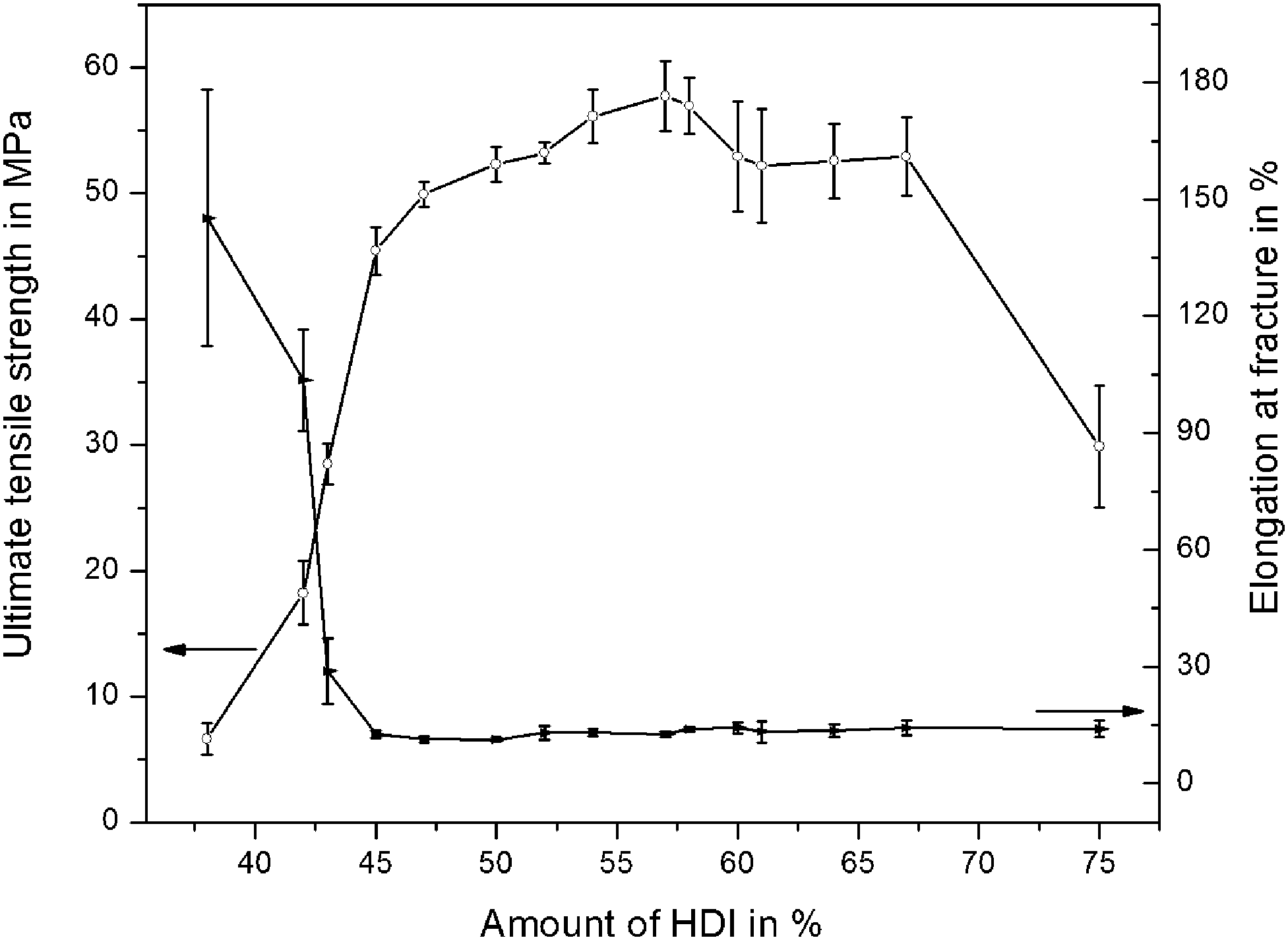 | ||
| Fig. 2 Influence of HDI-content on ultimate tensile strength and elongation at fracture of PTU. Mean values and standard deviations are shown. | ||
3.3 Mechanical characteristics of polymer/particle-composites
The influence of differently shaped ZnO-particles (t-ZnO and s-ZnO) on the mechanical properties of the polymeric matrix was investigated by tensile testing, pull-off test and Shore-D hardness for three different amounts of fillers for each of the two different shapes; tetrapodal (Fig. 1a) and spherical (Fig. 1b). The comparison of the obtained values is given in Table 1 (Fig. S1, ESI†), which clearly demonstrates that the filler amount of 5 wt% significantly improved the mechanical properties. The Shore-D hardness was increased from initially 71.1% (pure PTU) up to 81% for a filler amount of 5 wt%. The tensile strength was slightly increased and the adhesion to AlMg3 was more than doubled from 0.26 MPa up to 0.64 MPa. Slightly decreased values were obtained for the elastic modulus and the elongation at fracture.| Polymer & amount of particles | PTU none | PTU 1 wt% t-ZnO | PTU 5 wt% t-ZnO | PTU 10 wt% t-ZnO | PTU 1 wt% s-ZnO | PTU 5 wt% s-ZnO | PTU 10 wt% s-ZnO |
|---|---|---|---|---|---|---|---|
| Shore D | 75.1 ± 3.3 | 76.0 ± 2.5 | 81.0 ± 1.6 | 79.8 ± 3.0 | 77.0 ± 3.1 | 75.2 ± 2.4 | 75.9 ± 2.1 |
| E-modulus (MPa) | 981.5 ± 74.7 | 895.5 ± 49.7 | 952.5 ± 83.0 | 997.0 ± 75.1 | 967.0 ± 64.9 | 990.0 ± 98.0 | 952.0 ± 96.5 |
| Tensile strength (MPa) | 57.1 ± 0.4 | 56.6 ± 0.7 | 58.7 ± 1.4 | 55.0 ± 1.7 | 54.6 ± 0.5 | 54.1 ± 0.6 | 55.6 ± 0.4 |
| Elongation at fracture (%) | 15.4 ± 1.4 | 14.5 ± 0.9 | 12.1 ± 0.5 | 10.7 ± 0.2 | 23.0 ± 2.2 | 18.2 ± 1.9 | 18.0 ± 1.2 |
| Adhesion on AlMg3 (MPa) | 0.26 ± 0.01 | 0.50 ± 0.03 | 0.64 ± 0.04 | 0.63 ± 0.04 | 0.28 ± 0.01 | 0.26 ± 0.01 | 0.28 ± 0.01 |
Almost similar results have been reported for the enhancement of resin composites by the addition of tetrapod-like zinc oxide whiskers.15 It was demonstrated that the tensile strength was significantly higher for samples containing 5 wt% t-ZnO compared with those of the other polymer/particle variations (0 wt%, 5 wt%, 10 wt% filler amounts), whereas the elongation at fracture showed a slight decrease for t-ZnO and an increase for s-ZnO fillers. It was declared for t-ZnO in dental resins that the revealed reinforcement is a result of the prevention of crack propagation due to the tetrapodal shaped particle structure pointing in four different directions.33 Besides this, Niu et al. (2010)15 ascribed the decrease in mechanical strength for filler amounts higher than 5 wt% to particle agglomerations or increasing amounts of air-bubbles incorporated into the polymer/particle-composites. The increase in adhesion strength can be explained by interlocking mechanisms between the tetrapods and the surface of the substrate. As this effect could not be seen for spherical particles, it can be assumed that the introduced changes in properties are mainly due to the special three-dimensional particle morphology.
3.4 FT-IR spectroscopy of the polymer/particle-composites
To investigate the influence of the particles on the quantitative polyaddition of HDI and PETMP, FT-IR spectroscopy was performed as shown in Fig. 3. For incomplete reactions a S–H vibration from PETMP at 2545 cm−1 or an –NCO peak from HDI at 2272 cm−1 would be expected.18 The lack of these absorption peaks is an indicator that t-ZnO has no influence on the completeness of the reaction.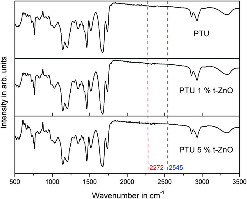 | ||
| Fig. 3 FT-IR spectra of the polymer/composites with varying filler amounts. | ||
3.5 Thermogravimetric analysis
The influence of the particles on the decomposition temperature of the composite was investigated by thermogravimetric analysis (Fig. S2, ESI†). Detailed information on the thermal decomposition of polyurethanes can be found in the work by Chattopadhyay and Webster 200934 where it is shown that the thermal degradation of PU usually involves three steps which can be attributed to the hard and soft segments of the polymer. These steps were also found during the decomposition of the samples investigated in this work; nevertheless, the decomposition temperature was not influenced by the particles. The first average decomposition started at 306 °C ± 10.12 °C followed by the average second decomposition at 371 °C ± 6.08 °C and the third average decomposition at 520 °C ± 5.00 °C (Fig. S2, ESI†).3.6 Contact angle, surface energy measurements and immersion results
The results for the water contact angle measurements and the calculated free surface energy (FSE) with its polar and dispersive parts are given in Table 2. The antifouling properties were evaluated by immersion tests. For this purpose, the polymer/particle-variations with different t-ZnO filler amounts were prepared with respect to the obtained material characteristics. The composite with 5 wt% t-ZnO was chosen as the highest amount to be tested. Higher amounts (>5 wt%) are unsuitable for the intended objective particularly because the increased viscosity prohibits spray application, which is an essential criterion for the application on large scale marine buildings.| Sample | CA | FSE (mJ m−2) | Pol. (mJ m−2) | Disp. (mJ m−2) | ra (μm) | Data source |
|---|---|---|---|---|---|---|
| PTU 0 wt% t-ZnO | 67.4 ± 3.4 | 40.7 ± 0.5 | 12.4 ± 1.7 | 28.4 ± 1.2 | 0.037 | Present work |
| PTU 1 wt% t-ZnO | 70.4 ± 3.7 | 39.9 ± 0.8 | 10.0 ± 2.3 | 29.8 ± 1.7 | 0.012 | Present work |
| PTU 5 wt% t-ZnO | 72.8 ± 3.3 | 37.4 ±1.6 | 9.2 ± 1.0 | 28.2 ± 1.3 | 0.042 | Present work |
| Polyvinylchloride – PVC | 73.5 ± 1.7 | 46.0 | 5.0 | 41.0 | — | 37, 40 |
| Polydimethyl-siloxane – PDMS | 113.5 ± 2.0 | 18.8 | 3.6 | 15.2 | — | 38, 39 |
| Polytetrafluoro-ethylene – PTFE | 110.0 ± 4.0 | 23.0 | 1.0 | 22.0 | — | 37 |
To put the values of the free surface energy of the polymers also used for immersion tests into proportion, the free surface energy of well-known high- (PVC) and low-fouling (PDMS and PTFE) polymers from the literature (Table 2) was used.
The evaluation of water contact angle and free surface energy revealed a significant difference for the different kinds of polymer/particle-variations. A particle amount of 5 wt% t-ZnO compared to none resulted in an increased water contact angle (from 67.4° to 72.8°) and reduced free surface energy (from 40.7 to 37.4 mJ m−2), compared to pure PTU. An influence of surface roughness on the contact angle was excluded, because there was only a slight variation of this parameter between the different amounts of filling particles. When going into detail about the specific physical parameters influencing the contact angle and the free surface energy, we noticed a decrease within the polar fraction with an increasing filler amount and the corresponding values are given in Table 2. A decrease in the polar fraction of the polymer results in reduced physical interactions between the surface and the polar water molecules, therefore the attractive forces between liquid and solid phase decrease and the contact angle increases.
In order to verify the assumption that reduced FSE and with it a reduced polar fraction influence the antifouling properties of those polymer/particle-variations immersion experiments in the “Pacific”- and “Baltic sea”-tanks of the Aquarium Geomar were performed (Fig. 4). These experiments showed differences in antifouling properties of the four investigated polymer surfaces (PVC, PTU, PTU with 1 wt% t-ZnO, PTU with 5 wt% t-ZnO). For the “Pacific” and “Baltic sea”-environment, there was a strong reduction in the presence of fouling organisms on the polymer composite with 5 wt% of t-ZnO (Fig. 4a and e). This kind of polymer/particle-composite immersed in the “Pacific” and “Baltic sea”-environment was colonized by microorganisms like bacteria, diatoms and only loosely attached microalgae. No calcareous fouling organisms were found. The immersion test in the “Pacific”-environment for the PTU with a mid range particle amount of 1 wt% t-ZnO showed distinct growth of sessile marine organisms, but compared with pure PTU the fouling was strongly reduced as can be seen in Fig. 4b and c. In addition to the microorganisms found on the polymer composite with 5 wt% of t-ZnO on these kinds of composite polymers (PTU without particles and PTU with 1 wt% t-ZnO) visible algae were attached to the surface and invertebrates like anemones and tube worms were present, but the density of growth on the particle containing a polymer surface was much strongly reduced compared to the polymer without t-ZnO-particles. The uncoated PVC surfaces (Fig. 4d) showed fouling comparable to the PTU with 1 wt% t-ZnO immersed within the “Pacific” habitat, but dominated by a greater diversity of fouling species, than the surface of the 1 wt% t-ZnO–PTU composite.
 | ||
| Fig. 4 Preliminary experimental study on three variations of PTU containing (a) and (e) 5 wt% t-ZnO, (b) and (f) 1 wt% t-ZnO and (c) and (g) 0 wt% t-ZnO, (d) and (h) PVC as reference material. Surfaces (a)–(d) were immersed for 20 weeks in the “Pacific sea-tank” at the Aquarium Geomar. Surfaces (e)–(h) were immersed for 30 weeks in the “Baltic sea”-tank at the Aquarium Geomar. | ||
Almost no difference in the abundance of adhering marine organisms was found on polymer surfaces containing 1 wt% and 0 wt% t-ZnO (Fig. 4f and g) exposed to the “Baltic sea”-habitat, the fouling on both surfaces was mainly dominated by algae connected to the surface. Despite this finding, the PVC surface (Fig. 4h) exposed to the “Baltic sea”-environment showed the presence of similar fouling organisms like that on pure PTU and PTU with 1 wt% t-ZnO. The density of growth was strongly reduced, but not as reduced as found on PTU with 5 wt% t-ZnO exposed to the same environmental conditions as revealed in Fig. 4e.
The fouling process for the polymer/particle-composite and the PVC surface immersed in the “Pacific sea-tank” at the Aquarium Geomar (Fig. 5) showed at the beginning a continuous increase in growth for all surfaces until approximately week six but in varying degrees of severities. For the coatings containing 5 wt% and 1 wt% of t-ZnO, the maximum presence of fouling organisms was observed around 8th and 9th week followed by a slight decrease in fouling and a constant state of reduced adhering marine organisms for the remaining time of the experiment. Almost a continuous increase in the amount of adhering organisms on the polymer surfaces occurred on PTU containing no t-ZnO particles and on the uncoated PVC surface. After reaching an individual maximum biofouling density, the growth on these surfaces stayed almost constant for the remaining time of the experiment. It has to be pointed out that the fouling on PTU with 5 wt% t-ZnO never exceeded the fouling state of microfouling, meaning no algae or invertebrate were tightly attached to this kind of polymer surface, even when the degree of microfouling was varying within the time period of the experiment. A clear hint to reduced adhesion of microfouling organisms to this kind of surface was the observation that the thin microalgae film/biofilm can be easily removed just by repeated immersion of the polymer to the aqueous environment (Fig. 6). The assumption, that the overall reduced fouling on these kinds of surfaces is due to reduced adhesion to marine organisms, is also supported by the work of Chen et al. (2008)35 and Holland et al. (2004),36 who reported that the reduced free surface energy is beneficial to reduce biofouling on silicone elastomer surfaces. Even if the attachment of aquatic organisms cannot be prevented, it offers the possibility of the overall reduction of biofouling because of organism’s detachment due to reduced adhesion. However, the free surface energy of PTU with 5 wt% t-ZnO (37.4 mJ m−2) is not as low as stated for typical “easy-to-clean”-surfaces, like silicone or PTFE (18.8 mJ m−2 and 23.0 mJ m−2, respectively37–39), but is definitely less than that of other polymers like PVC (46.0 mJ m−2![[thin space (1/6-em)]](https://www.rsc.org/images/entities/char_2009.gif) 37,40). A detailed consideration of the phenomena of surface energy in context with biofouling opens up the question of the importance of the contribution of the polar fraction to the free surface energy and its effect on the phenomena of bioadhesion within an aqueous and therefore strongly polar environment. It can be assumed that variations in the polar fraction of the solid material (polymer surface) have a strong influence on the wetting behavior in general and on contact angle hysteresis in specific. This approach to find an explanation for the varying degrees of biofouling on different artificial surfaces has already been introduced by Schmidt et al. 200441 and their findings suggest that the fouling behavior of surfaces does not, as proposed by e.g., Baier, 2006,42 solely depend on the free surface energy, but also on contact angle hysteresis as it was stated that the growth is the lowest for surfaces with the lowest contact angle hysteresis. Contact angle hysteresis can be influenced by surface heterogeneity and therefore local variations in adhesion behavior.43 The detailed investigation of this parameter and its implications on biofouling is still under progress and will be part of future research. The previously developed antifouling coatings are mostly based on the macrofouling-releasing silicone-systems,36 surface-energy adjustment44 or biomimetic topographies like e.g., shark-skin45 and these approaches suffer from several drawbacks like, for example, low mechanical stability, unpredictability of environmental consequences or difficulties in practicability with respect to large scale application. In contrast to this, our complex shaped ZnO nano- and microstructure based polymer antifouling coatings have got several advantages in terms of fabrication simplicities, improved properties, enhanced performances, cost-effective productions etc. and hence offer a new and interesting perspective in the direction of biofouling applications.
37,40). A detailed consideration of the phenomena of surface energy in context with biofouling opens up the question of the importance of the contribution of the polar fraction to the free surface energy and its effect on the phenomena of bioadhesion within an aqueous and therefore strongly polar environment. It can be assumed that variations in the polar fraction of the solid material (polymer surface) have a strong influence on the wetting behavior in general and on contact angle hysteresis in specific. This approach to find an explanation for the varying degrees of biofouling on different artificial surfaces has already been introduced by Schmidt et al. 200441 and their findings suggest that the fouling behavior of surfaces does not, as proposed by e.g., Baier, 2006,42 solely depend on the free surface energy, but also on contact angle hysteresis as it was stated that the growth is the lowest for surfaces with the lowest contact angle hysteresis. Contact angle hysteresis can be influenced by surface heterogeneity and therefore local variations in adhesion behavior.43 The detailed investigation of this parameter and its implications on biofouling is still under progress and will be part of future research. The previously developed antifouling coatings are mostly based on the macrofouling-releasing silicone-systems,36 surface-energy adjustment44 or biomimetic topographies like e.g., shark-skin45 and these approaches suffer from several drawbacks like, for example, low mechanical stability, unpredictability of environmental consequences or difficulties in practicability with respect to large scale application. In contrast to this, our complex shaped ZnO nano- and microstructure based polymer antifouling coatings have got several advantages in terms of fabrication simplicities, improved properties, enhanced performances, cost-effective productions etc. and hence offer a new and interesting perspective in the direction of biofouling applications.
 | ||
| Fig. 5 Exemplary time sections from the preliminary immersion tests of three different polymer/particle-composites and thePVC surface as high fouling reference exposed to the “Pacific sea-tank” at the Aquarium Geomar. After three weeks slight biofouling is noticeable. Until week six continuous growth occurred on all surfaces, but in varying degrees of severity. Between week six to eleven the growth behavior varied between the different polymer surfaces. From week eleven until the end of the experiment after 20 weeks the amount of adhering marine organisms was almost constant on all surfaces. | ||
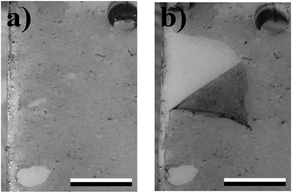 | ||
| Fig. 6 Reduced adhesion of the organic film, in contact with PTU containing 5 wt% t-ZnO subjected for seven weeks to artificial “Pacific”-environmental conditions at the Aquarium Geomar. (a) Before repeated immersion in water and (b) after repeated immersion in water (scale bar: 1 cm). | ||
4. Conclusions
The present study demonstrates the fabrication of a novel environmentally friendly polyurethane-based composite coating which is assumed to offer long lifetimes due to its high overall mechanical strength as well as adequate antifouling properties introduced by embedded flexible tetrapodal shaped ZnO (t-ZnO) nano- and microparticles. Additionally, it provides the ease for large-scale application as it is sprayable. In this work, the mechanical and chemical characterization of a novel two-component polythiourethane (PTU) system in combination with tetrapodal shaped ZnO as filler particles was performed and a preliminary study on the antifouling properties of this polymer/particle-composite was carried out. The observed results suggest that the PTU with an amount of 5 wt% t-ZnO exhibits convincing mechanical response (strong enough) as well as promising antifouling properties. Therefore, based on the observations, the introduced polymer/particle-composite is a very good starting point for the development of mechanically robust coatings for maritime structures and other related applications. However, field experiments further need to be conducted to verify the qualification of the composite material presented as mechanically stable, environmentally friendly and long-lasting antifouling paint.Acknowledgements
The authors are thankful to the Aquarium Geomar at Geomar – Helmholtz Centre for Ocean Research Kiel (Germany) for getting the opportunity to conduct the immersion test at their infrastructure and to Elena V. Gorb for technical support while using the contact angle measuring device. This work was funded within the projects DKL-WEA, “Nano-based coating technologies for erosion protection and de-icing of offshore-wind energy plants” and Nano-WWZ, “Coating technologies for the application of nano-based antifouling coatings in the water transition-zone of stationary maritime structures” by the Federal ministry for Economic Affairs and Energy.References
- S. Dobretsov, M. Teplitski and V. Paul, Biofouling, 2009, 25, 413–427 CrossRef CAS PubMed.
- A. Rosenhahn, S. Schilp, H. J. Kreuzer and M. Grunze, Phys. Chem. Chem. Phys., 2010, 12, 4275–4286 RSC.
- D. Carteau, K. Vallée-Réhel, I. Linossier, F. Quiniou, R. Davy, C. Compère, M. Delbury and F. Faÿ, Prog. Org. Coat., 2013, 77, 485–493 CrossRef.
- D. M. Yebra, S. Kiil and K. Dam-Johansen, Prog. Org. Coat., 2004, 50, 75–104 CrossRef CAS.
- M. Wahl, Mar. Ecol.: Prog. Ser., 1989, 58, 175–189 CrossRef.
- J. E. Gittens, T. J. Smith, R. Suleiman and R. Akid, Biotechnol. Adv., 2013, 31, 1738–1753 CrossRef CAS PubMed.
- R. S. Peres, E. Armelin, C. Aleman and C. A. Ferreira, Ind. Crops Prod., 2014, 65, 506–514 CrossRef.
- Y. Yonehara, H. Yamashita, C. Kawamura and K. Itoh, Prog. Org. Coat., 2001, 42, 150–158 CrossRef CAS.
- M. Wiegemann and B. Watermann, Rostock. Meeresbiolog. Beitrag, 2002, 11, 39–55 Search PubMed.
- F. Hussain, M. Hojjati, M. Okamoto and R. E. Gorga, J. Compos. Mater., 2006, 40, 1511–1575 CrossRef CAS.
- D. K. Chattopadhyay and K. V. S. N. Raju, Prog. Polym. Sci., 2007, 32, 352–418 CrossRef CAS.
- C. Wan, H. Tan, S. Jin, H. Yang, M. Tang and J. He, Mater. Sci. Eng., B, 2008, 150, 203–207 CrossRef CAS.
- Y. K. Mishra, S. Kaps, A. Schuchardt, I. Paulowicz, X. Jin, D. Gedamu, S. Freitag, M. Claus, S. Wille, A. Kovalev, S. N. Gorb and R. Adelung, Part. Part. Syst. Charact., 2013, 30(9), 775–783 CrossRef CAS.
- Z. L. Wang, Mater. Today, 2007, 7, 26–33 CrossRef.
- L. N. Niu, M. Fang, K. Jiao, L. H. Tang, Y. H. Xiao, L. J. Shen and J. H. Chen, J. Dent. Res., 2010, 89(7), 746–750 CrossRef CAS PubMed.
- X. Jin, M. Götz, S. Wille, Y. K. Mishra, R. Adelung and C. Zollfrank, Adv. Mater., 2013, 25(9), 1342–1347 CrossRef CAS PubMed.
- H. Papavlassopoulos, Y. K. Mishra, S. Kaps, I. Paulowicz, R. Abdelaziz, M. Elbahri, E. Maser, R. Adelung and C. Röhl, PLoS One, 2014, 9(1), e84983 Search PubMed.
- K. Strzelec, N. Baczek, S. Ostrowska, K. Wasikowska, M. I. Szynkowska and J. Grams, C. R. Chim., 2012, 15, 1065–1071 CrossRef CAS.
- I. Clemitson, Castable Polyurethane Elastomers, CRC Press, 2008 Search PubMed.
- G. W. Becker and D. Braun, Kunststoff Handbuch Polyurethane, Carl Hanser Verlag Muenchen Wien, 1993 Search PubMed.
- T. Charinpanitkul, P. Nartpochananon, T. Satitpitakun, J. Wilcox, T. Seto and Y. Otani, J. Ind. Eng. Chem., 2012, 18, 469–473 CrossRef CAS.
- Y. Wang, J. Shi, L. Han and F. Xiang, Mater. Sci. Eng., A, 2009, 501, 220–228 CrossRef.
- Z. L. Wang, J. Phys.: Condens. Matter, 2004, 16, 829–858 CrossRef.
- C. Ronning, N. G. Shang, H. Gerhards, H. Hofsäss and M. Seibt, J. Appl. Phys., 2005, 98(3), 34307 CrossRef.
- Y. K. Mishra, G. Modi, V. Cretu, V. Postica, O. Lupan, T. Reimer, I. Paulowicz, V. Hrkac, W. Benecke, L. Kienle and R. Adelung, ACS Appl. Mater. Interfaces, 2015, 7(26), 14303–14316 CAS.
- A. W. Adamson, Physical chemistry of surfaces, Wiley, New York, 1982 Search PubMed.
- D. Owens and R. Wendt, J. Appl. Polym. Sci., 1969, 13, 1741–1747 CrossRef CAS.
- E. Gorb and S. Gorb, Plant Biol., 2006, 8, 841–848 CrossRef CAS PubMed.
- W. P. Zhang, Y. Wang, R. M. Tian, S. Bougouffa, B. Yang, H. L. Cao, G. Zhang, Y. H. Wong, Z. Batang, A. Al-Suweilem, X. X. Zhang and P.-Y. Qian, Sci. Rep., 2014, 4, 6647 CrossRef CAS PubMed.
- O. O. Lee, W. Yong, R. Tian, W. Zhang, C. S. Shek, S. Bougouffa, A. Al-Suweilem, Z. B. Batang, W. Xu, G. C. Wang, X. Zhang, F. F. Lafi, V. B. Bajic and P.-Y. Qian, Sci. Rep., 2014, 4, 3587 Search PubMed.
- R. Oliveira, J. Azeredo and P. Teixeira, Bioline, 2001, 11–22 Search PubMed.
- E. A. Papaj, D. J. Mills and S. S. Jamali, Prog. Org. Coat., 2014, 77, 2086–2090 CrossRef CAS.
- H. H. Xu, T. A. Martin, D. T. Smith, J. M. Antonucci, G. E. Schumacher and F. C. Eichmiller, Biomaterials, 2002, 23, 735–742 CrossRef CAS PubMed.
- D. K. Chattopadhyay and D. C. Webster, Prog. Polym. Sci., 2009, 34, 1068–1133 CrossRef CAS.
- M. Chen, Y. Qu, L. Yang and H. Gao, Sci. China, Ser. B: Chem., 2008, 51, 848–852 CrossRef CAS.
- R. Holland, T. M. Dugdale, R. Wetherbee, A. B. Brennan, J. A. Finlay, J. A. Callow and M. E. Callow, Biofouling, 2004, 20(6), 323–329 CrossRef CAS PubMed.
- J. Van Dijk, F. Herkströter, H. Busscher, A. Weerkamp, H. Jansen and J. Arends, J. Clin. Periodontol., 1986, 14(5), 300–304 CrossRef.
- A. Mata, A. J. Fleischman and S. Roy, Biomed. Microdevices, 2005, 7(1), 281–293 CrossRef CAS PubMed.
- M. K. Chaudhury, J. Adhes. Sci. Technol., 1993, 7(6), 669–675 CrossRef CAS.
- M. Camps, A. Barani, G. Gregori, A. Bouchez, B. Le Berre, C. Bressny, Y. Blache and J.-F. Briand, Appl. Environ. Microbiol., 2014, 80, 4821–4831 CrossRef PubMed.
- D. L. Schmidt, R. F. Brady, K. Lam, D. C. Schmidt and M. K. Chaudhury, Langmuir, 2004, 20(7), 2830–2836 CrossRef CAS PubMed.
- R. E. Baier, J. Mater. Sci.: Mater. Med., 2006, 17, 1057–1062 CrossRef CAS PubMed.
- Y. Yuan and T. R. Lee, Surface science techniques, Springer, 2013, pp. 3–34 Search PubMed.
- L. K. Ista, M. E. Callow, J. A. Finlay, S. E. Coleman, A. C. Nolasco, R. H. Simons, J. A. Callow and G. P. Lopez, Appl. Environ. Microbiol., 2004, 70(7), 4151–4157 CrossRef CAS PubMed.
- A. J. Scardino and R. de Nys, Biofouling, 2011, 27(1), 73–86 CrossRef CAS PubMed.
Footnote |
| † Electronic supplementary information (ESI) available. See DOI: 10.1039/c5cp07451g |
| This journal is © the Owner Societies 2016 |