 Open Access Article
Efficient approach to iron/nitrogen co-doped graphene materials as efficient electrochemical catalysts for the oxygen reduction reaction†
Qingqing
Dong‡
ab,
Xiaodong
Zhuang‡
b,
Zhi
Li
*a,
Bin
Li
*a,
Bin
Fang
a,
Cunzhong
Yang
a,
Haifen
Xie
a,
Fan
Zhang
*b and
Xinliang
Feng
bc
aSchool of Mechanical and Power Engineering, Institute of Nuclear Technology and Application, East China University of Science and Technology, Shanghai, 200237, China. E-mail: lizhi69@yeah.net; binlee@ecust.edu.cn
bSchool of Chemistry and Chemical Engineering, Shanghai Jiao Tong University, 800 Dongchuan Road, Shanghai 200240, China. E-mail: fan-zhang@sjtu.edu.cn
cTechnische Universitaet Dresden, 01062 Dresden, Germany
First published on 16th February 2015
Abstract
Cyclopentadienyliron (CpFe) groups have been successfully attached on the surface of reduced graphene oxide (rG) by a ligand-exchange reaction of ferrocene (Cp2Fe) and rG to produce CpFe-modified reduced graphene oxide (rGFeCp), which exhibits good processability in many organic solvents. In a similar one-pot reaction, graphite was efficiently exfoliated using Cp2Fe as the intercalator to form CpFe-attached free-standing graphene nanosheets (GFeCp, ∼10 layers). Upon pyrolysis and ammonia activation, rGFeCp and GFeCp were converted to iron/nitrogen co-doped porous graphenes, namely, rGFe-800a and GFe-800a, respectively. The obtained rGFe-800a exhibited good electrochemical performance for the oxygen reduction reaction (ORR) under alkaline conditions (0.1 M KOH) with a low half-wave potential at −0.29 V, a dominant four-electron transfer mechanism (n = 3.5 at −1.0 V), and a maximum diffusion-limiting current density of 4.86 mA cm−2. In addition, rGFe-800a showed excellent methanol tolerance, superior to that of commercial 20% Pt/C. The effect of iron/nitrogen co-doping plays a key role in the good ORR activities of the as-prepared materials.
Introduction
Graphene, since its discovery in 2004, has attracted an enormous interest due to its desirable properties and broad potential applications in many fields.1 Its single-layer two-dimensional structure accompanied with its high surface area render it suitable for building nanostructured hybrid materials.2,3 In particular, the worldwide consciousness of the need for a sustainable low-carbon economy greatly promotes the development of new graphene-based energetic materials.4–7 The electrochemically catalyzed oxygen reduction reaction (ORR) is an important process in fuel cells and metal–air batteries.8,9 Because platinum-based materials have the highest catalytic activities for oxygen reduction among most of the pure metals supported on conductive carbon, they serve as the state-of-art cathode materials in low-temperature fuel cells.10,11 However, the large-scale production of these types of precious metal-containing catalysts is impossible because of the high price and scarcity of Pt.12 In addition, Pt-based catalysts are unfavorable for endurance tests due to their sensitivity to CO and methanol. Therefore, finding an inexpensive material to replace platinum is extremely important for the widespread application of fuel cells.13 In this aspect, heteroatom-doped (such as S, P and N) graphenes possess several potential advantages. Typically, nitrogen has proven to be an efficient dopant to greatly improve the activity and stability of graphene-based ORR catalysts,14 through creating electrically non-neutral sites on the graphene surface.15–19 A variety of non-noble metal compounds, such as transition-metal oxides/chalcogenides,20,21 have also been used to form metal-doped graphene composites; these compounds exhibit very good electrochemical performance in ORR catalysis22 because they can serve as separators for tuning the interplanar spacing of the neighboring graphene sheets, essentially allowing both sides of each graphene sheet to be accessible to the electrolyte. Although the uniform functionalization of carbon black or carbon nanotubes with transition metals (e.g. Fe) is found to be extremely successful, the functionalization of graphene is still a great challenge due to the limited preparation strategies.23–27Our present task focused on exploring new methods for efficiently codoping heteroatoms and transition metals in graphene. Given that reduced graphene oxide (rG) is one of the most easily-available derivatives of graphene, featuring good conductivity and a large specific surface area, herein we report a new synthetic method for the formation of cyclopentadienyliron (CpFe) modified rG (rGFeCp) and CpFe modified few-layer graphene nanosheets (GFeCp) by convenient ligand-exchange reactions of ferrocene with rG and graphite, respectively. The as-prepared rGFeCp and GFeCp were further pyrolyzed under nitrogen and activated under ammonia at different temperatures to produce a series of graphene composites with high nitrogen/iron doping contents (the highest values are N: 2.94 at% and Fe: 1.84 at%). The resulting materials exhibited porous structures and sheet-like morphologies. These materials facilitate ORR catalysis in alkaline media with a good performance (e.g. a primary four electron transfer mechanism) that is comparable with that of commercial Pt/C catalysts.28,29
Results and discussion
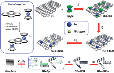
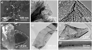
The strategy for the synthesis of iron/nitrogen co-doped porous graphene nanosheets (rGFe-800a) is presented in Fig. 1. Using the typical organometallic ligand-exchange reaction30 between polyaromatic molecules and ferrocene as reported in 1974, cyclopentadienyliron (CpFe) has been successfully attached on carbon nanotubes,23 carbon black and highly oriented pyrolytic graphite31 due to the large amount of six-membered phenyl rings on the surfaces of these materials. Similarly, in our present work, CpFe substituted graphene (rGFeCp) was readily obtained by the reaction of reduced graphene oxide (rG) and ferrocene in anhydrous cyclohexane in the presence of Al/AlCl3. Upon pyrolysis and ammonia activation at 800 °C, the resulting rGFeCp can be easily converted into the nitrogen/iron co-doped porous graphene rGFe-800a. For comparison, iron/nitrogen co-doped porous graphite (GFe-800a) was also prepared under similar reaction conditions using graphite as the starting material instead of rG. Certainly, this concise preparation approach, using low-cost ferrocene and ammonia as iron and nitrogen sources, respectively, makes it possible to produce rGFe-800a on a large scale and further explore its practical applications in a wide range.Obviously, after the ligand-exchange reaction, one of the Cp ligands of each ferrocene molecule was replaced by an unsaturated unit (e.g. benzene ring) in the graphene layer, leading to a covalent bonding of CpFe moiety to the surface of rG through the interaction of the iron atom with the π-electrons of rG.30 Using this mode of attachment, a large number of CpFe units can be efficiently loaded on both the sides of the graphene layers to form sandwich-type rGFeCp composites. The morphologies and microstructures of the as-prepared materials were investigated by scanning electron microscopy (SEM), transmission electron microscopy (TEM), and atomic force microscopy (AFM). As shown in Fig. 2a, free-standing nanosheets with sizes ranging from 250 nm to several micrometers were observed. In addition, rGFeCp also exhibited wrinkles (Fig. 2b) similar to those of rGO. The enlarged TEM image shows typical roughness similar to those observed in previous reports on functionalized graphene oxide.32,33 We further conducted a similar ligand-exchange reaction for the exfoliation of graphite. After stirring the mixture of ferrocene and graphite flakes in organic solvents, e.g. DMF, THF or NMP, for 36 hours, a large amount of free-standing graphene nanosheets (GFeCp) with good dispersibility in these solvents were formed probably due to the attachment of the CpFe moieties on the surface of the graphene sheets (Fig. 2d–f and S2†). After collecting the products by centrifugation, we found that most of the nanosheets consisted of less than ten layers of graphene with a thickness of around 17 nm (Fig. 2g, and S1†). This approach offers a facile way to exfoliate graphite while forming CpFe-modified graphenes. Attempts to achieve high-quality graphene with single or few layers by optimizing the reaction are under way.
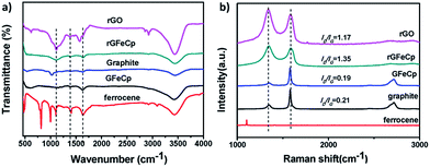
To obtain an insight into the chemical structures of rGFeCp and GFeCp, Fourier transform infrared (FT-IR), Raman and X-ray photoelectron spectroscopies (XPS) were employed (Fig. 3). In the FT-IR spectra (Fig. 3a), the transmittance peaks at 1407 cm−1 and 1635 cm−1 indicated the presence of the aromatic C![[double bond, length as m-dash]](https://www.rsc.org/images/entities/char_e001.gif) C stretch for both rGFeCp and GFeCp. The peak at around 1100 cm−1 confirmed the existence of the iron atoms covalently bonded to the aromatic ring on the graphene/graphite sheets for the both cases.24 Raman spectroscopy has been widely used to characterize the structure of carbon materials, particularly the defects and the degree of ordering of carbon.34 The Raman spectra of graphite, ferrocene, GFeCp, rGFeCp and rG are shown in Fig. 3b. There are two prominent peaks at 1342 and 1587 cm−1, corresponding to the D and G bands, respectively. As is known, the G band is related to the E2g vibration mode of the sp2 carbon domains, which can be used to explain the degree of graphitization, while the D band is associated with structural defects and partially disordered structures of sp2 domains. The intensities of the D bands in rGFeCp and GFeCp are lower than those of rG and graphite, respectively, indicating that partial sp2 domains were restored at different levels after the ligand-exchange reaction.34 Obviously, the CpFe moieties on the surface of the rG or graphene sheets provide buffers between the graphene layers, and thus suppress their deformation and lower the defect density.35
C stretch for both rGFeCp and GFeCp. The peak at around 1100 cm−1 confirmed the existence of the iron atoms covalently bonded to the aromatic ring on the graphene/graphite sheets for the both cases.24 Raman spectroscopy has been widely used to characterize the structure of carbon materials, particularly the defects and the degree of ordering of carbon.34 The Raman spectra of graphite, ferrocene, GFeCp, rGFeCp and rG are shown in Fig. 3b. There are two prominent peaks at 1342 and 1587 cm−1, corresponding to the D and G bands, respectively. As is known, the G band is related to the E2g vibration mode of the sp2 carbon domains, which can be used to explain the degree of graphitization, while the D band is associated with structural defects and partially disordered structures of sp2 domains. The intensities of the D bands in rGFeCp and GFeCp are lower than those of rG and graphite, respectively, indicating that partial sp2 domains were restored at different levels after the ligand-exchange reaction.34 Obviously, the CpFe moieties on the surface of the rG or graphene sheets provide buffers between the graphene layers, and thus suppress their deformation and lower the defect density.35
XPS analyses were also conducted for the characterization of the samples of Cp2Fe, GFeCp and rGFeCp. The Fe2p XPS spectra of ferrocene and rGFeCp are shown in Fig. 4a and b, respectively (also see Fig. S3 in the ESI†). The Fe2p3/2 peak was observed at 707.87 eV, which is similar to that of ferrocene (707.84 eV). The Fe2p spectrum of rGFeCp can be deconvoluted into four peaks at 710.6, 714.2, 722.8, and 724.5 eV. The photoelectron peaks at 724.5 eV correspond to the binding energies of 2p1/2 of Fe(III) and Fe(II) ion,36 and the peaks at 722.8 eV can be assigned to the binding energies of 2p1/2 of Fe(II) ion.37 The peaks at 714.2 eV and 710.6 eV are attributed to the binding energies of 2p3/2 of Fe(II) ion and Fe(III) ion, respectively. In comparison to those peaks of ferrocene, we found that the binding energy was moved to higher levels after the ligand exchange, which indicated the highly efficient functionalization of cyclopentadienyl iron onto the graphene surfaces. These characterizations clearly confirmed that the CpFe moieties have been successfully attached on the surface of rG or graphite in the as-prepared materials through the suggested bonding mode.
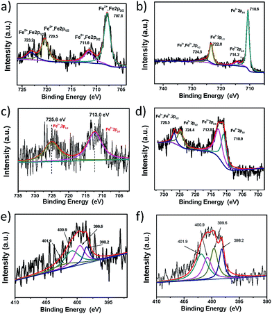 | ||
| Fig. 4 Fe2p XPS spectra of ferrocene (a), rGFeCp (b), rGFe-800 (c), and rGFe-800a (d) and N1s XPS spectra of GFe-800a (e) and rGFe-800a (f). | ||
The pyrolysis of carbon-backbone materials under ammonia can be used to synthesize nitrogen-doped materials with high conductivity and porosity. The as-prepared rGFeCp or GFeCp was first pyrolyzed under a nitrogen flow at 800 °C for 2 h to produce iron-doped graphene (rGFe-800), which was further converted to iron/nitrogen co-doped porous graphene (rGFe-800a) after activation under ammonia gas at 800 °C for 15 min. To examine the elemental composition and iron/nitrogen bonding configurations in GFe-800a and rGFe-800a, XPS analyses of these samples were first carried out. The Fe2p XPS spectra of rGFe-800 and rGFe-800a revealed that the most intense doublet with binding energies of 713.0 eV (Fe 2p1/2) and 725.6 eV (Fe2p3/2) could be attributed to Fe(II) (Fig. 4c and d). After ammonia activation, the new peaks at 710.9 eV (Fe2p1/2) and 724.4 eV (Fe2p3/2) may be attributed to Fe–N bonds.
The bonding configurations of nitrogen in GFe-800a and rGFe-800a were revealed by the N1s core level spectra (Fig. 4e and f). Both the nitrogen spectra can be fitted into four types: pyridinic nitrogen (N1, 398.3 eV), pyrrolic nitrogen (N2, 399.8 eV, or Fe–N), graphitic nitrogen (N3, 401.1 eV), and pyridine-N-oxide (N4, 402.7 eV),34 and all of these play roles in the ORR process.38 The peaks with lower binding energies, located at about 398.3 eV and 399.8 eV, can be attributed to pyridinic nitrogen (N1) and pyrrolic nitrogen (N2, 399.8 eV, or Fe–N), respectively, of which a pair of p-electrons are found in the π-conjugated system of the graphene layers. When carbon atoms within the graphene layers are substituted by nitrogen atoms in the form of “graphitic” nitrogen (N3), the corresponding peak in the high-resolution N1s spectra is located at 400.8–401.3 eV. The high energy peak at 402.3–402.9 eV is commonly attributed to the oxidized nitrogen of pyridine-N-oxide (N4).34 As shown in the N1s spectra, N1 and N2 are the main components in GFe-800a (Fig. 4e). However, N2 and N3 become predominant for rGFe-800a (Fig. 4f). The overall nitrogen contents of GFe-800a and rGFe-800a are 1.07 at% and 2.91 at%, respectively. The results demonstrate that ammonia activation can effectively modulate the chemical states of the nitrogen atoms doped in graphene.
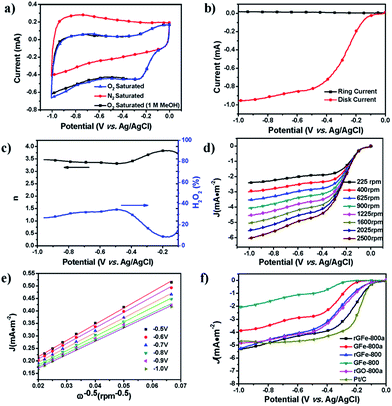
The oxygen reduction reaction (ORR) is of great importance in fuel cells and other electrochemical devices.39 Recently, great efforts have been focused on developing graphene-based materials as effective and low-cost ORR electrocatalysts.38,40 In this respect, the as-prepared materials were examined as electrode materials for ORR catalysis. First, their ORR catalytic activities were evaluated by cyclic voltammetry (CV) (Fig. 5a). The same amount of each sample by mass (0.6 mg cm−2) was loaded onto a glassy-carbon rotating-disk electrode (RDE). As shown in Fig. S4,† with an increase in the pyrolysis temperature from 700 to 900 °C, the onset potentials of rGFe-700, rGFe-800 and rGFe-900 were −0.18 V, −0.14 V and −0.12 V, respectively. rGFe-800 shows the lowest onset potential at −0.12 V, and a relatively high diffusion-limiting current density maximum of 5.3 mA cm−2. Featureless voltammetric currents within the potential range between −1.0 V and 0 V were observed for rGFe-800a and GFe-800a in the nitrogen-saturated solution, but obvious cathodic peaks appeared at −0.25 V and −0.34 V, respectively, when the electrolyte solutions were saturated with O2 (Fig. S5†), which suggests the pronounced electrocatalytic activities of rGFe-800a and GFe-800a for oxygen reduction. To examine possible crossover effects, we measured the electrocatalytic selectivities of rGFe-800a and GFe-800a against the electrooxidation of methanol (a common fuel molecule) in O2-saturated 0.1 M KOH in the presence of methanol (1.0 M). No noticeable changes were observed in the oxygen-reduction currents for these materials (Fig. 5a). Thus, both rGFe-800a and GFe-800a exhibited high selectivity for the ORR with a remarkably good ability to avoid crossover effects, and thus the as-prepared materials hold good promise for their utilization in direct methanol and alkaline fuel cells.
To gain further understanding of the role of rGFe-800a during the ORR electrochemical process, we studied the reaction kinetics by rotating-disk voltammetry. The onset potential for rGFe-800a in RRDE voltammograms was at approximately −0.10 V (Fig. 6b), which is close to that identified from the CV measurements (−0.11 V, Fig. 6a). The calculated electron transfer number and H2O2 concentration were 3.5 and ∼23% at 1.0 V vs. Ag/AgCl (Fig. 6c), respectively, which mainly indicate the direct oxygen to water transformation under the catalysis of rGFe-800a. However, the onset potential for GFe-800a (Fig. S5†) in the RRDE voltammograms was at approximately −0.18 V. The voltammetric profiles in O2-saturated 0.1 M KOH as the electrolyte showed that the current density was enhanced by an increase in the rotation rate (from 400 to 2500 rpm; Fig. 6d). The corresponding Koutecky–Levich plots (Fig. 6e) at various electrode potentials exhibit good linearity. The slopes remain approximately constant over the potential range from −0.5 V to −1.0 V, which suggests that the electron transfer numbers for oxygen reduction at different electrode potentials are similar. The n was calculated to be 3.83 at −0.25 V. In contrast, the calculated n for GFe-800a was only 2.58 at −0.91 V, and the corresponding Koutecky–Levich plots of GFe-800a at various electrode potentials exhibited relatively poor linearity. This result suggests that rGFe-800a leads to a four-electron transfer in oxygen reduction. The calculated kinetic limiting currents for GFe-800a and rGFe-800a reached 13.1 and 15.7 mA cm−2, respectively, which are considerably higher than those of GFe-800 (3.3 mA cm−2) and rGFe-800 (9.2 mA cm−2).
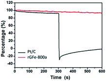 | ||
| Fig. 6 Chronoamperometric responses in O2-saturated 0.1 M KOH after addition (at 300 seconds) of 2% (v/v) methanol for the rGFe-800a (red line) and Pt/C (black line) electrocatalysts at −0.4 V. | ||
The corresponding LSV curves for the carbonized samples and Pt/C in an O2-saturated 0.1 M KOH solution at a rotation rate of 1600 rpm were compared in Fig. 5f. The onset potential for rGFe-800, GFe-800a, GFe-800 and Pt/C are −0.09 V, −0.17 V, −0.25 V and −0.087 V, respectively. rGFe-800a shows the highest current density maximum of 4.86 mA cm−2. However, rGFe-800a has the lowest half-wave potential of −0.29 V and a relatively low onset potential of 0.10 V, which was only 13 mV lower than that of Pt/C (−0.087 V). Therefore, rGFe-800a exhibited better electrocatalytic properties towards the ORR than GFe-800a. The concentration of pyrrolic N and graphitic N in rGFe-800a is 67.3 at%, which is considerably lower in GFe-800a (45.7 at%). This suggests that the pyrrolic N and graphitic N may make great contributions to the ORR catalytic activity.34 Recently, Kim et al. proposed that N-doped edge structures, particularly graphitic N sites, provide the most pronounced improvement for ORR activity41 because the relative electronegativity of the graphitic N atoms reduces the electron density on the adjacent C nuclei, which facilitates the transfer of electrons from the adjacent C to N atoms; moreover, N backdonates electrons.42 Other factors may affect the ORR activities of N-doped carbons, for example the presence or absence of transition metals and the morphologies of the catalysts.43 In addition, the different morphologies of rGFe-800a and GFe-800a might also exert an influence on their catalytic activities (Fig. S6†). The rGFe-800a sample, derived from rGFe, should possess a relatively large specific surface area due to the intercalation of the Fe nanoparticles, which were formed in the process of pyrolysis (Table 1). Therefore, the restacking of graphene in the case of rGFe-800a can be avoided, which allows the active sites residing on the graphene surface to be more easily accessible to O2, and thus makes a large positive contribution to the ORR activities.44–47 On the contrary, the GFe-800a sample, obtained from GfeCp, contain a large amount of stripped graphene sheets with a thickness of around 17 nm. As expected, this type of carbon source would not be beneficial for achieving a high surface area for GFe-800a in the process of pyrolysis; therefore, it is reasonable to believe that the active surface in GFe-800a would be smaller than that of rGFe-800a (Table 1).
| S BET (m2 g−1) | S Langmuir (m2 g−1) | D av (nm) | V tot (cm3 g−1) | |
|---|---|---|---|---|
| a Surface areas calculated from the N2 adsorption isotherm using BET method. b Surface areas calculated from the N2 adsorption isotherm using Langmuir method. c Average pore size based on the adsorption isotherm. d Total pore volume at p/p0 = 0.99. | ||||
| rG | 80.2 | 234.8 | 1.76 | 0.35 |
| rGFeCp | 36.0 | 61.4 | 4.07 | 0.37 |
| rGFe-700 | 60.8 | 115.8 | 2.26 | 0.34 |
| rGFe-800 | 57.5 | 99.1 | 14.2 | 0.41 |
| rGFe-900 | 87.6 | 163.4 | 2.59 | 0.57 |
| rGFe-800a | 57.9 | 105.8 | 9.50 | 0.28 |
We further measured the electrocatalytic selectivity of rGFe-800a and Pt/C against the electro-oxidation of methanol for the ORR, as shown in Fig. 6. After the addition of 2% (v/v) methanol, the ORR current for rGFe-800a was almost unchanged, while Pt/C showed a sharp decrease, and even exhibited a negative current. Therefore, rGFe-800a indeed has a high selectivity for methanol, and enables the effective avoidance of crossover effects; it is superior to the commercially available Pt/C catalyst in this aspect.
Conclusions
In this work, using a ligand-exchange reaction of ferrocene and reduced graphene oxide, CpFe-modified reduced graphene oxide (rGFeCp) was readily obtained. This method can be further used for the exfoliation of graphite into multilayer graphene, and thus for the formation of CpFe-modified multilayer graphene (GFeCp) by a simple one-pot synthesis. The as-produced iron(II) GFeCp exhibits good processability in most of the organic solvents. After pyrolysis and ammonia activation at 800 °C, 2D iron/nitrogen co-doped porous graphene or graphite (rGFe-800a or GFe-800a) were produced. As a non-precious metal catalyst for the oxygen reduction reaction (ORR), rGFe-800a exhibited good electrochemical performance under alkaline conditions (0.1 M KOH) with a low half-wave potential of −0.29 V, a dominant four-electron transfer mechanism (n = 3.5 at −1.0 V) and a maximum diffusion-limiting current density of 4.86 mA cm−2. Moreover, rGFe-800a exhibited high methanol tolerance, superior to that of commercial 20% Pt/C. These characteristics of rGFe-800a demonstrated that the iron/nitrogen co-doping effect enables the efficient improvement of the ORR catalytic activity of graphene-based materials, which might provide a new method of developing composite materials with potentially practical applications in fuel cells and metal–air batteries. In addition, the advantage of the dual role of ferrocene as either an intercalator or functional reactant for the exfoliation of graphite into graphene nanosheets modified with CpFe moieties might represent an efficiently low-cost and green preparation of functional graphene materials on a large-scale.Acknowledgements
This work was financially supported by the National Basic Research Program of China (973 Program: 2013CBA01602, 2012CB933404), the Natural Science Foundation of China (21174083, 51403126 and 21102091), the Shanghai Pujiang Program (12PJ1405300), and Shanghai Jiao Tong University (211 Project), and the Ph.D. Programs Foundation of the Ministry of Education of the People's Republic of China for Young Scholars (20110073120039).Notes and references
- F. Li, J. Song, H. Yang, S. Gan, Q. Zhang, D. Han, A. Ivaska and L. Niu, Nanotechnology, 2009, 20, 455602 CrossRef PubMed.
- S. Stankovich, D. A. Dikin, G. H. Dommett, K. M. Kohlhaas, E. J. Zimney, E. A. Stach, R. D. Piner, S. T. Nguyen and R. S. Ruoff, Nature, 2006, 442, 282 CrossRef CAS PubMed.
- K. S. Novoselov, A. K. Geim, S. V. Morozov, D. Jiang, M. I. Katsnelson, I. V. Grigorieva, S. V. Dubonos and A. A. Firsov, Nature, 2005, 438, 197 CrossRef CAS PubMed.
- T. Hasell, C. D. Wood, R. Clowes, J. T. A. Jones, Y. Z. Khimyak, D. J. Adams and A. I. Cooper, Chem. Mater., 2010, 22, 557 CrossRef CAS.
- Y. Shi, K. K. Kim, A. Reina, M. Hofmann, L. J. Li and J. Kong, ACS Nano, 2010, 4, 2689 CrossRef CAS PubMed.
- X. Wang, L. Zhi and K. Mullen, Nano Lett., 2007, 8, 323 CrossRef PubMed.
- C. Zhang, R. Hao, H. Liao and Y. Hou, Nano Energy, 2013, 2, 88 CrossRef CAS PubMed.
- B. Wang, J. Power Sources, 2005, 152, 1 CrossRef CAS PubMed.
- V. Stamenković, T. J. Schmidt, P. N. Ross and N. M. Marković, J. Electroanal. Chem., 2003, 554–555, 191 CrossRef.
- S. Gottesfeld and T. A. Zawodzinski, Advances in Electrochemical Science and Engineering, Wiley-VCH, 2008, p. 195 Search PubMed.
- E. Antolini, T. Lopes and E. R. Gonzalez, J. Alloys Compd., 2008, 461, 253 CrossRef CAS PubMed.
- C. Cao, X. Zhuang, Y. Su, Y. Zhang, F. Zhang, D. Wu and X. Feng, Polym. Chem., 2014, 5, 2057 RSC.
- J. Yang, D.-J. Liu, N. N. Kariuki and L. X. Chen, Chem. Commun., 2008, 329 RSC.
- S. Yang, L. Zhi, K. Tang, X. Feng, J. Maier and K. Müllen, Adv. Funct. Mater., 2012, 22, 3634 CrossRef CAS.
- D. Wei, Y. Liu, Y. Wang, H. Zhang, L. Huang and G. Yu, Nano Lett., 2009, 9, 1752 CrossRef CAS PubMed.
- C. G. Lee, X. D. Wei, J. W. Kysar and J. Hone, Science, 2008, 321, 385 CrossRef CAS PubMed.
- K. Gong, F. Du, Z. Xia, M. Durstock and L. Dai, Science, 2009, 323, 760 CrossRef CAS PubMed.
- L. S. Panchakarla, A. Govindaraj and C. N. R. Rao, ACS Nano, 2007, 1, 494 CrossRef CAS PubMed.
- J. Zhang, X. Liu, R. Blume, A. Zhang, R. Schlögl and D. S. Su, Science, 2008, 322, 73 CrossRef CAS PubMed.
- F. Cheng and J. Chen, Chem. Soc. Rev., 2012, 41, 2172 RSC.
- Z. Chen, D. Higgins, A. Yu, L. Zhang and J. Zhang, Energy Environ. Sci., 2011, 4, 3167 CAS.
- Q. Liu, H. Zhang, H. Zhong, S. Zhang and S. Chen, Electrochim. Acta, 2012, 81, 313 CrossRef CAS PubMed.
- I. C. Liu, H.-M. Huang, C.-Y. Chang, H.-C. Tsai, C.-H. Hsu and R. C.-C. Tsiang, Macromolecules, 2003, 37, 283 CrossRef.
- L. Fan, Q. Zhang, K. Wang, F. Li and L. Niu, J. Mater. Chem., 2012, 22, 6165 RSC.
- Y. Liang, Y. Li, H. Wang, J. Zhou, J. Wang, T. Regier and H. Dai, Nat. Mater., 2011, 10, 780 CrossRef CAS PubMed.
- L. Zhang, J. Xia, Q. Zhao, L. Liu and Z. Zhang, Small, 2010, 6, 537 CrossRef CAS PubMed.
- X. Wan, G. Long, L. Huang and Y. Chen, Adv. Mater., 2011, 23, 5342 CrossRef CAS PubMed.
- Q. Li, N. Mahmood, J. Zhu, Y. Hou and S. Sun, Nano Today, 2014, 9, 668 CrossRef CAS PubMed.
- H. Yin, C. Zhang, F. Liu and Y. Hou, Adv. Funct. Mater., 2014, 24, 2930 CrossRef CAS.
- W. H. Morrison, E. Y. Hou and D. N. Hendrickson, J. Am. Chem. Soc., 1974, 96, 3603 CrossRef CAS.
- N. Tsubokawa, N. Abe, G. Wei, J. Chen, S. Saitoh and K. Fujiki, Polym. Chem., 2002, 40, 1868 CrossRef CAS.
- D. R. Dreyer, S. Park, C. W. Bielawski and R. S. Ruoff, Chem. Soc. Rev., 2010, 39, 228 RSC.
- X. Huang, X. Qi, F. Boey and H. Zhang, Chem. Soc. Rev., 2012, 41, 666 RSC.
- Z.-H. Sheng, L. Shao, J.-J. Chen, W.-J. Bao, F.-B. Wang and X.-H. Xia, ACS Nano, 2011, 5, 4350 CrossRef CAS PubMed.
- S. Chatrchyan, V. Khachatryan, A. M. Sirunyan, A. Tumasyan, W. Adam, T. Bergauer, M. Dragicevic, J. Erö, C. Fabjan and M. Friedl, Phys. Rev. Lett., 2011, 107, 221804 CrossRef CAS.
- Z. Li, H. Chen, H. Bao and M. Gao, Chem. Mater., 2004, 16, 1391 CrossRef CAS.
- P. Mills and J. L. Sullivan, J. Phys. D: Appl. Phys., 1983, 16, 723 CrossRef CAS.
- L. Qu, Y. Liu, J.-B. Baek and L. Dai, ACS Nano, 2010, 4, 1321 CrossRef CAS PubMed.
- B. C. H. Steele and A. Heinzel, Nature, 2001, 414, 345 CrossRef CAS PubMed.
- R. Liu, D. Wu, X. Feng and K. Müllen, Angew. Chem., Int. Ed., 2010, 122, 2619 CrossRef.
- H. Kim, K. Lee, S. I. Woo and Y. Jung, Phys. Chem. Chem. Phys., 2011, 13, 17505 RSC.
- D. Deng, X. Pan, L. Yu, Y. Cui, Y. Jiang, J. Qi, W.-X. Li, Q. Fu, X. Ma, Q. Xue, G. Sun and X. Bao, Chem. Mater., 2011, 23, 1188 CrossRef CAS.
- G. Wu, K. L. More, C. M. Johnston and P. Zelenay, Science, 2011, 332, 443 CrossRef CAS PubMed.
- Z. S. Wu, L. Chen, J. Liu, K. Parvez, H. Liang, J. Shu, H. Sachdev, R. Graf, X. Feng and K. Müllen, Adv. Mater., 2013, 26, 1450 CrossRef PubMed.
- Z. S. Wu, S. B. Yang, Y. Sun, K. Parvez, X. L. Feng and K. Müllen, J. Am. Chem. Soc., 2012, 134, 9082 CrossRef CAS PubMed.
- Z. S. Wu, W. Ren, L. Gao, B. Liu, C. Jiang and H. M. Cheng, Carbon, 2009, 47, 493 CrossRef CAS PubMed.
- Z. S. Wu, W. Ren, L. Gao, J. Zhao, Z. Chen, B. Liu, D. Tang, B. Yu, C. Jiang and H. M. Cheng, ACS Nano, 2009, 3, 411 CrossRef CAS PubMed.
Footnotes |
| † Electronic supplementary information (ESI) available: Preparation details, TGA spectra, AFM images, XPS surveys, XRD spectra, ORR performance of GFe-800a, and elemental analysis based on XPS analysis. See DOI: 10.1039/c5ta00556f |
| ‡ These two authors contributed equally to this work. |
| This journal is © The Royal Society of Chemistry 2015 |

