Vertically oriented MoS2 and WS2 nanosheets directly grown on carbon cloth as efficient and stable 3-dimensional hydrogen-evolving cathodes†
Ya
Yan
a,
BaoYu
Xia
 a,
Nan
Li
a,
Zhichuan
Xu
b,
Adrian
Fisher
c and
Xin
Wang
*a
a,
Nan
Li
a,
Zhichuan
Xu
b,
Adrian
Fisher
c and
Xin
Wang
*a
aSchool of Chemical and Biomedical Engineering, Nanyang Technological University, 50 Nanyang Avenue, 639798, Singapore. E-mail: WangXin@ntu.edu.sg; Fax: +65 67947553
bSchool of Materials Science and Engineering, Nanyang Technological University, Singapore 639798, Singapore
cDepartment of Chemical Engineering and Biotechnology, University of Cambridge, New Museums Site, Pembroke Street, Cambridge, CB2 3RA, UK
First published on 7th November 2014
Abstract
The development of non-noble-metal based hydrogen-evolving catalysts is essential to the practical application of water-splitting devices. Improvement of both the activity and stability of such catalysts remains a key challenge. In this work, a simple solvothermal method is developed to directly grow MoS2 and WS2 on carbon cloth with vertically oriented nanosheet layers. With the unique layer orientation that maximally exposes active edge sites as well as a rapid release of small gas bubbles to maintain a large working area, such prepared 3-dimensional electrodes exhibit high activity towards the HER. In addition, they also exhibit prominent electrochemical durability, thanks to the strong bonding between the nanosheet layers and the substrate along with the self-removal of the as-formed H2 bubbles from the nano-porous electrode surface.
Hydrogen generation through water electrolysis has been extensively investigated as an attractive way to store energy from renewable sources.1,2 The most effective electrocatalytic materials for the hydrogen evolution reaction (HER) are Pt group metals, but their high cost and scarcity limits their widespread use.3 As such, developing efficient and inexpensive HER catalysts with high stability is highly desirable but remains challenging. So far, both theoretical and experimental studies have highlighted the great promise of layered transitional-metal dichalcogenides (LTMDs), such as molybdenum disulfide (MoS2) and its derivatives, as efficient and low cost catalysts for hydrogen evolution.4–7 Tungsten disulfide (WS2) has an analogous structure to MoS2 and these compounds share similar physical and chemical properties. Thus WS2 has also received some attention as an electrocatalyst for the HER for almost 20 years.8–11
Since the edges of MoS2 were identified as active sites for the HER,12 a lot of research efforts have been focused on the growth of MoS2/WS2 nanostructures that maximally expose active edge sites for large-scale applications.13–16 Previously, Cui et al. first demonstrated a thin film structured HER electrode with vertically aligned MoS2 molecular layers grown on flat substrates.17 Later, the same approach was extended to the growth of MoSe2 on rough and curved surfaces in an attempt to increase the exposed edges,18 as the number of the exposed edge sites is still limited on the flat substrates. Unfortunately, the fabrication process of the nanostructured HER electrodes is rather complicated and also difficult to control. Recently, Jiang et al. successfully demonstrated the construction of the vertically aligned MoS2 nanoplatelet electrode with a “superaerophobic” surface, which allows efficient removal of gas bubbles and ensures high electrochemical activity.13 Unfortunately, the use of expensive flat Ti foil as a substrate seems to limit the maximal exposure of active sites as well as its scalable application due to the high cost. Carbon cloth (CC), an easily available and cheap carbon fiber, is highly conductive and flexible. Its use as an electrode support bears the intrinsic benefits of low cost, robustness and a self-standing 3D structure. Although 3D electrodes composed of WS2 or MoS2 nanoparticles on carbon cloth have been reported, there is no report on the direct growth of vertically aligned MoS2 nanoplatelets on carbon cloth which is of great significance for the practical application of water-splitting devices.
Herein, we demonstrate a simple way to fabricate vertically oriented MoS2 and WS2 nanosheet thin films grown on CC as efficient 3D electrodes for the HER (details are available in the ESI†). Thanks to the nanostructured films composed of vertically aligned layers, resulting in a large number of exposed active edges and timely repelling of as-formed H2 bubbles, the well-designed 3D electrodes showed much higher electrochemical activities than flat MoS2 and WS2 nanosheets on CC.
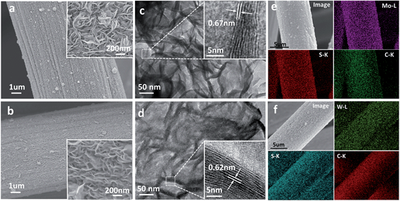
Fig. 1a & b show the low-magnification scanning electron microscopy (SEM) images of MoS2/CC (a) and WS2/CC (b), indicating that the entire surface of the CC was uniformly covered with a layer of the MoS2/WS2 nanosheet film. These films possessed a porous structure with only ∼100 nm depth (Fig. S1,† as indicated by the black arrows). The high-magnification SEM images (insets of Fig. 1a & b) further reveal that such MoS2/WS2 nanosheets are vertically aligned on the CC surface, possessing a lateral size of around 200–300 nm. The corresponding energy dispersive X-ray (EDX) spectra (see Fig. S2†) suggest that the atomic ratio between Mo/W and S is close to 2![[thin space (1/6-em)]](https://www.rsc.org/images/entities/char_2009.gif) :
:![[thin space (1/6-em)]](https://www.rsc.org/images/entities/char_2009.gif) 1. CC is a porous 3D electrode consisting of a carbon fiber of 8 μm diameter (see Fig. S3†). The highly textured surface of the carbon fiber facilitates the nucleation and growth of a sulfide layer with strong mechanical interaction. It is noted that, after annealing at 350 °C for 2 h, the 2D nanosheet morphology is intact and the 3D porous architectures are well retained (Fig. S4a & b†). Fig. 1c & d are representative transmission electron microscopy (TEM) images of the MoS2 and WS2 nanosheet films, respectively, showing good agreement with SEM observation (Fig. 1a & b). The light contrast in various areas of the TEM image indicates the thin two-dimensional (2D) nature. Moreover, the high-resolution (HR) TEM image (inset of Fig. 1c) of the curled edge shows that those MoS2 nanosheets are composed of 7–10 layers (4–6 nm) with an interlayer spacing of 0.67 nm, while the WS2 nanosheets show a thickness of ∼10 nm with an interlayer distance of 0.62 nm (inset of Fig. 1d), verifying the ultrathin nature of these vertically oriented MoS2/WS2 nanosheets. Fig. 1e & f show the SEM images and the corresponding EDX elemental mapping images of the as-prepared MoS2/CC and WS2/CC electrodes, respectively, revealing that both Mo/W and S elements are uniformly distributed on the whole nanofiber.
1. CC is a porous 3D electrode consisting of a carbon fiber of 8 μm diameter (see Fig. S3†). The highly textured surface of the carbon fiber facilitates the nucleation and growth of a sulfide layer with strong mechanical interaction. It is noted that, after annealing at 350 °C for 2 h, the 2D nanosheet morphology is intact and the 3D porous architectures are well retained (Fig. S4a & b†). Fig. 1c & d are representative transmission electron microscopy (TEM) images of the MoS2 and WS2 nanosheet films, respectively, showing good agreement with SEM observation (Fig. 1a & b). The light contrast in various areas of the TEM image indicates the thin two-dimensional (2D) nature. Moreover, the high-resolution (HR) TEM image (inset of Fig. 1c) of the curled edge shows that those MoS2 nanosheets are composed of 7–10 layers (4–6 nm) with an interlayer spacing of 0.67 nm, while the WS2 nanosheets show a thickness of ∼10 nm with an interlayer distance of 0.62 nm (inset of Fig. 1d), verifying the ultrathin nature of these vertically oriented MoS2/WS2 nanosheets. Fig. 1e & f show the SEM images and the corresponding EDX elemental mapping images of the as-prepared MoS2/CC and WS2/CC electrodes, respectively, revealing that both Mo/W and S elements are uniformly distributed on the whole nanofiber.
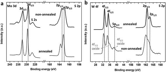
To further characterize the chemical nature and bonding state of MoS2/WS2 on CC surfaces, X-ray photoelectron spectroscopy (XPS) was employed. As shown in Fig. 2a, two characteristic peaks arising from Mo 3d5/2 and Mo 3d3/2 orbitals are located at 229.1 eV and 232.2 eV, suggesting the dominance of Mo(IV) in the freshly prepared MoS2/CC product. Besides, small shoulder signals for the Mo(VI) oxidation state are observed. In contrast, the Mo 3d spectrum of the annealed sample shows only a single doublet. Furthermore, the S 2p3/2–1/2 doublet peaks of the freshly prepared MoS2 exhibit broader peaks at ∼163 eV and 162 eV when compared with those of the annealed sample, indicating the existence of other binding signals, such as bridging S22− or apical S2−, which could result from the unsaturated S atoms and are known as active sites for the HER.19,20 Thus better HER performance can be expected from the freshly prepared S-rich MoS2 sample.
 | ||
| Fig. 2 XPS spectra of Mo 3d and S 2p in the MoS2/CC sample (a) and W 4f and S 2p in the WS2/CC sample (b), as-synthesized and after thermally annealed at 350 °C. | ||
Fig. 2b shows the high-resolution XPS spectra of the W 4f and S 2p regions of the WS2/CC products. For the WS2/CC composite after annealing, black dotted lines have been added to bisect the W 4f7/2, W 4f5/2 and W 5p3/2 peaks which appeared at about 33.1 eV, 35.2 eV and 38.7 eV, suggesting an oxidation state of W(IV), and the corresponding single doublet peaks of S 2p1/2 and 2p3/2 appeared at 162.4 eV and 163.6 eV, indicating S2−. These peaks in the annealed WS2/CC are identical to those of highly crystalline WS2.21 For the freshly obtained WS2/CC, the doublet peaks of W 4f and S 2p were broader than those of the annealed WS2/CC. Besides, a small negative shift of about 0.5 eV was observed, which could be attributed to the adsorption of oxygen,22 while the small shoulder observed at ∼36 eV illustrates the existence of W(VI) in an oxygen-rich environment as in WO3.23,24 This indicates that the freshly prepared WS2/CC is more susceptible to oxidation.25 It has been reported that the WS2 sample appears to be more susceptible to oxidation than MoS2.8
For MoS2 materials, the basal edges have been identified as the active sites for the HER, but unfortunately, the overall conductivity of such materials is limited due to the poor electron transport among the domains and it thus reduces the total HER activity. In this work, the vertically oriented MoS2/WS2 nanosheet film grown on CC (a rough and curved surface) is expected to not only maximize the exposed active sites and overcome the limited electron/proton transport, but also accelerate the timely repelling of the as-formed bubbles by reducing the gas bubble adhesion due to the highly ‘superaerophobic’ surface.12
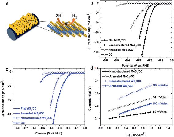
To verify our hypothesis, the HER performance of the 3D MoS2/CC and WS2/CC electrodes was demonstrated in 0.5 M H2SO4 solution using a three-electrode setup, where the electrode was tested in a static state without rotation to mimic real industrial operation. Electrochemical impedance spectroscopy (EIS) reveals a similar system resistance (Rs, 2.5 ± 0.3 Ω) for all the tested electrodes (Fig. S5†). To exclude the influence of the series resistance from the system (Rs, such as wiring, solution and substrate), all the data have been iR-corrected by subtracting the ohmic resistance loss from the overpotential. As control samples, flat MoS2/CC and WS2/CC films were also prepared and characterized by SEM (Fig. S6†) and XPS (Fig. S7†). As shown in Fig. 3b, the cathodic polarization curve recorded for the nanostructured MoS2/CC exhibited a low onset potential of ∼0.1 V, which is much smaller than that of the flat MoS2/CC and annealed MoS2/CC and even lower than that of the reported Ti foil supported MoS2 nanostructure.13 As expected, our nanostructured MoS2/CC electrode displays the highest current density among all the tested electrodes, 86 mA cm−2 at an overpotential of around −0.25 V. This is equivalent to ∼450 mA mg−1 after being normalized by the loading weight, which is almost two times larger than the value of the Ti foil supported MoS2 nanostructure.13 Since the cathodic current density is proportional to the amount of evolved hydrogen, the large current density here indicates the prominent hydrogen evolution behavior of the vertically grown MoS2/CC electrode. This may arise from the uniquely designed electrode structure which brings in more active sites along with the optimized conductivity and reduced gas bubble adhesion.
Interestingly, in the case of the WS2/CC electrodes (Fig. 3c), the annealed nanostructured WS2/CC showed the highest current density (∼15 mA cm−2) among the tested WS2 samples at an overpotential of −0.25 V. Although the annealed WS2/CC electrode shows lower activity than the nanostructured MoS2/CC with a 0.15 V larger overpotential to achieve a cathodic current density of 86 mA cm−2, it is still noteworthy because after being normalized by the loading weight, this value (∼15 mA cm−2 at −0.25 V) is about 7 times larger than that of carbon cloth supported WS2 nanoparticles23 and even slightly higher than that of WS2/rGO.26 This is likely due to the vertically oriented feature of our WS2/CC electrode. It is noted that the annealed WS2/CC electrode displays much higher activity than the as-prepared WS2/CC, this may be attributed to the removal of inactive impurities such as WO3,23 as verified by the XPS analysis.
The Tafel plots of these catalysts are shown in Fig. 3d and are used to determine Tafel slopes and exchange current densities by fitting the Tafel plots to the equation η = b![[thin space (1/6-em)]](https://www.rsc.org/images/entities/char_2009.gif) log(j) + log(j0), where η is the overpotential, j is the current density, j0 is the exchange current density, and b is the Tafel slope.27 The fitted Tafel plot of the nanostructured MoS2/CC gives a b value of 50 mV dec−1, which is much lower than that of the annealed MoS2/CC and even slightly smaller than the recently reported value for pure MoS2 nanoplates (53 mV dec−1).28 It is likely due to the oriented growth of MoS2 nanosheets on CC which results in the improvement of the conductivity of the MoS2 materials and the increase in the number of the exposed active sites. Then the exchange current density is determined to be 9.2 × 10⁻³ mA cm−2 for the nanostructured MoS2/CC sample, almost one order of magnitude higher than the Ti foil supported MoS2 nanostructure (3.87 × 10⁻⁴ mA cm−2)13 and carbon fiber paper supported MoSe2 (3.80 × 10⁻⁴ mA cm−2).18 Although the Tafel slope for annealed WS2/CC is smaller than the freshly prepared nanostructured WS2/CC, this is still much higher than that of the MoS2 and consistent with previous results.23,26 Moreover, these values compare favorably with most of the reported values for non-precious HER catalysts in acidic aqueous electrolytes (see Table S1 in the ESI†).
log(j) + log(j0), where η is the overpotential, j is the current density, j0 is the exchange current density, and b is the Tafel slope.27 The fitted Tafel plot of the nanostructured MoS2/CC gives a b value of 50 mV dec−1, which is much lower than that of the annealed MoS2/CC and even slightly smaller than the recently reported value for pure MoS2 nanoplates (53 mV dec−1).28 It is likely due to the oriented growth of MoS2 nanosheets on CC which results in the improvement of the conductivity of the MoS2 materials and the increase in the number of the exposed active sites. Then the exchange current density is determined to be 9.2 × 10⁻³ mA cm−2 for the nanostructured MoS2/CC sample, almost one order of magnitude higher than the Ti foil supported MoS2 nanostructure (3.87 × 10⁻⁴ mA cm−2)13 and carbon fiber paper supported MoSe2 (3.80 × 10⁻⁴ mA cm−2).18 Although the Tafel slope for annealed WS2/CC is smaller than the freshly prepared nanostructured WS2/CC, this is still much higher than that of the MoS2 and consistent with previous results.23,26 Moreover, these values compare favorably with most of the reported values for non-precious HER catalysts in acidic aqueous electrolytes (see Table S1 in the ESI†).
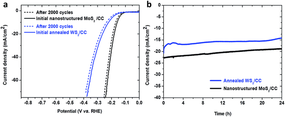
Stability is another important criterion used to evaluate a catalyst. A long-term cyclic voltammetry test was performed to assess the electrochemical stability of the nanostructured MoS2/CC electrode in an acidic environment. As shown in Fig. 4a, working under such conditions, the nanostructured MoS2/CC electrode and the annealed WS2/CC electrode performed still steadily, suggested by the smooth curve recorded after 2000 cycles along with negligible current degradation. Furthermore, a continuous chronoamperometric curve is also presented in Fig. 4b, where a stable current density of ∼22 mA cm−2 (at an overpotential of 0.2 V) and ∼17 mA cm−2 (at an overpotential of 0.25 V) over an operating period of 24 h was observed for the nanostructured MoS2/CC and annealed WS2/CC, respectively, further revealing the high stability of these nanostructured electrodes. Although, for a practical electrode device, the stability performance will need to be maintained for a much longer time, the performance of the as-prepared electrodes in this work shows great potential for scalable applications. Notably, our MoS2/CC and WS2/CC electrodes are robust enough to withstand an ultrasonication treatment even for 30 min (Fig. S8†), indicating the strong binding between the CC and the nanostructured MoS2/WS2 sheets, which ensures the excellent stability of those nanostructured electrodes. Notably, it is observed that the small H2 bubbles formed on the 3D electrode can be timely released during the working process, which in turn ensures a sufficient number of active sites, resulting in a stable electrocatalytic performance (details can be seen in SI-2†). This is fully consistent with the previous observation.13
As discussed above, such high catalytic performance of the nanostructured MoS2/WS2 electrodes could be due to the following reasons: (1) the intimate contact of MoS2 and WS2 nanosheets with CC enables good mechanical binding and electrical connection, facilitating the flow of electrons from CC to MoS2 or WS2 nanosheet arrays during the HER. This is of great significance for the semi-conductive catalysts such as MoS2 and WS2. (2) The 3D configurations of the vertically oriented MoS2/CC and WS2/CC electrodes not only facilitate the self-removal of as-formed H2 bubbles from the nano-porous electrode surfaces, but also ensure sufficient and open spaces which allow the easy diffusion of the electrolyte into all the active sites and thus a more efficient use of the entire electrode. (3) The ultrathin MoS2/WS2 vertical nanosheets could be a better structure compared to the multilayer nanoparticles because electrons only need to be transferred from the support to the platelets, instead of passing through different layers. (4) The vertically oriented S-rich MoS2 nanosheet arrays and the annealed WS2 nanosheets with low oxidized species expose more active sites for the HER than those of flat ones.
In summary, we developed a simple solvothermal method to fabricate MoS2 and WS2 grown on CC electrodes with vertically oriented nanosheet layers. With the unique layer orientation that maximally exposes the active edge sites as well as a rapid release of small gas bubbles to provide a constant working electrode area, the nanostructured MoS2/CC electrode exhibits excellent HER activity, while the WS2/CC catalyst is also investigated here as a novel active HER architecture for potential use as a HER catalyst. Both materials exhibit prominent electrochemical durability, thanks to the strong bonding between the nanosheet layers and the substrate along with the self-removal of the as-formed H2 bubbles from the nano-porous electrode surface. Moreover, these vertically oriented layered catalysts can be readily applied in diverse water electrolysis devices as easily available, high-performance and stable HER catalysts.
Acknowledgements
This project is funded by the National Research Foundation (NRF), Prime Minister's Office, Singapore under its Campus for Research Excellence and Technological Enterprise (CREATE) programme. We also acknowledge financial support from the academic research fund AcRF tier 1 (M4011020 RG8/12 and M4011253 RG 7/14) Ministry of Education, Singapore.References
- J. A. Turner, Science, 2004, 305, 972–974 CrossRef CAS PubMed.
- J. N. Armor, Catal. Lett., 2005, 101, 131–135 CrossRef CAS PubMed.
- M. G. Walter, E. L. Warren, J. R. McKone, S. W. Boettcher, Q. Mi, E. A. Santori and N. S. Lewis, Chem. Rev., 2010, 110, 6446–6473 CrossRef CAS PubMed.
- M.-R. Gao, Y.-F. Xu, J. Jiang and S.-H. Yu, Chem. Soc. Rev., 2013, 42, 2986–3017 RSC.
- A. B. Laursen, S. Kegnaes, S. Dahl and I. Chorkendorff, Energy Environ. Sci., 2012, 5, 5577–5591 CAS.
- M. Chhowalla, H. S. Shin, G. Eda, L.-J. Li, K. P. Loh and H. Zhang, Nat. Chem., 2013, 5, 263–275 CrossRef PubMed.
- Y. Yan, B. Xia, X. Qi, H. Wang, R. Xu, J.-Y. Wang, H. Zhang and X. Wang, Chem. Commun., 2013, 49, 4884–4886 RSC.
- M. A. Lukowski, A. S. Daniel, C. R. English, F. Meng, A. Forticaux, R. J. Hamers and S. Jin, Energy Environ. Sci., 2014, 7, 2608–2613 CAS.
- D. Voiry, H. Yamaguchi, J. Li, R. Silva, D. C. B. Alves, T. Fujita, M. Chen, T. Asefa, V. B. Shenoy, G. Eda and M. Chhowalla, Nat. Mater., 2013, 12, 850–855 CrossRef CAS PubMed.
- J. Lin, Z. Peng, G. Wang, D. Zakhidov, E. Larios, M. J. Yacaman and J. M. Tour, Adv. Energy Mater., 2014, 4 DOI:10.1002/aenm.201301875.
- Z. Wu, B. Fang, A. Bonakdarpour, A. Sun, D. P. Wilkinson and D. Wang, Appl. Catal., B, 2012, 125, 59–66 CrossRef CAS PubMed.
- T. F. Jaramillo, K. P. Jørgensen, J. Bonde, J. H. Nielsen, S. Horch and I. Chorkendorff, Science, 2007, 317, 100–102 CrossRef CAS PubMed.
- Z. Lu, W. Zhu, X. Yu, H. Zhang, Y. Li, X. Sun, X. Wang, H. Wang, J. Wang, J. Luo, X. Lei and L. Jiang, Adv. Mater., 2014, 26, 2683–2687 CrossRef CAS PubMed.
- Y. Yan, B. Xia, Z. Xu and X. Wang, ACS Catal., 2014, 1693–1705 CrossRef CAS.
- Y. H. Chang, F. Y. Wu, T. Y. Chen, C. L. Hsu, C. H. Chen, F. Wiryo, K. H. Wei, C. Y. Chiang and L. J. Li, Small, 2013, 10, 895–900 CrossRef PubMed.
- P. D. Tran, S. S. Pramana, V. S. Kale, M. Nguyen, S. Y. Chiam, S. K. Batabyal, L. H. Wong, J. Barber and J. Loo, Chem.–Eur. J., 2012, 18, 13994–13999 CrossRef CAS PubMed.
- D. Kong, H. Wang, J. J. Cha, M. Pasta, K. J. Koski, J. Yao and Y. Cui, Nano Lett., 2013, 13, 1341–1347 CrossRef CAS PubMed.
- H. Wang, D. Kong, P. Johanes, J. J. Cha, G. Zheng, K. Yan, N. Liu and Y. Cui, Nano Lett., 2013, 13, 3426–3433 CrossRef CAS PubMed.
- D. Merki, S. Fierro, H. Vrubel and X. L. Hu, Chem. Sci., 2011, 2, 1262–1267 RSC.
- D. Li, U. Maiti, J. Lim, D. S. Choi, W. J. Lee, Y. Oh, G. Y. Lee and S. O. Kim, Nano Lett., 2014, 14, 1228–1233 CrossRef CAS PubMed.
- R. Morrish, T. Haak and C. A. Wolden, Chem. Mater., 2014, 26, 3986–3992 CrossRef CAS.
- I. Martin, P. Vinatier, A. Levasseur, J. C. Dupin and D. Gonbeau, J. Power Sources, 1999, 81–82, 306–311 CrossRef CAS.
- T.-Y. Chen, Y.-H. Chang, C.-L. Hsu, K.-H. Wei, C.-Y. Chiang and L.-J. Li, Int. J. Hydrogen Energy, 2013, 38, 12302–12309 CrossRef CAS PubMed.
- A. Benadda, A. Katrib, J. W. Sobczak and A. Barama, Appl. Catal., A, 2004, 260, 175–183 CrossRef CAS PubMed.
- B. K. Miremadi and S. R. Morrison, J. Appl. Phys., 1988, 63, 4970–4974 CrossRef CAS PubMed.
- J. Yang, D. Voiry, S. J. Ahn, D. Kang, A. Y. Kim, M. Chhowalla and H. S. Shin, Angew. Chem., Int. Ed., 2013, 52, 13751–13754 CrossRef CAS PubMed.
- J. O. M. Bockris and E. C. Potter, J. Electrochem. Soc., 1952, 99, 169–186 CrossRef CAS PubMed.
- Y. Yan, B. Xia, X. Ge, Z. Liu, J.-Y. Wang and X. Wang, ACS Appl. Mater. Interfaces, 2013, 5, 12794–12798 CAS.
Footnote |
| † Electronic supplementary information (ESI) available: Experimental section and figures, and a video. See DOI: 10.1039/c4ta04858j |
| This journal is © The Royal Society of Chemistry 2015 |


