 Open Access Article
Creative Commons Attribution 3.0 Unported Licence
Design of a Kagome lattice from soft anisotropic particles†
Szilard N.
Fejer
*ab and
David J.
Wales
c
aDepartment of Chemical Informatics, Faculty of Education, University of Szeged, Boldogasszony sgt. 6, H-6725, Szeged, Hungary. E-mail: szilard.fejer@cantab.net
bPro-Vitam Ltd., str. Muncitorilor nr. 16, Sfantu Gheorghe, Romania
cDepartment of Chemistry, University of Cambridge, Lensfield Road, Cambridge, CB2 1EW, UK
First published on 20th July 2015
Abstract
We present a simple model of triblock Janus particles based on discoidal building blocks, which can form energetically stabilized Kagome structures. We find ‘magic number’ global minima in small clusters whenever particle numbers are compatible with a perfect Kagome structure, without constraining the accessible three-dimensional configuration space. The preference for planar structures with two bonds per patch among all other possible minima on the landscape is enhanced when sedimentation forces are included. For the building blocks in question, structures containing three bonds per patch become progressively higher in energy compared to Kagome structures as sedimentation forces increase. Rearrangements between competing structures, as well as ring formation mechanisms are characterised and found to be highly cooperative.
1 Introduction
Designing nanoscale building blocks that self-assemble into complex structures is an active area of contemporary research.1–4 In particular, a promising approach for fabricating novel materials is to design colloidal building blocks of various shapes, sizes and anisotropy,5,6 which can assemble into the desired structure under certain experimental conditions. Interactions between particles can be fine-tuned on the colloidal length scale by changing external conditions, such as the ionic strength of the solution. The shape and interaction anisotropy of the particles is a key property defining the shape of the overall assembly.7 New experimental techniques allow for the realisation of building blocks with exotic shapes.8 Using computational techniques therefore has a high predictive value, allowing for rational design of novel building blocks, and for studying their parameter space and self-assembly propensity.Inspired by experimental results from the Granick group9 for triblock Janus particles that assemble into an open Kagome structure during sedimentation, we present a design for particles interacting via a soft anisotropic potential, which exhibit Kagome structures as the energetic ground state for small clusters. Our design is different from the model of Romano et al.,10 which is based on the Kern–Frenkel model,11 where the particles are constrained in two dimensions, and the potential includes hard sphere interactions. Our model has no geometrical constraints, enabling us to investigate the assembly process in three dimensions, along with the effect of gravity. The interparticle interactions are also continuous, making it possible to study the energy landscapes in detail, including rearrangement mechanisms and pathways between competing morphologies.
Entropy has been shown to stabilize open colloidal lattices for triblock Janus particles.12 In particular, two effects are known to be important: the freedom of the particles to rotate, as long as two hydrophobic patches are in contact, and vibrational entropy terms that disfavour hexagonal close packed structures, due to the proximity of the central bands interacting via screened Coulombic repulsion. Such colloidal building blocks do not possess strongly directional interactions during dimerisation: a dimer has the same energy irrespective of the relative orientation of the monomers for configurations in which the hydrophobic patches are in contact.
Although the current experimental realisations of triblock Janus particles have hydrophobic patches that interact uniformly with neighbouring patches, it is possible to make short-range interactions more directional.13 In the present contribution we explore the assembly properties of a triblock Janus-like anisotropic particle, in which the directionality of the interparticle potential is a crucial factor in stabilizing open lattice structures.
2 Building block design
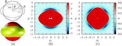
In the experimental setup,9 colloidal triblock Janus particles preferentially form a Kagome lattice if each particle has four nearest neighbours, each hydrophobic patch interacting with two particles. To achieve this result, the hydrophobic patch has to be wide enough at both poles of the particle. The triblock Janus particles are polystyrene spheres with a hydrophobic coating around two opposite poles. Hence a repulsive band is formed in the middle, and the range of the repulsion can be tuned by changing the ionic strength of the solution.In our design, we keep the D∞h symmetry of the particle, and use two, rigidly linked concentric ellipsoids with different properties (Fig. 1). Our aim is to represent the ‘shape’ of the triblock Janus building block using only ellipsoids. Ellipsoid B is in fact a ‘sticky’ sphere, associated with isotropic attractions. The middle band is replaced by an oblate ellipsoid (A) with an aspect ratio of 0.6, and the two equal axes are chosen somewhat larger than the diameter of ellipsoid B, so that only a part of this ellipsoidal surface protrudes outside the sphere defined by ellipsoid B. Ellipsoid A is purely repulsive in character. Each ellipsoid in one building block interacts with all ellipsoids in the other building blocks via the Paramonov–Yaliraki (PY) potential.14 We have used the PY potential before to design anisotropic building blocks that self-assemble into complex structures to represent helices,7 amyloid fibres, virus capsids, tubes,15 and more recently, Bernal spirals.16 The potential is implemented in the angle-axis rigid body framework.17,18 The interaction energy between two building blocks has the following form:
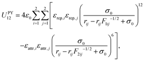 | (1) |
The appearance of each building block resembles a ‘flying saucer’, and the most important characteristic is the shape of the interparticle potential experienced by another particle. Since we are interested in the assembly of clusters, and the particles are anisotropic, the best way to illustrate the forces around a building block is to examine the potential energy surface for two particles. Fig. 1b and c illustrate two limits, and the possible isosurfaces that can be drawn, depending on the relative orientation of two particles. The interparticle potential and its first derivative are continuous for non-overlapping configurations. Discontinuities may arise for large overlaps, but steps resulting in overlapping configurations are prohibited in our calculations.
The strongest interaction between two particles arises when they point along their poles, despite the attraction of ellipsoid B being uniform in every direction. This result is due to the strength of the repulsive term given by ellipsoid A, since the distance between that oblate ellipsoid and the surface of ellipsoid B is greatest at the poles, and we do not cut off the interaction range for the repulsive ellipsoid. The attractive well is nevertheless wide around the poles, so rotational moves are still possible in bonded configurations, but they are not isoenergetic, and correspond to floppy modes.
In the corresponding experimental setup9 no tetrahedral configurations have been observed, and the two bond per patch limit is one of the driving forces of assembly. In contrast, we focus on building block properties that facilitate the selection of Kagome structures instead of more complex configurations, where three bonds per patch are possible. When choosing the parameters described above, we did not bias our selection to restrict stable configurations to two nearest neighbours per patch. In our model the tetrahedral arrangement (three neighbours per patch) competes with the planar configuration (two neighbours per patch). For example, the global minimum for seven particles is a planar structure exhibiting nine patches with two neighbours, and it is only 0.13 energy units lower than a fused tetrahedral arrangement with eight patches that have three nearest neighbours each. The global minimum for a four-particle cluster is a tetrahedron, rather than a Y-shaped planar structure, which lies 0.26ε0 higher in energy.
To study the effect of gravity on the energy landscape, we add an extra distance-dependent term in the z direction, representing a constant force pulling each particle towards a soft repulsive wall in the xy plane (Ug). The total energy of a system with N particles is then
 | (2) |
| Ug = dz−12 + εgdz. | (3) |
To examine the effect of gravity we have mapped the energy landscapes for small clusters using three different values for εg: 0 (no gravity effects), 0.0165 and 0.165 (in units of ε0/l0). Comparing the results enables us to investigate the effect of the particle density on assembly kinetics.
3 Methods
To locate the global minima for clusters composed of the building blocks described above, we employed basin-hopping global optimization,20–22 implemented in the GMIN program.23 The dynamics were studied by constructing kinetic transition networks by discrete path sampling,24–26 using the OPTIM and PATHSAMPLE programs.23 Transition state candidates were located with the doubly-nudged elastic band method,27 adapted to avoid overlapping configurations of the particles during interpolation.16 The candidates were then refined using a gradient-only hybrid eigenvector-following method.28 To visualize the energy landscapes, reduced representations were created by constructing disconnectivity graphs.29,30 This methodology has been employed in many previous studies and extensively reviewed.26,31,32 Integrated path lengths shown for the various rearrangements include particle rotations. The path lengths were calculated using the displacement of the centre of each ellipsoid in the rigid body, which coincide in the Kagome building blocks, and two reference sites located symmetrically at a distance of 1l0 from the centre of mass, along the z axis (the symmetry axis of the building block). An algorithm based on interparticle distances and connectivity was used to detect minima containing patches with three nearest neighbours (tetrahedral bonding configuration).4 Results
4.1 Global optimization
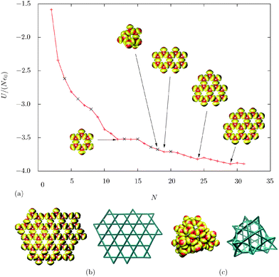
We have predicted the global minima for cluster sizes N = 2 to 31, as well as for two larger clusters (N = 72 and 100). For the larger clusters, it was necessary to use continuous cutoffs for the interaction potential, to speed up the calculation. At N = 12, we find a ‘magic number’ in the energy/particle diagram. In this system, the global minimum consists of two staggered triangles, characteristic of the Kagome lattice.Edge effects are very important in small clusters. These building blocks try to maximise the overall number of close contacts between patches, and minimise the number of particles with less than ideal contacts. The competition between these two trends results in global minima containing tetrahedral particles, for certain cluster sizes (Fig. 2). However, none of the structures containing three-bonded patches are ‘magic numbers’. The other ‘magic number’ global minima are perfect Kagome structures with more rings (N = 19, 24 and 29), containing only particles with two bonds per each patch (and those at the edge of the lattice).
The Kagome lattice is quite floppy, which provides another way to minimise edge effects. Once the lattice grows to a size that enables it to close up, the global minimum becomes a hollow structure when no gravity effects are considered. This situation occurs for N = 100, while at N = 72 the global minimum is still a Kagome lattice (Fig. 2b and c). In the hollow structure, almost all particles with an unbound patch are in a tetrahedral environment, stabilizing the patches pointing outwards due to the bending of the lattice. The structure also contains eight pentagons. However, when including gravity effects in the experimentally relevant range, the hollow structure is strongly disfavoured, and the Kagome lattice becomes the global minimum even for 100 particles. This result suggests that the growth of the Kagome lattice can be limited to a certain size and hollow structures might form spontaneously in systems where the density mismatch between the particles and solvent is small (e.g. using a solvent with a density similar to that of the colloidal particles).
The transformation of planar clusters into hollow structures after a certain cluster size is analogous to that reported for square multipoles,33,34 although the anisotropic interactions between the building blocks are very different. In both cases, the lowest energy structures are planar, and the sheets are floppy. Closure of such sheets into shells or tubes occurs at to the expense of sheet bending, which is overcome by the formation of new interactions between the edges.
It is important to note that hexagonal close-packed structures are not stable for the building blocks in question, due to the anisotropy of the particle itself: the protruding repulsive middle band disfavours interactions in any close-packed arrangement.
4.2 Energy landscapes
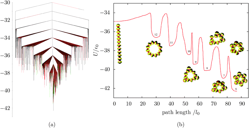
We have mapped the energy landscapes for two cluster sizes in detail, namely N = 12 and 26. Fig. 3a shows the disconnectivity graph constructed for the 12-particle cluster, εg = 0. The system has a well-defined global minimum, with some degree of frustration (low-energy kinetic traps corresponding to different morphologies). To rearrange from a misaligned structure to the global minimum, close contacts have to be broken and reformed, hence the relatively large barriers. This property is generic for the landscape of patchy particles with short-range attractive forces.To investigate the formation of the characteristic motif of Kagome structures (two staggered triangles), we characterised the fastest pathway (ignoring transition state recrossings) from a high-energy minimum, namely a linear chain of 12 particles. Fig. 3b shows the energy barriers and associated stationary points for this process. The 1D string bends to form a 12-membered planar ring, which then gradually shrinks through an overall downhill process, where high barriers are associated with the loss and subsequent formation of a close contact. Although the first three steps of the ring shrinking happen practically in the plane of the ring, subsequent loss of particles occurs out of the plane, involving cooperative deformation. This result is due to the ring becoming stiffer, so that more torsional strain is required to eject a particle from it (see Movie 1, ESI†). Clearly, if the system is not allowed to relax out of the plane, the energy barriers for the last three steps would become much higher.
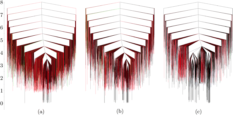
The disconnectivity graphs of the 12-particle (Fig. 3a) and 26-particle (Fig. 4) clusters show that structures with tetrahedral coordination are abundant on the landscape. In general, around a third of the explored structures contain particles in tetrahedral environments, when no gravity effects are considered. Once such effects are taken into account, however, structures containing tetrahedra become higher in energy compared to planar structures. Also, their relative abundance in the sampled region of the landscape decreases monotonically with increasing εg (Fig. 4). With larger gravitational effects, the ratio between the sampled minima containing one and two tetrahedral units increases: 13![[thin space (1/6-em)]](https://www.rsc.org/images/entities/char_2009.gif) :
:![[thin space (1/6-em)]](https://www.rsc.org/images/entities/char_2009.gif) 1 with no gravity, 26
1 with no gravity, 26![[thin space (1/6-em)]](https://www.rsc.org/images/entities/char_2009.gif) :
:![[thin space (1/6-em)]](https://www.rsc.org/images/entities/char_2009.gif) 1 with εg = 0.0165, and 232
1 with εg = 0.0165, and 232![[thin space (1/6-em)]](https://www.rsc.org/images/entities/char_2009.gif) :
:![[thin space (1/6-em)]](https://www.rsc.org/images/entities/char_2009.gif) 1 with εg = 0.165. Sedimentation therefore favours planar structures with two bonds per patch. In fact, gravity effects with εg = 0.165 are so strong that low-energy rearrangements involving planar structures occur only in the xy plane (see Movie 3, ESI†). Furthermore, minima containing five-membered rings introduce curvature in the structure for εg = 0 and 0.0165, but all such particles stay in plane for the largest gravity term considered. Example rearrangements are shown in the ESI.†
1 with εg = 0.165. Sedimentation therefore favours planar structures with two bonds per patch. In fact, gravity effects with εg = 0.165 are so strong that low-energy rearrangements involving planar structures occur only in the xy plane (see Movie 3, ESI†). Furthermore, minima containing five-membered rings introduce curvature in the structure for εg = 0 and 0.0165, but all such particles stay in plane for the largest gravity term considered. Example rearrangements are shown in the ESI.†
Although the landscape for 26 particles seems more frustrated than the one illustrated for 12 particles, every minimum within 0.5 energy units of the global minimum is in fact a Kagome structure with different configurations of the particles at the edges. In Fig. 4c, the two main funnels correspond to two Kagome structures that are flipped on the surface defined by the xy plane. These would be enantiomers in a 2D system.
4.3 Generalisations
Our building block design can be adapted for asymmetric patches as well, by shifting the position of the repulsive ellipsoid along the z axis. This change opens up the possibility of allowing different numbers of neighbours per patch, as well as different attraction strengths for each one. To strictly enforce one bond per patch at one pole of the particle, and only two bonds per patch at the other pole, it is necessary to increase the repulsion strength of the ellipsoid (εrep,A = 2), and decrease the interparticle distance for bonded configurations. The preferred ‘Y-shaped’ bonding pattern can be recreated with the following parameters: displacement along the z axis: 0.1, a11 = a12 = 1.5, a13 = 1.15, a21 = a22 = a23 = 1.3, and b21 = b22 = b23 = 1.38. The global minimum for 18 particles is a ring structure, part of a truncated hexagonal lattice, realized experimentally with asymmetrically grafted silica microspheres that sediment into monolayers.19 An interesting feature of this parameterisation is that the well depths for the two possible symmetric configurations of a dimer (large patch–large patch versus small patch–small patch) have a ratio of about 7.4![[thin space (1/6-em)]](https://www.rsc.org/images/entities/char_2009.gif) :
:![[thin space (1/6-em)]](https://www.rsc.org/images/entities/char_2009.gif) 1, so clusters of such building blocks will probably assemble in a hierarchical fashion, first forming trimers, which can then only bond by their small patches to form cyclic structures. In this particular system, the pentagonal arrangement of trimers is more favoured than the hexagonal one, therefore for N = 30, the global minimum is a chiral stacked dimer of pentagonal trimers instead of a planar structure of two fused hexagons, hinting at the possibility of another level of hierarchical self-organization.
1, so clusters of such building blocks will probably assemble in a hierarchical fashion, first forming trimers, which can then only bond by their small patches to form cyclic structures. In this particular system, the pentagonal arrangement of trimers is more favoured than the hexagonal one, therefore for N = 30, the global minimum is a chiral stacked dimer of pentagonal trimers instead of a planar structure of two fused hexagons, hinting at the possibility of another level of hierarchical self-organization.
Fig. 5 illustrates the predicted global minima for small clusters interacting with these asymmetric building blocks.
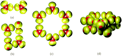 | ||
| Fig. 5 Predicted global minima of hierarchically organized clusters for asymmetric building blocks: (a) N = 6, (b) N = 12, (c) N = 18, (d) N = 30. | ||
Another model developed for soft triblock Janus particles35 investigated ordered packing in bulk, but did not report any configurations similar to Kagome lattices. It would be interesting to study the behaviour of that potential with sedimentation forces included, and explore the parameter space to see whether it is possible to form Kagome lattices from soft spherical building blocks. Our model has an anisotropic shape by design, and it is likely that the oblate overall shape of the particles contributes substantially to the stabilization of Kagome structures (and to the destabilization of close-packed structures).
5 Conclusions
We have presented what we believe to be the first unrestricted computational model that supports Kagome structures, using soft anisotropic triblock Janus particles. Kagome structures are global minima for small clusters with appropriate particle numbers. Our model allows more than two neighbours to be formed per patch, but tetrahedral environments are progressively disfavoured as sedimentation effects are increased. Additionally, we predict the formation of hollow structures obtained through bending of a Kagome lattice, in systems where sedimentation does not occur. The model, employing soft and continuous potentials, makes it possible to study large-scale rearrangements within the potential energy landscape framework,31,36 and we find that they are highly cooperative.The fact that no Kagome structures have been reported to date using unconstrained models of spherical particles with anisotropic interactions highlights the importance of sedimentation effects that restrict the available bonding patterns. We have shown that incorporating shape anisotropy and choosing somewhat longer range attractive interactions than those in current experimental systems makes it possible to stabilize the assembly of small clusters into Kagome structures even without sedimentation. The energetic stabilization of such clusters is enhanced when sedimentation occurs.
Acknowledgements
This research was financed by the European Union and the State of Hungary, co-financed by the European Social Fund in the framework of TÁMOP-4.2.4.A/2-11/1-2012-0001 ‘National Excellence Program’. DJW gratefully acknowledges support from the EPSRC and the ERC.References
- G. M. Whitesides and B. Grzybowski, Science, 2002, 295, 2418–2421 CrossRef CAS PubMed.
- B. A. Grzybowski, C. E. Wilmer, J. Kim, K. P. Browne and K. J. M. Bishop, Soft Matter, 2009, 5, 1110–1128 RSC.
- S. Zhang, Nat. Biotechnol., 2003, 21, 1171–1178 CrossRef CAS PubMed.
- B. Pelaz, S. Jaber, D. J. de Aberasturi, V. Wulf, T. Aida, J. M. de la Fuente, J. Feldmann, H. E. Gaub, L. Josephson, C. R. Kagan, N. A. Kotov, L. M. Liz-Marzan, H. Mattoussi, P. Mulvaney, C. B. Murray, A. L. Rogach, P. S. Weiss, I. Willner and W. J. Parak, ACS Nano, 2012, 6, 8468–8483 CrossRef CAS PubMed.
- S. C. Glotzer and M. J. Solomon, Nat. Mater., 2007, 6, 557–562 CrossRef PubMed.
- S. Sacanna, W. T. M. Irvine, P. M. Chaikin and D. J. Pine, Nature, 2010, 464, 575–578 CrossRef CAS PubMed.
- S. N. Fejer, D. Chakrabarti and D. J. Wales, Soft Matter, 2011, 7, 3553–3564 RSC.
- J. R. Wolters, G. Avvisati, F. Hagemans, T. Vissers, D. J. Kraft, M. Dijkstra and W. K. Kegel, Soft Matter, 2015, 11, 1067–1077 RSC.
- Q. Chen, S. C. Bae and S. Granick, Nature, 2011, 469, 381–384 CrossRef CAS PubMed.
- F. Romano and F. Sciortino, Soft Matter, 2011, 7, 5799–5804 RSC.
- N. Kern and D. Frenkel, J. Chem. Phys., 2003, 118, 9882–9889 CrossRef CAS PubMed.
- X. Mao, Q. Chen and S. Granick, Nat. Mater., 2013, 12, 217–222 CrossRef CAS PubMed.
- Y. Wang, Y. Wang, D. R. Breed, V. N. Manoharan, L. Feng, A. D. Hollingsworth, M. Weck and D. J. Pine, Nature, 2012, 491, 51–55 CrossRef CAS PubMed.
- L. Paramonov and S. N. Yaliraki, J. Chem. Phys., 2005, 123, 194111 CrossRef PubMed.
- S. N. Fejer, D. Chakrabarti and D. J. Wales, ACS Nano, 2010, 4, 219–228 CrossRef CAS PubMed.
- S. N. Fejer, D. Chakrabarti, H. Kusumaatmaja and D. J. Wales, Nanoscale, 2014, 6, 9448–9456 RSC.
- D. J. Wales, Philos. Trans. R. Soc., A, 2005, 363, 357–377 CrossRef CAS PubMed.
- D. Chakrabarti and D. J. Wales, Phys. Chem. Chem. Phys., 2009, 11, 1970–1976 RSC.
- Q. Chen, E. Diesel, J. K. Whitmer, S. C. Bae, E. Luijten and S. Granick, J. Am. Chem. Soc., 2011, 133, 7725–7727 CrossRef CAS PubMed.
- Z. Li and H. A. Scheraga, Proc. Natl. Acad. Sci. U. S. A., 1987, 84, 6611 CrossRef CAS.
- D. J. Wales and J. P. K. Doye, J. Phys. Chem. A, 1997, 101, 5111 CrossRef CAS.
- D. J. Wales and H. A. Scheraga, Science, 1999, 285, 1368–1372 CrossRef CAS.
- D. J. Wales, http://www-wales.ch.cam.ac.uk/software.html.
- D. J. Wales, Mol. Phys., 2002, 100, 3285–3306 CrossRef CAS PubMed.
- D. J. Wales, Mol. Phys., 2004, 102, 891–908 CrossRef CAS PubMed.
- D. J. Wales, Int. Rev. Phys. Chem., 2006, 25, 237–282 CrossRef CAS PubMed.
- S. A. Trygubenko and D. J. Wales, J. Chem. Phys., 2004, 120, 2082 CrossRef CAS PubMed.
- L. J. Munro and D. J. Wales, Phys. Rev. B: Condens. Matter Mater. Phys., 1999, 59, 3969–3980 CrossRef CAS.
- O. M. Becker and M. Karplus, J. Chem. Phys., 1997, 106, 1495–1517 CrossRef CAS PubMed.
- D. J. Wales, M. A. Miller and T. R. Walsh, Nature, 1998, 394, 758 CrossRef CAS.
- D. J. Wales, Curr. Opin. Struct. Biol., 2010, 20, 3–10 CrossRef CAS PubMed.
- S. T. Chill, J. Stevenson, V. Ruehle, C. Shang, P. Xiao, J. D. Farrell, D. J. Wales and G. Henkelman, J. Chem. Theory Comput., 2014, 10, 5476–5482 CrossRef CAS.
- K. Van Workum and J. F. Douglas, Phys. Rev. E: Stat., Nonlinear, Soft Matter Phys., 2006, 73, 1–17 CrossRef.
- M. A. Miller, J. J. Shepherd and D. J. Wales, Mol. Phys., 2008, 106, 1655–1664 CrossRef CAS PubMed.
- Z.-W. Li, Z.-Y. Lu, Y.-L. Zhu, Z.-Y. Sun and L.-J. An, RSC Adv., 2013, 3, 813–822 RSC.
- D. J. Wales, Energy Landscapes: Applications to Clusters, Biomolecules and Glasses, Cambridge University Press, 2003 Search PubMed.
Footnote |
| † Electronic supplementary information (ESI) available: Details on the scaling, supplementary figures and movies for rearrangements. See DOI: 10.1039/c5sm01191d |
| This journal is © The Royal Society of Chemistry 2015 |

