
 Open Access Article
 This Open Access Article is licensed under a
 Creative Commons Attribution 3.0 Unported Licence
Tunable dipolar capillary deformations for magnetic Janus particles at fluid–fluid interfaces
Qingguang
Xie
 a,
Gary B.
Davies
b,
Florian
Günther
a and
Jens
Harting
*ac
a,
Gary B.
Davies
b,
Florian
Günther
a and
Jens
Harting
*ac
aDepartment of Applied Physics, Eindhoven University of Technology, P.O. Box 513, NL-5600MB Eindhoven, The Netherlands. E-mail: q.xie1@tue.nl; f.s.guenther@tue.nl; j.harting@tue.nl
bCentre for Computational Science, University College London, 20 Gordon Street, London WC1H 0AJ, UK. E-mail: g.davies.11@ucl.ac.uk
cFaculty of Science and Technology, Mesa+ Institute, University of Twente, 7500 AE Enschde, The Netherlands
First published on 16th March 2015
Abstract
Janus particles have attracted significant interest as building blocks for complex materials in recent years. Furthermore, capillary interactions have been identified as a promising tool for directed self-assembly of particles at fluid–fluid interfaces. In this paper, we develop theoretical models describing the behaviour of magnetic Janus particles adsorbed at fluid–fluid interfaces interacting with an external magnetic field. Using numerical simulations, we test the models predictions and show that the magnetic Janus particles deform the interface in a dipolar manner. We suggest how to utilise the resulting dipolar capillary interactions to assemble particles at a fluid–fluid interface, and further demonstrate that the strength of these interactions can be tuned by altering the external field strength, opening up the possibility to create novel, reconfigurable materials.
I. Introduction
Colloidal Janus particles have drawn special attention during the past two decades for their potential in materials science.1 Janus particles are characterized by anisotropic surface chemical (e.g. wetting or catalytic) or physical (e.g. optical, electric, or magnetic) properties at well-defined areas on the particle. This combination of chemical anisotropy and response to external fields makes Janus particles promising building blocks of reconfigurable and programmable self-assembled structures.2–6Janus particles strongly adsorb at fluid–fluid interfaces,7 making the formation of 2D structures accessible. For symmetric Janus particles composed of hydrophobic and hydrophilic hemispheres, the equilibrium contact angle is 90° since each hemisphere immerses in its favourable fluid, and the interface remains flat.8 However, due to surface roughness,9 anisotropic shape,10,11 or the influence of external forces, Janus particles can tilt with respect to the interface. In a tilted orientation, the fluid–fluid interface around the Janus particle deforms in a dipolar fashion in order to fulfil boundary conditions stipulated by Young's equation.12 Assuming small interface deformations, the particle-induced interface deformations obey ∇2h = 0, where h is the interface height, which can be solved using a multipolar analysis, analagous to 2D electrostatics.13 These particle induced deformations, called capillary interactions, can cause particles to attract and repel in specific orientations, making them a useful tool for controlling the behaviour of particles at interfaces.
Previous investigations into capillary interactions between particles at fluid–fluid interfaces have focussed mainly around two themes: particle weight-induced deformations, which lead to monopolar interactions between particles and are responsible for e.g. the Cheerios effect;14 and surface roughness or shape anisotropy induced deformations, which lead to quadrupolar interactions between particles15 and are responsible for e.g. the suppression of the coffee ring effect.16 With respect to Janus particles, Brugarolas et al.17 showed that quadrupolar capillary interactions induced by surface roughness can be used to form fractal-like structures of Janus nanoparticle-shelled bubbles. However, a significant limitation of the above mentioned capillary interactions is that they are not dynamically tunable because they depend on the particle properties alone.
Davies et al.18 recently found a way of creating dynamically tunable dipolar capillary interactions between magnetic ellipsoidal particles adsorbed at an interface under the influence of an external magnetic field. The structures that form depend on the dipole-field coupling, which can be controlled dynamically.19 However, it is also desirable to create tunable capillary interactions between spherical particles without relying on particle shape anisotropy.
In this paper, we show how to create tunable dipolar capillary interactions using spherical Janus particles adsorbed at fluid–fluid interfaces. The Janus particles have a dipole moment orthogonal to their Janus boundary and are influenced by an external magnetic field directed parallel to the interface. The field causes the particles to experience a magnetic torque, but surface tension opposes this torque, and the particles therefore tilt with respect to the interface. When tilted, the particles deform the interface in a dipolar fashion.
We develop a free energy based model of the behaviour of a single particle at the interface, and a model which takes into account small interface deformations. We numerically investigate the predictions of the models using lattice Boltzmann simulations and highlight that the dipolar interface deformations lead to novel and interesting particle behaviour at the interface. Finally, we explain how to use these interface deformations to manufacture tunable capillary interactions between many particles at a fluid–fluid interface, which could be utilised to assemble reconfigurable materials.
This paper is organised as follows. We present our hybrid molecular dynamics-lattice Boltzmann simulation method in Section II. In Section III, we develop two theoretical models describing the behaviour of Janus particles at fluid–fluid interfaces. Section IV contains our simulation results, and we compare these results with our theoretical models from Section III. Finally, Section V concludes the article.
II. Simulation method
A. The multicomponent lattice Boltzmann method
We use the lattice Boltzmann method (LBM) to simulate the motion of each fluid. The LBM is a local mesoscopic algorithm, allowing for efficient parallel implementations, and has demonstrated itself as a powerful tool for numerical simulations of fluid flows.20 It has been extended to allow the simulation of, for example, multiphase/multicomponent fluids21,22 and suspensions of particles of arbitrary shape and wettability.23–25We implement the pseudopotential multicomponent LBM method of Shan and Chen21 with a D3Q19 lattice26 and review some relevant details in the following. For a detailed description of the method, we refer the reader to the relevant literature.24,25,27–29 Two fluid components are modelled by following the evolution of each distribution function discretized in space and time according to the lattice Boltzmann equation:
 | (1) |
![[x with combining right harpoon above (vector)]](https://www.rsc.org/images/entities/i_char_0078_20d1.gif) ,t) are the single-particle distribution functions for fluid component c = 1 or 2,
,t) are the single-particle distribution functions for fluid component c = 1 or 2, ![[c with combining right harpoon above (vector)]](https://www.rsc.org/images/entities/i_char_0063_20d1.gif) i is the discrete velocity in ith direction, and τc is the relaxation time for component c. The macroscopic densities and velocities are defined as
i is the discrete velocity in ith direction, and τc is the relaxation time for component c. The macroscopic densities and velocities are defined as 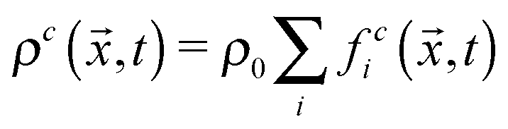 , where ρ0 is a reference density, and
 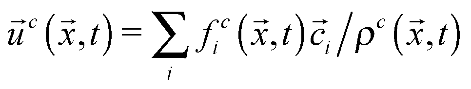 , respectively. Here, feqi(ρc(,t),
![[u with combining right harpoon above (vector)]](https://www.rsc.org/images/entities/i_char_0075_20d1.gif) c(,t)) is a third-order equilibrium distribution function. When sufficient lattice symmetry is guaranteed, the Navier–Stokes equations can be recovered from eqn (1) on appropriate length and time scales.20 For convenience we choose the lattice constant Δx, the timestep Δt, the unit mass ρ0 and the relaxation time τc to be unity, which leads to a kinematic viscosity
c(,t)) is a third-order equilibrium distribution function. When sufficient lattice symmetry is guaranteed, the Navier–Stokes equations can be recovered from eqn (1) on appropriate length and time scales.20 For convenience we choose the lattice constant Δx, the timestep Δt, the unit mass ρ0 and the relaxation time τc to be unity, which leads to a kinematic viscosity  in lattice units.
The Shan–Chen multicomponent model introduces a mean-field interaction force
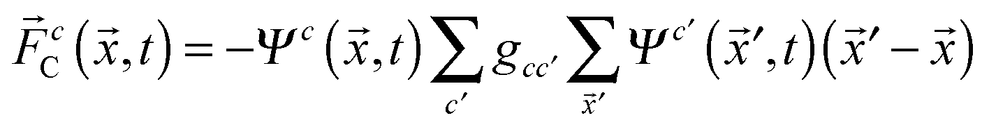 | (2) |
′ denote the nearest neighbours of lattice site and gcc′ is a coupling constant determining the surface tension. Ψc(x,t) is an “effective mass”, chosen with the following functional form: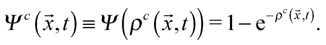 | (3) |
 to the velocity c(,t) in the equilibrium distribution. The Shan–Chen LB method is a diffuse interface method, resulting in an interface width of ≈5Δx.27
B. The colloidal particle
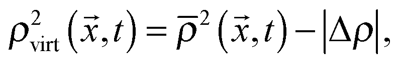
The trajectory of the colloidal Janus particle is updated using a leap-frog integrator. The particle is discretized on the fluid lattice and coupled to the fluid species by means of a modified bounce-back boundary condition as pioneered by Ladd and Aidun.23,30The outer shell of the particle is filled with a “virtual” fluid with the density
 | (4) |
 | (5) |
 and
and  are the average of the density of neighbouring fluid nodes for component 1 and 2, respectively. The parameter Δρ is called the “particle colour” and dictates the contact angle of the particle. A particle colour Δρ = 0 corresponds to a contact angle of θ = 90°, i.e. a neutrally wetting particle. In order to simulate a Janus particle, we set different particle colours in well defined surface areas corresponding to the different hemispheres of the particle.
We choose a system size S = 128 × 64 × 128 to eliminate finite size effects. We fill one half of the system with fluid 1 and the other half with fluid 2 of equal density (ρ1 = ρ2 = 0.7) such that a fluid–fluid interface forms at y = 32. The interaction strength in eqn (2) is chosen to be g12 = 0.1 and the particle with radius R = 10 is placed at the interface. We impose walls with mid-grid bounce back boundary conditions at the top and bottom of the system parallel to the interface, while all other boundaries are periodic.
III. Theoretical results
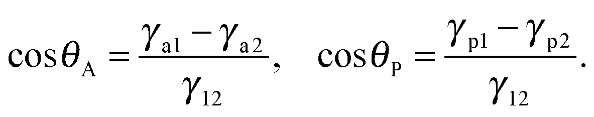
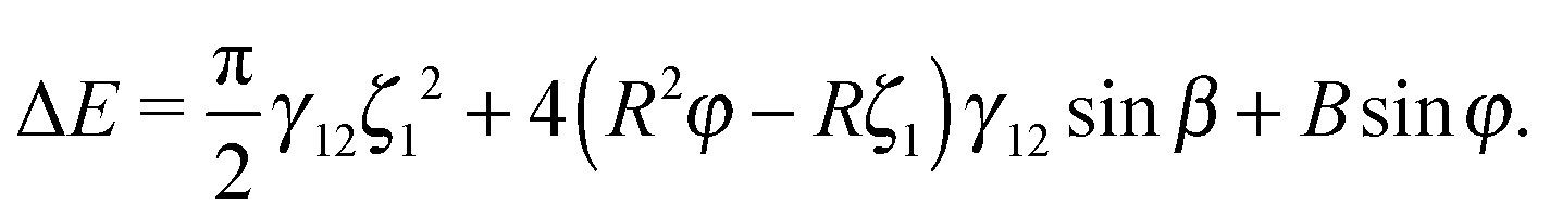
We consider a spherical Janus particle composed of apolar and polar hemispheres adsorbed at a fluid–fluid interface, as illustrated in Fig. 1a. The two hemispheres have opposite wettability, represented by the three-phase contact angles θA = 90° + β and θP = 90° − β, respectively, where β represents the amphiphilicity of the particle. A larger β value corresponds to a greater degree of particle amphiphilicity. In its equilibrium state, the Janus particle takes an upright orientation with respect to the interface with its two hemispheres totally immersed in their favourable phases, as shown in Fig. 1a.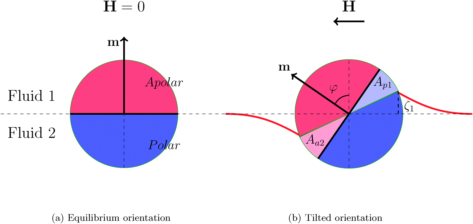 | ||
| Fig. 1 A single Janus particle adsorbed at a fluid–fluid interface in its equilibrium orientation (a) and in a tilted orientation (b). The Janus particle consists of an apolar and a polar hemisphere. The particle's magnetic dipole moment m is orthogonal to the Janus boundary, and the external magnetic field, H, is directed parallel to the interface. The tilt angle φ is defined as the angle between the particle's dipole moment and the undeformed interface normal. Aa2 and Ap1 are the surface areas of the apolar hemisphere immersed in fluid 2 and the polar hemisphere immersed in fluid 1, respectively. The bold red line represents the deformed interface and ζ1 is the maximal interface height at the contact line. | ||
The free energy of the particle in its equilibrium configuration is
| Eint = γ12Aint12 + γa1Ainta1 + γp2Aintp2, | (6) |
After switching on the horizontal magnetic field, H, the particle experiences a torque t = m × H that attempts to align the particle dipole axis with the field. However, surface tension resists the rotation causing the particle to tilt with respect to the interface for a given dipole-field strength B = |m||H|, as illustrated in Fig. 1b. The tilt angle φ is defined as the angle between particle dipole-moment and the undeformed interface normal (i.e. the y-axis). The interface deforms around the particle so that each fluid contacts a larger area of its favourable particle surface (Fig. 1b). This interface deformation increases the fluid–fluid interface area and decreases the surface of each hemisphere contacting its unfavourable fluid. The free energy of the system is reduced in total due to the dominant contribution of particle-fluid interface energies.12 The free energy of a Janus particle in a tilted orientation can be written as
Etilt = γ12Atilt12 + γa1Atilta1 + γp2Atiltp2 + γa2Aa2 + γp1Ap1 + B![[thin space (1/6-em)]](https://www.rsc.org/images/entities/char_2009.gif) sinφ. sinφ. | (7) |
| ΔE = Etilt − Eint = γ12(Atilt12 − Aint12) + γa1(Atilta1 − Ainta1) + γp2(Atiltp2 − Aintp2) + γa2Aa2 + γp1Ap1 + Bsinφ. | (8) |
| ΔE = γ12ΔA12 + (γa2 − γa1)Aa2 + (γp1 − γp2)Ap1 + Bsinφ, | (9) |
 | (10) |
θA = −cosθP = −sinβ. Eqn (9) is further simplified to| ΔE = γ12ΔA12 + γ12(Aa2 + Ap1)sinβ + Bsinφ. | (11) |
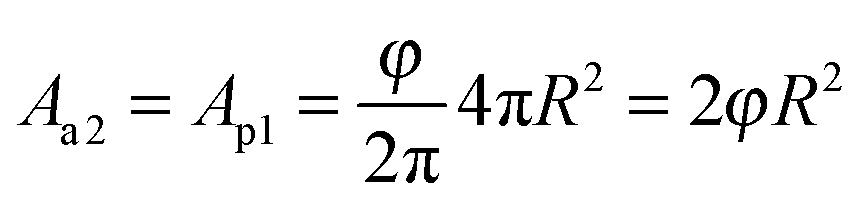 . Therefore, eqn (9) finally reduces to
| ΔE = 4φR2γ12sinβ + Bsinφ. | (12) |
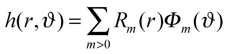
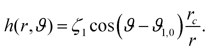
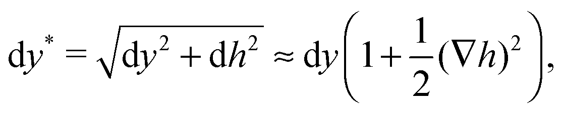
There is no exact analytical expression for the free energy of a tilted Janus particle at an interface that includes interface deformations, due to the difficulty in modelling the shape of the interface and position of the contact line. However, in the limit of small interface deformations,13 we derive such an analytical expression for the free energy.
We consider micron-sized particles with a radius much smaller than the capillary length such that we can neglect the effect of gravity. We assume the pressure drop across the interface to be zero, leading to vanishing mean curvature according to the Young–Laplace equation. The mean curvature can be approximately written in cylindrical coordinates as13
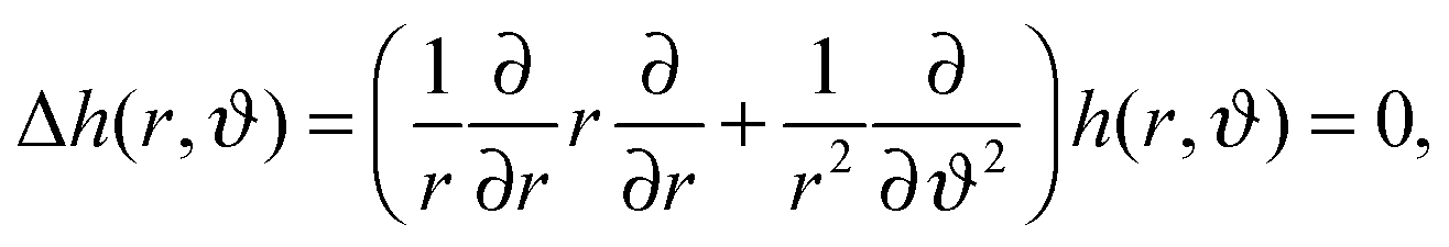 | (13) |
 | (14) |
 | (15) |
 | (16) |
| dx* = dx, | (17) |
 | (18) |
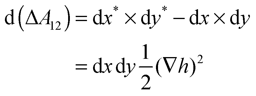 | (19) |
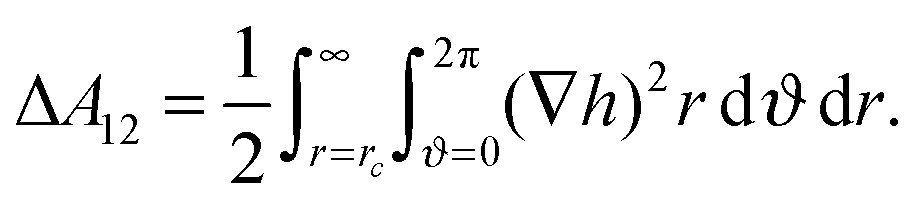 | (20) |
 | (21) |
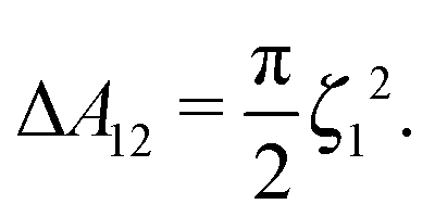 | (22) |
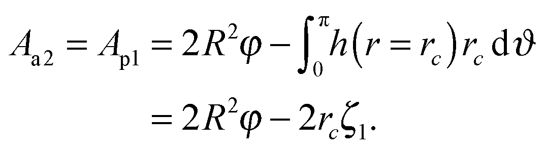 | (23) |
 | (24) |
IV. Simulation results and comparison to theory
In addition to the theoretical models we developed in Section III, we numerically calculate the free energy of a single Janus particle adsorbed at a fluid–fluid interface using lattice Boltzmann simulations. Our lattice Boltzmann simulations are capable of capturing interface deformations fully without making any assumptions about the magnitude of the deformations or stipulating any particle-fluid boundary conditions.Fig. 2a shows the initial equilibrium configuration of our Janus particle simulation, where each hemisphere totally immerses in its corresponding favourable liquid so that the interface remains flat. Fig. 2b shows how the three-phase contact line and interface deform around the Janus particle as it tilts with respect to the interface.
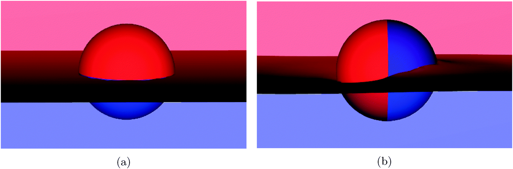 | ||
| Fig. 2 Snapshots of a Janus particle at a fluid–fluid interface at (a) initial equilibrium state (φ = 0°) and (b) tilted orientation state (φ = 90°) as obtained from our simulations. The three-phase contact line undulates around the tilted particle so that the interface is deformed. | ||
In order to obtain the free energy of the Janus particle as a function of tilt angle from our simulations, the total surface area of the deformed fluid–fluid interface and the corresponding particle surfaces have to be measured.12,18,31 In this paper, we employ a simple method, which utilises the ability to easily measure the force applied to the particle by the fluids using the lattice Boltzmann method.
We first determine the contribution to the free energy neglecting the dipole-field contributions by integrating the torque on the particle as the particle rotates quasi-statically,
 | (25) |
Fig. 3 shows the evolution of this torque τφversus the tilt angle for different amphiphilicities β = 21° (circles), β = 30° (triangles), and β = 39° (diamonds), corresponding to particle colours Δρ = 0.10, 0.15, 0.20, respectively. For all amphiphilicities, the torque increases linearly as the particle rotates for small tilt angles, φ < 30°. As the tilt angle increases further φ → 90° the torque tends to a nearly constant value. We fit the torque τφ with a hyperbolic tangent function, and integrate the fitted function numerically to obtain the free energy.
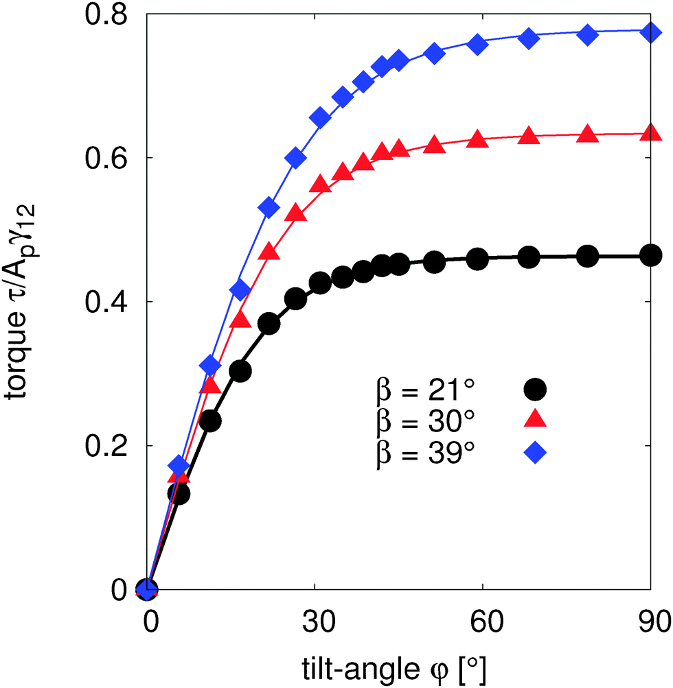 | ||
| Fig. 3 Reduced torque τ/Apγ12 as a function of tilt angle φ for β = 21° (circles), β = 30° (triangles) and β = 39° (diamonds), where Ap = πR2. The symbols are simulation data and the solid lines represent hyperbolic tangent functions to fit the data. The fitted functions are integrated in order to obtain the free energy. For all amphiphilicities, the torque is linear for small rotations around the equilibrium position, before reaching a constant value at very large tilt angles φ → 90°. | ||
In order to calculate the free energy of our small interface deformation based model (eqn (24)), we measure the corresponding maximal height of the contact line ζ1 as a function of tilt angle, as shown in Fig. 4. Similarly to Fig. 3, the height of the contact line increases linearly for small tilt angles, and then reaches a plateau for large tilt angles. The height plateau demonstrates that the deformed interface area remains constant at large tilt angles. This indicates that at large tilt angles, only the particle-fluid surface energy, which increases linearly with increasing tilt angle, contributes to the change in free energy, and therefore the torque τ ∝ d(ΔE)/dφ is constant at large tilt angles, in agreement with Fig. 3.
 | ||
| Fig. 4 Reduced maximal height of the deformed interface ζ1/R as a function of tilt angle φ for β = 21° (circles), β = 30° (triangles) and β = 39° (diamonds). The data (symbols) are fitted with a hyperbolic tangent function (solid lines). The maximal interface height increases linearly with tilt angle for small angles, and becomes constant for large angles. | ||
In Fig. 5 we compare the free energy models that we developed in Section III assuming no interface deformations (eqn (12), dashed lines) and small interface deformations (eqn (24), solid lines) with our lattice Boltzmann simulation data (symbols), which incorporates interface deformation fully, by measuring the free energies as a function of particle tilt angle as described above.
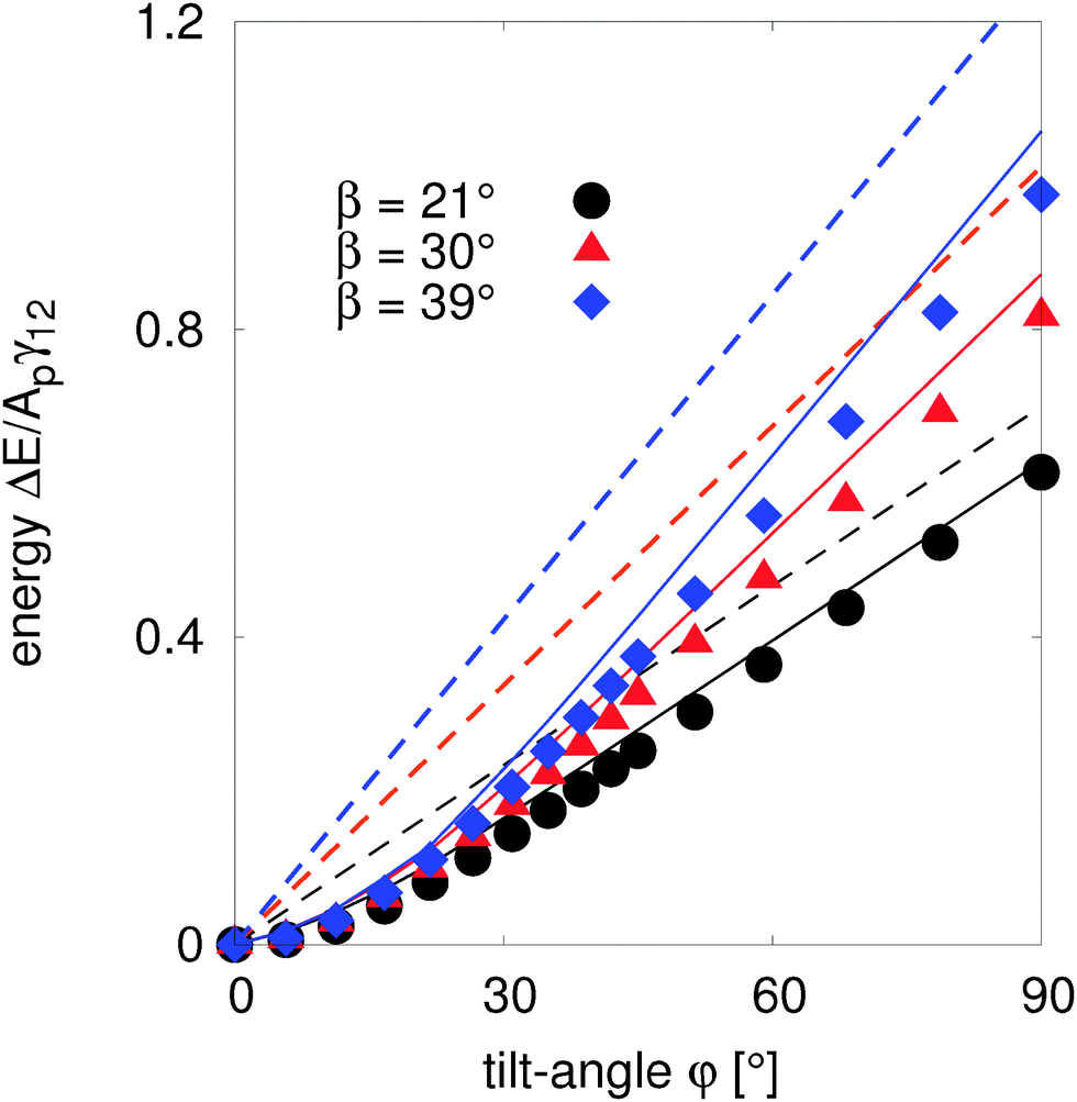 | ||
| Fig. 5 Free energy as a function of tilt angle φ for β = 21° (circles), β = 30° (triangles) and β = 39° (diamonds), which are calculated using the analytical model that excludes interface deformations (eqn (12), dashed lines), our analytical model which assumes small interface deformations (eqn (24), solid lines) and numerically integrated results (symbols) without considering a magnetic dipole-field contribution (B = 0). The undeformed interface model eqn (12) shows non-negligible deviation from the simulation data. For small β and small φ, the small deformation model eqn (24) is in good agreement with the simulation results. | ||
Our undeformed interface model (eqn (12)) predicts that the energy varies linearly with the particle tilt angle, φ, for all particle amphiphilicities, β = 21°, 30°, and 39°. The model also predicts that the free energy increases as the amphiphilicity increases from β = 21° to β = 39° for any given tilt angle. Our analytical model assuming small interface deformations (eqn (24)) shows some interesting qualitative behaviour. Firstly, for small tilt angles, φ < 30°, the energy varies quadratically with the tilt angle for all amphiphilicities. This is because for small tilt angles, the maximal interface height ζ1 varies linearly with the tilt angle (Fig. 4), ζ1 ≈ Rφ, and the free energy in eqn (24) becomes approximately  .
.
Secondly, for larger tilt angles, φ > 45°, the energy varies linearly with the tilt angle, due to the fact that for large angles, ζ1 is constant (Fig. 4). Therefore, eqn (24) becomes ΔE = 4R2γ12sinβφ + C, where C is a constant, which explains the linear behaviour of the free energy for large tilt angles.
The above analysis also explains why, for tilt angles φ < 30°, the energy only weakly depends on the amphiphilicity β of the particles: the amphiphilicity term sinβ is only significant for large tilt angles.
When comparing these two models with our simulation data (symbols), we find that the small deformation model captures the qualitative features of the data extremely well. In addition, the model quantitatively agrees with the numerical results for small tilt angles φ < 30° for all amphiphilicities. As the tilt angle of the particles increases the quantitative deviation between the model and the data becomes more significant. However, for small amphiphilicities β = 21° the model and numerical data are in good agreement.
In contrast, our theoretical model that takes into account only the free energy differences between the particle as a function of its orientation and therefore neglects interface deformations (eqn (12)) performs much worse. The model captures the qualitative linear behaviour of the numerical data only for large tilt angles φ > 50°, but with large quantitative differences that increase as the particle amphiphilicity increases. The results in Fig. 5 clearly show that interface deformations strongly affect the behaviour of a tilted Janus particle adsorbed at a fluid–fluid interface, and we note that our analytical model that includes small interface deformations is clearly able to capture this qualitative behaviour.
To verify the predictions of the analytical models including dipole-field contributions, we switch on the magnetic field and numerically measure the tilt angle of the particle after the system has equilibrated, as per eqn (25). We obtain the tilt angle as a function of the dipole-field strength by minimizing the free energies in eqn (12) and (24) with respect to the tilt angle.
In Fig. 6, we compare the predicted tilt angles from the free energy models assuming no interface deformation (eqn (12), dashed lines) and small interface deformation (eqn (24), solid lines) with our numerical simulation data (symbols), which incorporates interface deformation fully, by measuring the tilt angle as a function of dipole-field strength, for β = 21°, 30°, and β = 39°.
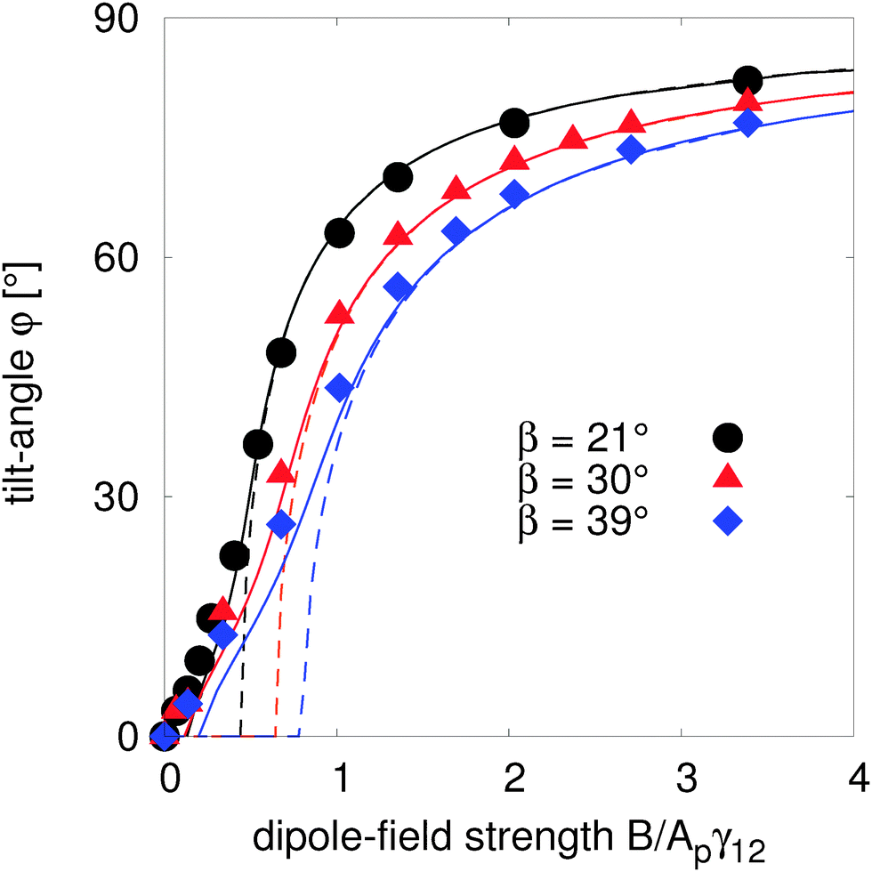 | ||
| Fig. 6 Tilt angle φ as a function of dipole-field strength for different amphiphilicities β = 21° (circles), β = 30° (triangles) and β = 39° (diamonds). We compare the simulation data (symbols) with the tilted angles predicted using the analytical model which excludes interface deformations (eqn (12), dashed lines), and our analytical model which assumes small interface deformations (eqn (24), solid lines). For small dipole-field strengths, the tilt angle predicted by the undeformed interface model shows large deviations from the simulation data, whereas the tilt angle obtained from the small deformation model agrees well with the simulations. | ||
For large dipole-field strengths B > 1.5Apγ12, both analytical models perform well by predicting the numerically measured tilt angles for all particle amphiphilicities β. This is due to the fact that large dipole-field strengths cause large tilt angles at which the deformed interface area stops increasing, as shown in Fig. 4. In this regime, the equilibrium orientation only depends on the particle properties (radius R and amphiphilicity β), interface tension γ12, and dipole-field strength B, which are incorporated into both analytical models.
For small dipole-field strengths, the tilt angle predicted by the undeformed interface model eqn (12) shows large deviations from the simulation data for all amphiphilicities. The deviations increase with increasing particle amphiphilicity. In addition, the undeformed interface model predicts a large critical dipole-field strength at which the particle begins to rotate, which we do not observe in the simulations. This critical dipole-field strength increases with increasing particle amphiphilicity. From eqn (12), we can obtain the torque, 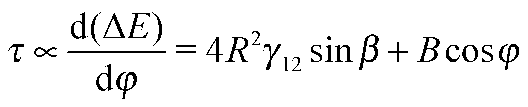 where the first term is independent of the tilt angle φ. Therefore, in the zero dipole-field state φ = 0°, a critical dipole-field strength Bc = 4R2γ12sinβ is needed to overcome this constant resistive component of the torque.
Our small deformation model (eqn (24)) shows significant improvement at predicting the tilt angle compared with the undeformed interface model. The predicted tilt angle from this model shows good agreement with simulation data for weak dipole-field strengths, especially for amphiphilicity β = 21°. In particular the model predicts a much smaller, though still finite, critical dipole-field strength, agreeing better with our numerical simulations. We conclude that interface deformations strongly affect the orientation of a tilted Janus particle adsorbed at a fluid–fluid interface.
Finally, Fig. 7 shows that the Janus particle deforms the interface in a dipolar fashion: a symmetric depression and rise on opposite sides of the particle, as also shown in Fig. 2b. Since the strength of the capillary interactions between two particles interacting as polar capillary dipoles depends on the maximal interface deformation height ζ1, we can tune the strength of capillary interactions by varying the dipole-field strength. These unique dipolar capillary interactions may be used to assemble particles into novel materials at a fluid–fluid interface in a tunable way.19
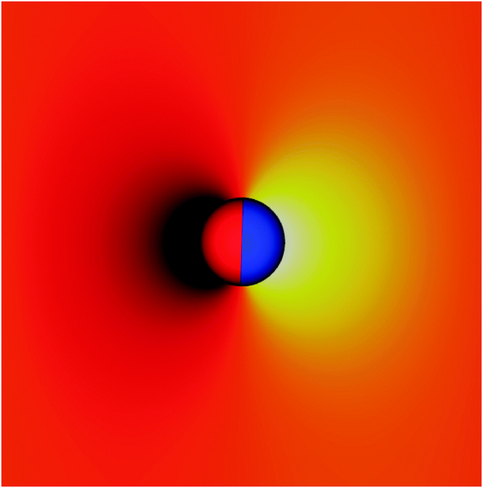 | ||
| Fig. 7 Plot of the relative height of the interface. Influenced by a magnetic torque, the Janus particle reorients, leading to dipolar interface deformations: the interface is depressed on one side of particle (black) and raised on the other side (yellow). The interface is flat in the orange/red regions. These dipolar interface deformations are dynamically tunable, providing a route to generate tunable capillary-driven assembly at fluid interfaces. | ||
V. Conclusion
We studied the behaviour of a magnetic spherical amphiphilic Janus particle adsorbed at a fluid–fluid interface under the influence of an external magnetic field directed parallel to the interface.The interaction of the particle with the external field results in a torque that tilts the particle, introducing interface deformation. We derived analytical models assuming no interface deformations and small interface deformations that enable the calculation of the free energy, ΔE, and hence the equilibrium orientation φ, of the particle in terms of the particle size R, particle amphiphilicity β, fluid–fluid interface tension γ12, maximal interface height ζ1, and magnetic dipole-field strength B. We used lattice Boltzmann simulations that incorporate interface deformations fully to test the results of our analytical models.
In the absence of a magnetic field, our simulations showed that the maximal interface deformation height ζ1 increases linearly ζ1 ≈ Rψ for small tilt angles and then reaches a plateau for large tilt angles ζ1 ≈ const. They also showed that the free energy of the particle increases quadratically for small tilt angles and linearly for large tilt angles. We explain this behaviour in terms of our theoretical model assuming small interface deformations that correctly predicts this behaviour, and find that the free energy varies approximately as  for small tilt angles and as ΔE = 4R2γ12sinβφ + C for large tilt angles.
With the magnetic field switched on, we calculated the dependence of the tilt angle φ, on the dipole-field strength B, by minimising the calculated free energies with respect to the tilt angle φ, for a given dipole-field strength B.
Our undeformed interface model based on free energy differences agrees qualitatively with our simulation results only for large particle tilt angles, but deviates significantly quantitatively. In particular, this model predicts a critical dipole-field strength Bc = 4R2γ12sinβ in order to rotate the particle, which we do not observe in our simulations. Our results contrast with other free energy difference based models that assume a flat interface, which were able to predict the equilibrium orientation of nanoparticles reasonably accurately.10,11
Our analytical model that includes small interface deformations captures the qualitative behaviour of the particle well for all tilt angles, and also performs well quantitatively, in particular for small particle amphiphilicities β. Previous studies by Davies et al.18 have shown that interface deformations can significantly alter the quantitative behaviour of ellipsoidal particles at interfaces, however, our results demonstrate that interface deformations can both quantitatively and qualitatively affect the behaviour of Janus particles at fluid–fluid interfaces and therefore cannot be neglected.
Finally, we show that the interface deformations around a spherical magnetic titled Janus particle influenced by an external field directed parallel to the interface are dipolar in nature. Further, we demonstrate that the magnitude of these deformations can be dynamically tuned, and therefore the capillary interactions between monolayers of such particles are tunable, and we suggest that this may enable the production of novel, reconfigurable materials.
Acknowledgements
Financial support is acknowledged from NWO/STW (Vidi grant 10787 of J. Harting and STW project 13291). We thank the Jülich Supercomputing Centre and the High Performance Computing Center Stuttgart for the technical support and the CPU time which was allocated within grants of the Gauss Center for Supercomputing and the “Partnership for Advanced Computing” (PRACE). GBD acknowledges Fujitsu and EPSRC for funding.References
- P. G. de Gennes, Rev. Mod. Phys., 1992, 64, 645 CrossRef.
- A. Walther and A. H. E. Müller, Chem. Rev., 2013, 113, 5194 CrossRef CAS PubMed.
- J. Yan, M. Bloom, S. C. Bae, E. Luijten and S. Granick, Nature, 2012, 491, 578 CrossRef CAS PubMed.
- S. K. Smoukov, S. Gangwal, M. Marquez and O. D. Velev, Soft Matter, 2009, 5, 1285 RSC.
- B. Ren, A. Ruditskiy, J. H. Song and I. Kretzschmar, Langmuir, 2012, 28, 1149 CrossRef CAS PubMed.
- A. Ruditskiy, B. Ren and I. Kretzschmar, Soft Matter, 2013, 9, 9174 RSC.
- B. P. Binks and P. D. I. Fletcher, Langmuir, 2001, 17, 4708 CrossRef CAS.
- T. Ondarcuhu, P. Fabre, E. Raphaël and M. Veyssié, J. Phys., 1990, 51, 1527 Search PubMed.
- D. J. Adams, S. Adams, J. Melrose and A. C. Weaver, Colloids Surf., A, 2008, 317, 360 CrossRef CAS PubMed.
- B. J. Park and D. Lee, ACS Nano, 2012, 6, 782 CrossRef CAS PubMed.
- B. J. Park and D. Lee, Soft Matter, 2012, 8, 7690 RSC.
- H. Rezvantalab and S. Shojaei-Zadeh, Soft Matter, 2013, 9, 3640 RSC.
- D. Stamou, C. Duschl and D. Johannsmann, Phys. Rev. E: Stat. Phys., Plasmas, Fluids, Relat. Interdiscip. Top., 2000, 62, 5263 CrossRef CAS.
- D. Vella and L. Mahadevan, Am. J. Phys., 2005, 73, 817 CrossRef.
- J. C. Loudet, A. M. Alsayed, J. Zhang and A. G. Yodh, Phys. Rev. Lett., 2005, 94, 018301 CrossRef CAS.
- P. J. Yunker, T. Still, M. A. Lohr and A. G. Yodh, Nature, 2011, 476, 308 CrossRef CAS PubMed.
- T. Brugarolas, B. J. Park, M. H. Lee and D. Lee, Adv. Funct. Mater., 2011, 21, 3924 CrossRef CAS.
- G. B. Davies, T. Krüger, P. V. Coveney, J. Harting and F. Bresme, Soft Matter, 2014, 10, 6742 RSC.
- G. B. Davies, T. Krüger, P. V. Coveney, J. Harting and F. Bresme, Adv. Mater., 2014, 26, 6715 CrossRef CAS PubMed.
- S. Succi, The Lattice Boltzmann Equation for Fluid Dynamics and Beyond, Oxford University Press, 2001 Search PubMed.
- X. Shan and H. Chen, Phys. Rev. E: Stat. Phys., Plasmas, Fluids, Relat. Interdiscip. Top., 1993, 47, 1815 CrossRef.
- S. Cappelli, Q. Xie, J. Harting, A. M. Jong and M. W. J. Prins, New Biotechnol., 2015 DOI:10.1016/j.nbt.2015.02.010.
- A. J. C. Ladd and R. Verberg, J. Stat. Phys., 2001, 104, 1191 CrossRef CAS.
- F. Jansen and J. Harting, Phys. Rev. E: Stat., Nonlinear, Soft Matter Phys., 2011, 83, 046707 CrossRef.
- F. Günther, F. Janoschek, S. Frijters and J. Harting, Comput. Fluids, 2013, 80, 184 CrossRef PubMed.
- Y. H. Qian, D. D'Humières and P. Lallemand, Europhys. Lett., 1992, 17, 479 CrossRef.
- S. Frijters, F. Günther and J. Harting, Soft Matter, 2012, 8, 6542 RSC.
- F. Günther, S. Frijters and J. Harting, Soft Matter, 2014, 10, 4977 RSC.
- S. Frijters, F. Günther and J. Harting, Phys. Rev. E: Stat., Nonlinear, Soft Matter Phys., 2014, 90, 042307 CrossRef.
- C. K. Aidun, Y. Lu and E.-J. Ding, J. Fluid Mech., 1998, 373, 287 CrossRef CAS.
- S. Dasgupta, M. Katava, M. Faraj, T. Auth and G. Gompper, Langmuir, 2014, 30, 11873 CrossRef CAS PubMed.
| This journal is © The Royal Society of Chemistry 2015 |