
Shape transformations of toroidal vesicles†
Hiroshi
Noguchi
*a,
Ai
Sakashita
ab and
Masayuki
Imai
c
aInstitute for Solid State Physics, University of Tokyo, Kashiwa, Chiba 277-8581, Japan. E-mail: noguchi@issp.u-tokyo.ac.jp
bDepartment of Physics, Ochanomizu University, 2-1-1 Otsuka, Bunkyo, Tokyo 112-8610, Japan
cDepartment of Physics, Faculty of Science, Tohoku University, 6-3 Aramaki, Aoba-ku, Sendai, Miyagi 980-8578, Japan
First published on 17th October 2014
Abstract
Morphologies of genus-1 and 2 toroidal vesicles are studied numerically by dynamically triangulated membrane models and experimentally by confocal laser microscopy. Our simulation results reproduce shape transformations observed in our experiments well. At large reduced volumes of the genus-1 vesicles, obtained vesicle shapes agree with the previous theoretical prediction, in which axisymmetric shapes are assumed: double-necked stomatocyte, discoidal toroid, and circular toroid. However, for small reduced volumes, it is revealed that a non-axisymmetric discoidal toroid and handled discocyte exist in thermal equilibrium in the parameter range, in which the previous theory predicts axisymmetric discoidal shapes. Polygonal toroidal vesicles and subsequent budding transitions are also found. The entropy caused by shape fluctuations slightly modifies the stability of the vesicle shapes.
1 Introduction
Vesicles are closed bilayer membranes that show a wide variety of morphologies depending on the lipid architecture as well as their environment. Since fluid lipid membranes are the main component of biomembranes, lipid vesicles are considered as a simple model system of cells. In particular, vesicle shapes with genus g = 0 have been intensively investigated and are well understood.1–9 For example, the shape of red blood cells, discocyte, can be formed by a lipid membrane without proteins. In contrast to the genus-0 vesicles, vesicles with nonzero genus have been much less explored. In this paper, we focus on vesicles with g = 1 and g = 2.In living cells, organelles exist in various shapes. In some organelles, lipidic necks or pores connect biomembranes such that they have nonzero genus. For example, the nuclear membrane and endoplasmic reticulum are connected and together form complicated shapes. The nucleus is wrapped by two bilayer membranes connected by many lipidic pores. Thus, its shape is considered as a stomatocyte of a high-genus vesicle connected with a tubular network. It is important to understand how their topologies affect their morphologies.
Vesicle shapes are determined by the curvature energy and the area difference ΔA of two monolayers of bilayer membranes with a constraint on the reduced volume V*,1–4 which is the volume relative to a spherical vesicle of the same surface area. It is defined as V* = V/(4π/3)RA3 with  , where V and A are the vesicle volume and surface area, respectively. Since transverse diffusion (flip–flop) of phospholipids between two monolayers is very slow, the number difference ΔNlip of lipids between two monolayers can be conserved on a typical experimental time scale. In the bilayer coupling (BC) model, the area difference ΔA is fixed as the preferred value ΔA0 = ΔNlipalip, where alip is the area per lipid in tensionless membranes. In the area-difference–elasticity (ADE) model, a harmonic potential for the difference ΔA − ΔA0 is added as a penalty for the deviation of the area difference. For genus-0 vesicles, various observed morphologies can be reproduced well by both BC and ADE models:1–4 stomatocyte, discocyte, prolate, pear, pearl-necklace, and branched starfish-like shapes. However, shape-transformation dynamics is better explained by the ADE model.8
The vesicle shapes with g = 1 and g = 2 were studied in the 1990s.10–18 For g = 1, the phase diagrams of axisymmetric shapes were constructed for the BC, ADE, and spontaneous-curvature models by Jülicher et al.13 They assumed axisymmetry of the vesicle shape and the region of non-axisymmetric shapes is only estimated by a stability analysis of the axisymmetric shapes. However, the stability is only examined with respect to special conformal transformations and non-axisymmetric shapes were not directly explored. Thus, the full phase diagram of genus-1 vesicles has not been completed. For g = 2, conformational degeneracy was found in the ground state at V* ≳ 0.7, where the vesicles can transform their shapes without changing their curvature energy with fixed V* and ΔA.14,15,17 In this paper, we revisit the phase diagram of g = 1 using three-dimensional simulations and find non-axisymmetric thermal-equilibrium shapes in the region where axisymmetric shapes were assumed in ref. 13. In all of the previous theoretical studies on non-zero genus vesicles, the thermal fluctuations were neglected. However, experimentally, neck diffusion of toroidal vesicles and bending and length fluctuations of lipid tubes were reported.16,19,20 We also investigate the effects of thermal fluctuations and compare our simulation results with shape transformations observed in our experiments for g = 1 and 2.
The simulation and experimental methods are provided in Section 2. In Section 3.1, vesicle shapes at g = 1 are described. First, the stable states for the curvature energy without the bilayer-coupling constraint or ADE energy are explained as a starting point. Subsequently the free-energy profiles are calculated for three values of the reduced volume. This calculation clarifies discrete shape transitions from non-axisymmetric discoidal shapes to circular toroids in the ADE model. The simulation results are compared with experimental images. The budding transitions are also discussed. In Section 3.2 the results for g = 2 are described. The summary and conclusions are given in Section 4.
2 Materials and methods
2.1 Dynamically triangulated membrane model
We employ a dynamically triangulated surface model to describe a fluid membrane.7,21,22 The vesicle consists of Nmb vertices connected by bonds (tethers) to form a triangular network. The vertices have a hard-core excluded volume of diameter σ0. The maximum length of the bond is σ1. In order to keep the volume V and surface area A constant, harmonic potentials UV = (1/2)kV(V − V0)2 and UA = (1/2)kA(A − A0)2 are employed. A Metropolis Monte Carlo (MC) method is used to move vertices.The curvature energy of a single-component fluid vesicle is given by23,24
 | (1) |
In the ADE model, the ADE energy UADE is added:1–5
 | (2) |
The areas of the outer and inner monolayers of a bilayer vesicle differ by  , where h is the distance between the two monolayers. The BC model can be considered as the ADE model with kade = ∞. The area differences are normalized by a spherical vesicle as Δa = ΔA/8πhRA and Δa0 = ΔA0/8πhRA to display our results. For the spherical vesicle with Δa0 = 0, Δa = 1 and UADE = 8π2kade.
The mean curvature at the i-th vertex is discretized as22,25,26
 | (3) |
 is the area of the dual cell. The normal vector ni points from inside of the vesicle to outside.
The bonds are reconstructed by flipping them to the diagonal of two adjacent triangles using the Metropolis MC procedure. Triangle formation of the bonds outside of the membrane surface is rejected such that the minimum pore in vesicles consists of four bonds [see the middle snapshot in Fig. 1(a)]. In the present simulations, we use Nmb = 1000, σ1/σ0 = 1.67, kV = 4, kA = 8, and κ = 20kBT, where kBT is the thermal energy. The deviations of reduced volume V* from the specified values are less than 0.01. We primarily use k*ade = kade/κ = 1, which is a typical value for phospholipids.3,8 In the previous study,13 the phase diagram of genus-1 vesicles was constructed using this value.
 | ||
| Fig. 1 Stable and meta-stable shapes of vesicles in the curvature energy model. (a) Snapshots of vesicles of genus g = 1 at V* = 0.5. The labels ‘sto’, ‘disk’, and ‘ring’ represent stomatocyte, discocyte, and circular toroids, respectively. The side views of half-cut snapshots are also shown for disk and ring shapes. (b) Area difference Δa of (meta-)stable shapes at (red) g = 1 and (blue) g = 0. The green solid line represents Δa at the budding transition. The dashed black lines are the results obtained using simple geometrical models for stomatocyte and ring shapes. | ||
The canonical MC simulations of the ADE model are performed with various parameter sets for the potential U = Ucv + UV + UA + UADE. To obtain the thermal equilibrium states, one of the generalized ensemble MC methods26–28 is employed for genus-1 vesicles. Instead of the ADE potential UADE, a weight potential Uw(ΔA) is employed for a flat probability distribution over ΔA. Since the weight potential Uw(ΔA) is not known a priori, it has to be estimated using an iterative procedure. After long simulations, the canonical ensemble of the ADE model is obtained by a re-weighting procedure.29 In the case of the BC model, the canonical ensemble for the potential U0 = Ucv + UV + UA is calculated for a small bin of Δa with a bin width of 0.0025. We perform annealing simulation to T = 0 and the canonical MC simulations with Nmb = 4000 at several parameter sets to confirm the energy-minimum shapes and the finite size effects of the triangulation, respectively.
2.2 Experimental method
We prepared single-component vesicles from DOPC (1,2-dioleoyl-sn-glycero-3-phosphocholine, Avanti Polar Lipids) using the gentle hydration method with deionized water.8 TR-DHPE (Texas Red, 1,2-dihexadecanoyl-sn-glycero-3-phosphoethanolamine, Molecular Probes) was used as the dye (1% mole ratio). We kept vesicle suspensions at room temperature (24–25 °C) and observed them using a fast confocal laser microscope (Carl Zeiss, LSM 5Live). At this stage, most vesicles spontaneously formed either a spherical or tubular shape. We observed vesicles with genus g = 1 or 2 by analyzing numerous microscopy images.We observed shape transformations of the vesicles of g = 1 and 2. The intrinsic area difference Δa0 is varied without changing the osmotic pressure. In ref. 8, we calculated V, A, and Δa using the 3D images of genus-0 liposomes and found that during shape transformations, Δa is changed, whereas V and A are constant. We concluded that small lipid reservoirs such as small lipid aggregates and bicelles are likely present on the membrane, and the laser illumination of the microscope induces fusion into either monolayer of the lipid bilayer, which leads to changes in Δa0. We applied this method to toroidal vesicles here. It is difficult to measure 3D shapes of the observed toroidal vesicles owing to the smallness of the liposomes or low contrast of the images. It is not distinguishable only from the experiments whether observed shapes are in thermal equilibrium or in the metastable state. We compare the experimental vesicle images and simulation snapshots and determine that they are in equilibrium or not.
3 Results and discussions
3.1 Genus-1 toroidal vesicles
The genus-1 vesicles also have three energy-minimum shapes. For stomatocyte and discocyte, an additional small neck or pore appears. Instead of the prolate, a circular toroid is formed. Here, we abbreviate the shapes as ‘sto’, ‘disk’, and ‘ring’ for stomatocyte, discocyte, and circular toroid, respectively. The discocyte exists in a narrower range of V* for g = 1 than for g = 0 [see Fig. 1(b)]. The previous theoretical study11 predicts these three types of vesicles by minimizing the energy of the axisymmetric shapes. The circular toroid can be approximated by the revolution of a circle as follows:
r(θ,ϕ) = ((r1 + r2![[thin space (1/6-em)]](https://www.rsc.org/images/entities/char_2009.gif) cosϕ)cosθ,(r1 + r2cosϕ)sinθ,r2sinϕ) cosϕ)cosθ,(r1 + r2cosϕ)sinθ,r2sinϕ) | (4) |
In particular, the toroid with  is the Clifford torus and has the lowest curvature energy UCl/κ = 4π2 and
 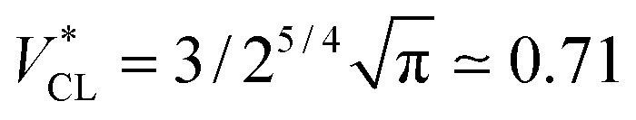 .10 Note that thermal fluctuations give an additional curvature energy as Ucv ≃ UCL + (Nmb − 1)kBT/2 in the simulations because each bending mode is excited with kBT/2. It was predicted that the ring vesicles are non-axisymmetric at V* > V*CL but axisymmetric at V* ≤ V*CL.11 Our simulation results confirm their prediction for the ring. Although the circular shapes at V* ≤ V*CL are not exactly axisymmetric, its deviation is small and can be understood as thermal fluctuations around the circular toroids. The area difference Δa of the revolution expressed in eqn (4) is shown in the right black dashed line in Fig. 1(b). Our simulation results agree well with this estimation.
The axisymmetric double-necked stomatocyte (called a sickle-shaped toroid) is predicted as the global-minimum state at low V* in the previous study.11 In our simulations, two necks (or pores in the top view) of the stomatocyte are not typically along the center axis [see the left snapshot in Fig. 1(a)]. Experimentally observed double-necked stomatocytes are also off-center [see Fig. 2(a)]. The narrow neck shape is nearly catenoid, and its mean curvature is negligibly small. The energy difference between the axisymmetric and non-axisymmetric stomatocytes is small unless two necks are close to each other. The entropy of this diffusion is estimated as Spore ≃ kBln(A/2dpore2), where dpore is the diameter of the pores and A/2 is the average area of inner and outer spherical components of stomatocytes. We obtain Spore ≃ 5kB from A = 820σ2 and dsto ≃ 2σ in our simulation. This is not a large value but it seems to be sufficient to overcome the energy difference. Thus, two necks can diffuse on the surface of the vesicle by thermal fluctuations. Vesicle deformation coupled with neck diffusion is observed. The membrane between two necks typically has large curvature [see Fig. 1(a) and 2(a)]. The entropy of these shape fluctuations and pore shape fluctuations30 may also increase the stability of non-axisymmetric shapes of the stomatocyte. The left black dashed line in Fig. 1(b) shows the values of Δa of stomatocytes modeled using two spheres. The shape deformation caused by thermal fluctuations slightly shifts Δa to larger values.
 | ||
| Fig. 2 Microscopy images of genus-1 liposomes. (a) Double-necked stomatocyte. (b) Open stomatocyte. (c) Ellipsoidal toroid. (d) Discocyte with a tubular handle and arm. Scale bar: 10 μm. | ||
The pore in the discocyte is also off-center. We discuss this in detail in the next subsection. In Jülicher's phase diagrams,13 the equilibrium shapes are axisymmetric in a large region including the stomatocyte and ring (see Fig. 3). We will show non-axisymmetric equilibrium shapes in this region for low V*.
 | ||
| Fig. 3 Shape transition lines of the genus-1 vesicles with the ADE and BC models. The red and blue solid lines represent the shape transitions in ADE and BC models, respectively. Cdisk and D represent the continuous and discrete transitions between the open stomatocyte and disk and between the elongated disk and circular toroid, respectively. The black and gray lines are ADE and BC boundaries extracted from Jülicher's phase diagrams in ref. 13, respectively. The dashed lines represent phase boundaries between axisymmetric and non-axisymmetric shapes (Cnsym). The filled circle represents the Clifford torus (CL). The magenta line represents the free-energy minimum states of the ring [the same as in Fig. 1(b)]. | ||
ln(Pcv(Δa)) + C. The constant C is unknown. Thus, we cannot obtain the absolute values of F but can compare its relative values. In Fig. 4–6(b), we shift F to be close to 〈U0〉 in order to make the comparison of two curves easier. The difference between Δa dependences of F and 〈U0〉 is caused by the entropy of membrane fluctuations.
 | ||
| Fig. 4 Dependence of shape on Δa (BC) or Δa0 (ADE) for genus-1 vesicles at V* = 0.6. (a) Snapshots at Δa = 0.6, 0.9, 1.1, 1.2, and 1.35. The side views of half-cut snapshots are also shown at Δa = 1.1 and 1.2. (b) Free-energy profile F and mean potential energy 〈U0〉 for the BC model. (c) Mean asphericity 〈αsp〉 for the BC and ADE models with k*ade = 1. (d) Mean area difference 〈Δa〉. The solid lines represent the ADE models with k*ade = 0.25, 0.5, 1, and 2. The dashed line represents the BC model (〈Δa〉 = Δa). The error bars are smaller than the line thickness. | ||
 | ||
| Fig. 5 Dependence of shape on Δa (BC) or Δa0 (ADE) for genus-1 vesicles at V* = 0.5. (a) Snapshots at Δa = 1.25, 1.4, and 1.55. The side views of half-cut snapshots are also shown at Δa = 1.25 and 1.4. (b) Free-energy profile F and mean potential energy 〈U0〉 for the BC model. (c) Mean asphericity 〈αsp〉 for the BC and ADE models with k*ade = 1. (d) Mean area difference 〈Δa〉. The data are presented in the same form as in Fig. 4. | ||
 | ||
| Fig. 6 Dependence of shape on Δa (BC) or Δa0 (ADE) for genus-1 vesicles at V* = 0.4. (a) Snapshots at Δa = 1.3, 1.5, 1.7, and 1.9. The side view of the half-cut snapshot at Δa = 1.3 is also shown. (b) Free-energy profile F and mean potential energy 〈U0〉 for the BC model. (c) Mean asphericity 〈αsp〉 for the BC and ADE models with k*ade = 1. (d) Mean area difference 〈Δa〉. The data are presented in the same form as in Fig. 4. | ||
To quantify the vesicle shapes, a shape parameter called asphericity, αsp, is calculated. It is defined as31
 | (5) |
For V* = 0.6 with increasing Δa, a neck of the stomatocyte opens, and subsequently the stomatocyte transforms into a discocyte (see Fig. 4). As Δa increases further, the pore in the discocyte becomes larger, and ultimately a circular toroid is formed. As Δa increases even further, the toroid elongates in one direction. This elongated shape is also observed in our experiment [compare Fig. 2(c) and 4(a)]. These transformations are continuous in both BC and ADE models with k*ade ≥ 1. When the vesicle transforms from the discocyte to the open stomatocyte, mirror symmetry breaks, and the slopes of F(Δa) and the other quantities are changed. This is a second-order type of the transition, but the transition point is rounded by the finite energy increase. Since the curvature energy is independent of the vesicle size, the transition is not sharp even at Nmb = ∞. The area differences Δa and Δa0 at this transition point are estimated from the second derivative of αsp curves in Fig. 4(c). They agree with Jülicher's results for both ADE and BC models (see the curves denoted by Cdisk in Fig. 3). The pore of the discocyte appears near the center of the disk. As the vesicle is annealed to T = 0, the pore moves to the center. Thus, it is considered that the stable shape is the axisymmetric discocyte predicted in ref. 13 and that the discocyte is slightly deformed by thermal fluctuations. The discocyte does not have a minimum in the free-energy profile in Fig. 4(b), and no clear transitions are observed between the discocyte and circular toroid. The neck in the open stomatocyte can also be off-center. Such a non-axisymmetric open stomatocyte is experimentally observed, as shown in Fig. 2(b).
At V* = 0.5, the vesicle transforms from a stomatocyte to a circular toroid via a discocyte [see Fig. 1(a) and 5]. The difference from V* = 0.6 is that the discocyte is at a minimum of F(Δa) and non-axisymmetric elongated discocytes appear between two energy minima of the discocyte and ring. In the stable discocyte [the middle snapshot in Fig. 1(a)], the pore is off-center and stays on the edge of the dimple. As the vesicle is annealed to T = 0, the pore remains on the edge. We also confirmed the formation of these non-axisymmetric discocytes at Nmb = 4000. Michalet and Bensimon experimentally observed this off-center discocyte.18 They reported that it is an energy minimum state by using the energy minimization, but they did not clarify whether it is the global- or local-minimum state.18 Our simulation revealed that the off-center discocyte is the global-minimum state in both BC and ADE models. In the axisymmmetric discocyte, the pore opens in the almost flat membranes at the middle of the dimples. As the pore approaches the edge of the dimples, the curvature of the edge is partially reduced. Similar pore formations on the edge of the highly curved structures are obtained in membrane-fusion intermediates. The fusion pore opens at the edge of a hemifusion diaphragm32,33 and at the side of a stalk neck connecting two bilayer membranes.34,35
As Δa increases at V* = 0.5, the pore in the discocyte is expanded at this off-center position, and the vesicle becomes an elliptic discocyte [see the left snapshot in Fig. 5(a) and the peak at Δa = 1.25 in Fig. 5(c)]. In the BC model, the vesicle then becomes a circular toroid via an elongated circular toroid [see the middle snapshot in Fig. 5(a)]. In contrast, in the ADE model with k*ade = 1, the vesicle exhibits a discrete transition from an elliptic discocyte to a circular toroid at Δa0 = 1.36. This transition point agrees with the prediction in ref. 13 (see Fig. 3), despite the fact that only axisymmetric shapes are considered in ref. 13. This good agreement might be due to the small energy difference between the axisymmetric discocyte and elliptic discocyte.
At V* = 0.4, the vesicle forms pronounced non-axisymmetric shapes between the off-center circular discocyte and circular toroid (see Fig. 6). The pore is not in the dimples of the discocyte but outside of the discocyte, which is similar to a handle, as shown in the right snapshot in Fig. 6(a). We also observed this shape experimentally (see the left images in Fig. 7). Such a handled discocyte has not been reported previously. With decreasing V*, the elliptic discocyte becomes more elongated, and subsequently the large flat parts form dimples. As Δa increases, the pore becomes larger and the discoidal part becomes narrower. When Δa is further increased in the BC model, the vesicles form a tubular arm similar to the grip of a racket [see Fig. 6(a)] and subsequently become a circular toroid. In the ADE model, the racket-shaped vesicle is skipped in the phase diagram, and a discrete transition from the elongated handled discocyte of a = 1.25 to the circular toroid of Δa = 1.81 occurs at Δa0 = 1.77 [see Fig. 6(c)]. The transition point is slightly shifted from the previous prediction for the transition from the axisymmetric disk and ring13 (see Fig. 3), because of a large deviation of the discocyte from the axisymmetric shape. The racket-shaped vesicle exists as a local-minimum state at larger values of Δa0 [see Fig. 8(b)]. In the experiment, a handled discocyte with a tubular arm is observed [see Fig. 2(d)]. A similar shape is obtained as a local energy-minimum state in the ADE model [see Fig. 8(a)]. A circular toroid connecting two tubular arms is also obtained (data not shown). At low V*, tubular arms often remain once they are formed such that several local-minimum states appear.
 | ||
| Fig. 7 Time-sequential microscopy images of genus-1 liposomes. (a) Transformation from a circular toroid to a racket shape via a handled discocyte. From left to right: t = 0, 160, 180, 188, and 192 s. (b) Transformation from a handled discocyte to stomatocyte via a discocyte with a small pore and open stomatocyte. From left to right: t = 0, 62, 80, 91, and 131 s. Scale bar: 10 μm. | ||
 | ||
| Fig. 8 Snapshots of genus-1 vesicles. (a) (V*, Δa0) = (0.3, 2.2). (b) (V*, Δa0) = (0.4, 1.9). (c) (V*, Δa0) = (0.5, 2.2). (d) (V*, Δa0) = (0.5, 2.2). | ||
Fig. 7 shows time-sequential microscopy images of shape transformations of genus-1 vesicles. These transformations from a handled discocyte to a racket shape and stomatocyte are well explained by gradual changes of Δa0 at V* = 0.3: from Δa0 = 2.2 to 2.6 [Fig. 7(a)] and from Δa0 = 2.3 to 0.6 [Fig. 7(b)], respectively. Movies of corresponding simulations are provided in the ESI (Movies 1 and 2†).
The entropy of the shape fluctuations slightly modifies the phase behavior. The area difference Δa at the minimum free energy is smaller than that at the minimum of the mean potential energy 〈U0〉 by 0.01 at V* = 0.5. The entropy of the shape fluctuations is large for the elongated discocyte because the difference of the curves 〈U0〉 and F are large at Δa ≃ 1.4 and 1.75 at V* = 0.5 and 0.4, respectively. The fluctuations of asphericity αsp are also large in these regions, and αsp exhibits broad distributions, as shown in Fig. 9.
 | ||
| Fig. 9 Probability distribution of asphericity αsp for genus-1 vesicles in the BC model at V* = 0.4. | ||
We have shown the discrete transition between an elongated discocyte and a circular toroid at V* = 0.5 and 0.4 for the ADE model with k*ade = 1. The transformation between a stomatocyte and a discocyte becomes a discrete transition at lower values of k*ade [see Fig. 4(d) and 5(d)]. With decreasing V*, a lower value of k*ade is needed to obtain the discrete transition. Thus, the values of k*ade may be estimated by systematically observing the transformation dynamics under changes in Δa0 or V*.
As Δa increases further from the circular toroid, the toroid deforms into an ellipsoid, triangle, and pentagon at V* = 0.6, 0.5, and 0.4, respectively. Thus, a higher undulation mode becomes unstable and grows at lower values of V*. When the vesicle is approximated as the circular revolution expressed in eqn (4), the length ratio of two circumferences are r1/r2 = 1.99, 2.86, and 4.48 at V* = 0.6, 0.5, and 0.4, respectively. Therefore, the unstabilized mode is determined by the wavelength of 2πr2. When r1/r2 → ∞, the toroid is approximated as a cylinder of radius r2. It is known that for cylindrical membranes of spontaneous curvature C0 the undulation mode of wavelength 2πr2 becomes unstable at C0r2 = 1.36 Our simulation results show that this relationship holds for finite values of r1/r2.
 | ||
| Fig. 10 Shape transformations of a genus-1 vesicle at V* = 0.55. (a) Time-sequential microscopy images of liposomes. From left to right: t = 0, 45, 95, 97, and 144 s. Scale bar: 10 μm. (b) Sequential snapshots of the triangulated-membrane simulation. Intrinsic area difference Δa0 is gradually increased with dΔa0/dt = 1 × 10⁻⁸, where t represents MC steps. From left to right: Δa0 = 1.73, 1.8, 1.87, 1.97, and 2.35. | ||
Since the budded compartments are divided by small necks, large free-energy barriers can exist between meta-stable and stable states. Thus, it is difficult to identify the most stable state. The snapshots in Fig. 8(c) and (d) show two free-energy-minimum states at (V*, Δa0) = (0.5, 2.2). The triangular and straight shapes are typically obtained as Δa0 increases and as V* decreases, respectively. These two shapes have almost identical potential energy with 〈U〉/κ = 120. As Δa0 gradually decreases from Δa0 = 2.2, the straight shape is retained better than the triangular budded shape at lower values of Δa0. A bud connected by two necks appears to be more robust than the one connected by a single neck. To calculate the free energies using a generalized ensemble method, order parameters to connect these budded states and the circular toroid are required. However, typical shape parameters such as αsp are not suitable, since the budding occurs in local regions of the vesicle.
3.2 Genus-2 toroidal vesicles
The genus-2 vesicles form closed and open stomatocytes, discocytes, and budded shapes (see Fig. 11 and 12). These shapes are similar to those of genus-1 vesicles described in the previous section. A significant difference is that no axisymmetric shapes exist for g = 2. Two pores cannot align at the center of the discocyte. | ||
| Fig. 11 (a) Microscopy images of liposomes of (i–iii) g = 2 and (iv) g = 5. Scale bar: 10 μm. (b) Snapshots for the toroidal vesicle of g = 2. (i) (V*, Δa0) = (0.5, 0.8). (ii) (V*, Δa0) = (0.5, 1). (iii) (V*, Δa0) = (0.5, 1.5). (iv) (V*, Δa0) = (0.5, 1.8). (v) (V*, Δa0) = (0.35, 2.7). | ||
 | ||
| Fig. 12 Shape transformations of a genus-2 vesicle at V* = 0.25. (a) Time-sequential microscopy images of liposomes. From left to right: t = 0, 84, 197, and 244 s. Scale bar: 10 μm. (b) Sequential snapshots of the triangulated-membrane simulation. Intrinsic area difference Δa0 is gradually decreased with dΔa0/dt = 2 × 10⁻⁸. From left to right: Δa0 = 4, 3.46, 2.6, and 2. | ||
A discocyte with two handles is observed experimentally. The time-sequential shape transformation from a budded toroid to a handled discocyte is well reproduced by our simulation [compare Fig. 12(a) and (b)].
The size of two pores in the vesicles can be different. An extreme example is shown in Fig. 11(a,iii) and (b,v). The ends of a tubular vesicle are connected by two necks. This shape is metastable and obtained in the region slightly below the budding transition. At g > 2, more complicated shapes are expected. Fig. 11(a,iv) shows an example of genus-5 liposomes.
4 Conclusions
Various morphologies of the genus-1 and 2 toroidal vesicles are clarified numerically and experimentally. For g = 1, new stable non-axisymmetric shapes are revealed from the free-energy profile calculation. As Δa increases at V* = 0.5, a circular discocyte with an off-center pore transforms into an elliptic discocyte and then into a circular toroid. At V* = 0.4, between the circular discocyte and circular toroid, the discocyte with a handle and racket shape are formed. The discrete transition occurs between the elliptic discocyte and circular toroid in the ADE model. The handled discocytes are also observed for g = 2. On increasing Δa further, the formation of polygonal toroidal vesicles and subsequential budding are also found. The number of polygon edges are increased with decreasing V* and are understood by the bending instability. Our simulation results agree with our experimental observation very well. The following shapes are experimentally observed for the fist time: stomatocytes and racket-shaped vesicle for genus-1 and handled discocytes for genus-1 and 2.As the genus of vesicles increases, the regions of non-axisymmetric shapes are expanded in the phase diagram. For g = 1, the non-axisymmetric discocytes are stable in the region where the axisymmetric discocytes are formed for g = 0. For g = 2, all of the obtained shapes are non-axisymmetric. Although the phase diagram of the genus-2 vesicles is investigated on the basis of symmetry analyses in ref. 14 and 15, thermal fluctuations are neglected. A hexagonal array of pores is observed in polymersomes.37 Shape transformations of the vesicles of genus 2 and higher under thermal fluctuations are an interesting problem for further studies.
Acknowledgements
The authors would like to thank G. Gompper for informative discussions. This work was partially supported by a Grant-in-Aid for Scientific Research on Innovative Areas “Fluctuation & Structure” (no. 25103010) from the Ministry of Education, Culture, Sports, Science, and Technology of Japan. The numerical calculations were partly carried out on an SGI Altix ICE 8400EX at ISSP Supercomputer Center, University of Tokyo.References
- Structure and Dynamics of Membranes, ed. R. Lipowsky and E. Sackmann, Elsevier Science, Amsterdam, 1995 Search PubMed.
- R. Lipowsky, Statistical mechanics of biocomplexity, Springer, Berlin, 1999, vol. 527, pp. 1–23 Search PubMed.
- U. Seifert, Adv. Phys., 1997, 46, 13–137 CrossRef CAS.
- S. Svetina and B. Žekš, Anat. Rec., 2002, 268, 215–225 CrossRef CAS PubMed.
- S. Svetina and B. Žekš, Euro. Biophys. J., 1989, 17, 101–111 CrossRef CAS.
- N. Khalifat, N. Puff, S. Bonneau, J.-B. Fournier and M. I. Angelova, Biophys. J., 2008, 95, 4924–4933 CrossRef CAS PubMed.
- H. Noguchi, J. Phys. Soc. Jpn., 2009, 78, 041007 CrossRef.
- A. Sakashita, N. Urakami, P. Ziherl and M. Imai, Soft Matter, 2012, 8, 8569–8581 RSC.
- A. Sakashita, M. Imai and H. Noguchi, Phys. Rev. E: Stat., Nonlinear, Soft Matter Phys., 2014, 89, 040701(R) CrossRef.
- Z. C. Ou-Yang, Phys. Rev. A, 1990, 41, 4517–4520 CrossRef CAS.
- U. Seifert, Phys. Rev. Lett., 1991, 66, 2404–2407 CrossRef.
- B. Fourcade, M. Mutz and D. Bensimon, Phys. Rev. Lett., 1992, 68, 2551–2554 CrossRef CAS.
- F. Jülicher, U. Seifert and R. Lipowsky, J. Phys. II, 1993, 3, 1681–1705 CrossRef.
- F. Jülicher, U. Seifert and R. Lipowsky, Phys. Rev. Lett., 1993, 71, 452–455 CrossRef.
- F. Jülicher, J. Phys. II, 1996, 6, 1797–1824 CrossRef.
- X. Michalet, D. Bensimon and B. Fourcade, Phys. Rev. Lett., 1994, 72, 168–171 CrossRef CAS.
- X. Michalet and D. Bensimon, Science, 1995, 269, 666–668 CAS.
- X. Michalet and D. Bensimon, J. Phys. II, 1995, 5, 263–287 CrossRef CAS.
- X. Michalet, Phys. Rev. E: Stat., Nonlinear, Soft Matter Phys., 2007, 76, 02914 CrossRef.
- A. Yamamoto and M. Ichikawa, Phys. Rev. E: Stat., Nonlinear, Soft Matter Phys., 2012, 86, 061905 CrossRef.
- G. Gompper and D. M. Kroll, J. Phys.: Condens. Matter, 1997, 9, 8795–8834 CrossRef CAS.
- G. Gompper and D. M. Kroll, Statistical Mechanics of Membranes and Surfaces, World Scientific, Singapore, 2nd edn, 2004 Search PubMed.
- P. B. Canham, J. Theor. Biol., 1970, 26, 61–81 CrossRef CAS.
- W. Helfrich, Z. Naturforsch., 1973, 28c, 693–703 Search PubMed.
- C. Itzykson, Proceedings of the GIFT Seminar, Jaca 85, Singapore, 1986 Search PubMed.
- H. Noguchi and G. Gompper, Phys. Rev. E: Stat., Nonlinear, Soft Matter Phys., 2005, 72, 011901 CrossRef.
- Y. Okamoto, J. Mol. Graphics Modell., 2004, 22, 425–439 CrossRef CAS PubMed.
- B. A. Berg, H. Noguchi and Y. Okamoto, Phys. Rev. E: Stat., Nonlinear, Soft Matter Phys., 2003, 68, 036126 CrossRef.
- A. M. Ferrenberg and R. H. Swendsen, Phys. Rev. Lett., 1988, 61, 2635–2638 CrossRef CAS.
- O. Farago and C. D. Santangelo, J. Chem. Phys., 2005, 122, 044901 CrossRef PubMed.
- J. Rudnick and G. Gaspari, J. Phys. A: Math. Gen., 1986, 19, L191–L193 CrossRef.
- H. Noguchi, J. Chem. Phys., 2002, 117, 8130–8137 CrossRef CAS PubMed.
- H. Noguchi, Soft Matter, 2012, 8, 3146–3153 RSC.
- H. Noguchi and M. Takasu, J. Chem. Phys., 2001, 115, 9547–9551 CrossRef CAS PubMed.
- M. Müller and M. Schick, Curr. Top. Membr., 2011, 68, 295–323 CrossRef PubMed.
- Z. C. Ou-Yang and W. Helfrich, Phys. Rev. A, 1989, 39, 5280–5288 CrossRef CAS.
- C. K. Haluska, W. T. Góźdź, H.-G. Döbereiner, S. Förster and G. Gompper, Phys. Rev. Lett., 2002, 89, 238302 CrossRef.
Footnote |
| † Electronic supplementary information (ESI) available. See E-mail: DOI: 10.1039/c4sm01890g |
| This journal is © The Royal Society of Chemistry 2015 |