
 Open Access Article
 This Open Access Article is licensed under a
 Creative Commons Attribution 3.0 Unported Licence
Fabrication of a novel TiO2/S composite cathode for high performance lithium–sulfur batteries
Keyu
Xie
a,
Yunzhao
Han
a,
Wenfei
Wei
a,
Haoran
Yu
a,
Cunbao
Zhang
a,
Jian-Gan
Wang
a,
Wei
Lu
b and
Bingqing
Wei
*ac
aState Key Laboratory of Solidification Processing and Center for Nano Energy Materials, Northwest Polytechnical University, Xi'an 710072, China
bDepartment of Applied Physics and Materials Research Center, The Hong Kong Polytechnic University, Hong Kong, China
cDepartment of Mechanical Engineering, University of Delaware, Newark, DE19716, USA. E-mail: weib@udel.edu; Fax: +1-302-831-3619; Tel: +1-302-831-6438
First published on 8th September 2015
Abstract
Sulfur is an attractive cathode material with a high specific capacity of 1675 mA h g−1, but its rapid capacity decay due to polysulfide dissociation presents a significant technical challenge. Here, we present the fabrication of a TiO2/S composite cathode by encapsulating elemental sulfur into TiO2 nanotube hosts for high performance lithium–sulfur batteries. A high capacity of 913 mA h g−1 has been achieved at a rate of 0.2C in the initial cycle for the TiO2/S composite cathode with a sulfur content of 65 wt% and the reversible capacity remains as high as 851 mA h g−1 after 100 cycles. The improvements of electrochemical performances were attributed to the good dispersion of sulfur in the TiO2 nanotubes and the excellent adsorbing effect on polysulfides of TiO2.
Introduction
The emerging fields of electric vehicles and hybrid electric vehicles demand significant improvement of rechargeable battery technologies to achieve higher energy densities.1–3 Unfortunately, the energy density and cycle life of the presently available lithium-ion battery (LIB) remain insufficient for many of the aforementioned applications.4,5 Lithium–sulfur (Li–S) batteries have been reported as one of the highly promising rechargeable lithium batteries due to the high theoretical capacity (1675 mA h g−1), high energy density (2600 W h kg−1), low cost, and natural abundance of sulfur.4–6 Although this battery system has been attracting attention for more than two decades, it has not been commercialized on a large scale due to several unsolved problems. It is known that sulfur particles suffer from the problems of: (a) poor electronic conductivity, (b) dissolution of intermediate polysulfides (creating an internal “shuttle effect”), and (c) large volumetric expansion (∼80%) upon lithiation, which result in a rapid capacity decay and low coulombic efficiency.7–11 Therefore, enhancing the ionic/electronic conductivity and trapping the polysulfides to prevent the dissolution are critical to develop high energy density and long-lasting Li–S batteries.To tackle the issues, sulfur is always combined with porous substrates through proper structural designs (surface coating and/or sulfur loading) to effectively confine sulfur on the cathode side and limit dissolution of polysulfides in electrolyte. These substrates include mesoporous carbon,12,13 microporous carbon,14 graphene,15,16 porous carbon fibers,13,17,18 polymer additives,19,20 and metal oxides21–23 that limit the dissolution of polysulfides through both physical and chemical interactions.
Recently, the advance in design and synthesis of the suitable porous substrates with a strong ability to chemically absorb sulfur species is particularly attractive.24 For example, Wang et al. demonstrated noticeable enhancements in the cycling stability caused by nitrogen doping promoted chemical adsorption in a series of nitrogen-doped nanocarbon based cathodes.24–26 Meanwhile, metal oxides, such as TiO2,7 Ti4O7,21 and MnO2,27 were also proved to be an efficient intermediary to form the strong chemical bonding between polysulfides and metal oxides. As a result, these semiconducting or metallic oxides have been introduced into the cathode as high-performance sulfur host materials.
Hence, in this work, we design and fabricate a novel structured cathode for Li–S batteries, with sulfur encapsulated in a TiO2 nanotube host, as illustrated in Fig. 1. In this cathode, TiO2 nanotubes were prepared by an improved hydrothermal process and a subsequent thermal treatment,28,29 and the TiO2/S composites were prepared by a typical melt-diffusion strategy. Electrochemical measurements indicate that the TiO2/S composite exhibits excellent cycling stability, which is mainly attributed to the significant roles that the TiO2 nanotubes played during the electrochemistry reactions. The TiO2 nanotubes can prevent the polysulfides from dissolving in electrolyte and minimize the “shuttle effect”; at the same time, can promote the interaction between TiO2 and S, which was believed to be an electrostatic attraction (S–Ti–O) that improved the surface adsorption of polysulfides onto TiO2 surfaces.13,30
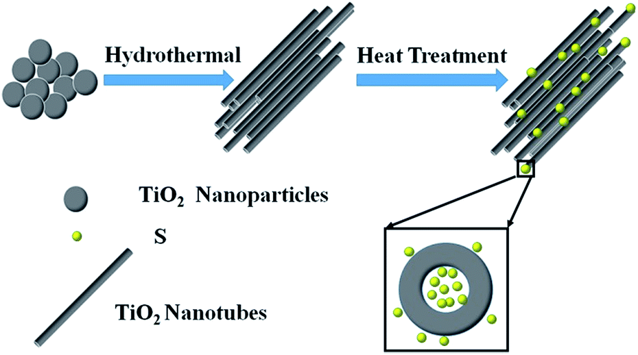 | ||
| Fig. 1 Schematic illustration of the assembled TiO2/S composites for improving cathode performance. | ||
Experimental
Fabrication of TiO2 nanotubes
The TiO2 nanotubes were synthesized by a hydrothermal method.29 In a typical process, 0.4 g of TiO2 powder was dispersed into 60 mL of NaOH solution (10 M) with continuous stirring for 10 min. After that, the obtained solution was transferred into 100 mL Teflon-lined stainless-steel autoclave, which was put inside a silicon oil bath on a hot plate and the reaction temperature was set at 150 °C for 24 h while the stirring rate is 800 rpm. After reaction, the autoclave was taken out from the oil bath and cooled to room temperature. The product, sodium titanate, collected by vacuum drawing and filtering, was washed with deionized water for several times to reach a pH value of 9. After that, the sodium titanate was subjected to a hydrogen ion exchange process in a diluted HNO3 solution (0.1 M) for three times. Finally, the suspension was filtered again, washed with deionized water for several times until a pH value of 7 was reached, generating the hydrogen titanate nanotube. Then the hydrogen titanate nanotube was heated at 450 °C for 2 h in a muffle furnace and the TiO2 nanotubes was obtained after cooling down to room temperature.Preparation of TiO2/S composites
To prepare TiO2/S composites, elemental sulfur was mixed with TiO2 nanotubes while the mass ratio could be controlled. In a typical experiment, the TiO2 nanotubes and elemental sulfur were mixed with a mass ratio of 1![[thin space (1/6-em)]](https://www.rsc.org/images/entities/char_2009.gif) :1.05 (1:2.05). Then the mixtures were heated at 155 °C for 10 h in a sealed vessel filled with argon gas. After cooling down, the TiO2/S composites with a mass ratio of 1:1 (1:2) were obtained.
:1.05 (1:2.05). Then the mixtures were heated at 155 °C for 10 h in a sealed vessel filled with argon gas. After cooling down, the TiO2/S composites with a mass ratio of 1:1 (1:2) were obtained.
Characterization
X-ray diffraction (XRD) patterns were measured on an X'Pert PRO MPD. Cu K line was used as a radiation source with λ = 0.15418 nm. Scanning electron microscopy (SEM) and transmission electron microscopy (TEM) measurements were carried out with Quanta 600 FEG and FEI Tecnai F30G2, respectively. The N2 adsorption–desorption were determined by Brunauer–Emmett–Teller (BET) measurements using an ASAP-2020 surface area analyzer. The sulfur content of TiO2/S was determined by a thermal gravimetric analysis (TGA/SDTA851, Switzerland) from room temperature to 500 °C at a ramping rate of 10 °C min−1 in air flow.Electrochemical measurements
The TiO2/S electrode was prepared by mixing the TiO2/S composites, acetylene black and polyvinylidene fluoride (PVDF) at a weight ratio of 70:20:10 in N-methyl-2-pyrrolidone (NMP) to form homogeneous slurry under magnetic stirring. The slurry was then plastered onto aluminum foil using a doctor blade, and dried at 60 °C for 24 h in a vacuum oven. The areal mass loading of sulfur is ∼1.1 mg cm−2. The electrochemical measurements were performed by two-electrode coin cells (CR 2016) with Li foil as both counter electrode and reference electrode at ambient temperature and polypropylene (PP) film as the separator. The electrolyte was 1 M lithium bis(trifluoromethanesulfone)imide (LiTFSI) and 0.1 M LiNO3 in a mixed solvent of 1,3-dioxolane (DOL) and 1,2-dimethoxyethane (DME) with a volume ratio of 1:1. The coin cells were galvanostatically charged–discharged at different current densities between 1.8 and 3.0 V (vs. Li/Li+) using a CT2001A cell test instrument (LAND Electronic Co, BT2013A, China). The cyclic voltammetry (CV) test and electrochemical impendance spectroscopy (EIS) measurement were performed on electrochemical workstation (Solartron analytical 1400) with a voltage range of 1.8–3.0 V (vs. Li/Li+) at a scanning rate of 0.1 mV s−1 and a frequency window from 0.01 Hz to 100 kHz while the disturbance amplitude was 5 mV, respectively.
Results and discussion
Characterization of prepared TiO2 nanotubes and TiO2/S composites
Fig. 2 shows the XRD patterns of TiO2 nanotubes, TiO2/S composites, element sulfur, and the mixture of TiO2 nanotubes and elemental sulfur. All of the identified peaks can be perfectly indexed to anatase TiO2 (JCPDS card no. 21-1272). In the XRD pattern of the mixture of TiO2 nanotubes and elemental sulfur, the intense diffraction peaks of crystallized sulfur and anatase TiO2 could clearly be observed. In contrast, the diffraction peaks of sulfur become very weak after being encapsulated into the TiO2 nanotube hosts, indicating good dispersion of sulfur within the TiO2 nanotube host, which is similar to that of carbon/sulfur composites in previous reports.31 However, because of the high loading of sulfur, some sulfur coating on the surface might nucleate to form sulfur particles.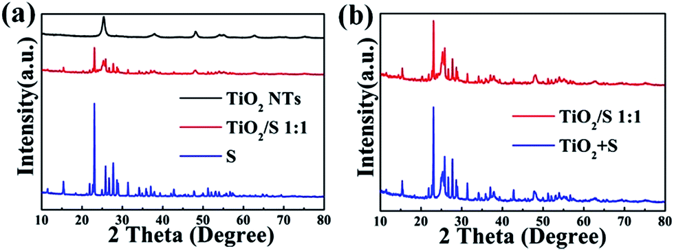 | ||
| Fig. 2 XRD patterns of (a) TiO2 nanotubes, TiO2/S composites, elemental sulfur and (b) TiO2/S composites, the mixture of TiO2 nanotubes and elemental sulfur. | ||
The SEM images of commercial TiO2 particles and TiO2 nanotubes are shown in Fig. 3a and b. It can be clearly identified that the typical diameter of the TiO2 particles is in range of 100–120 nm (Fig. 3a) while the average diameter of TiO2 nanotubes is about 80–100 nm (Fig. 3b). After elemental sulfur encapsulating, the morphology of the TiO2/S composites (Fig. 3c) becomes continuous and disorganized. To further determine the distribution of elemental sulfur in the TiO2/S composites, element mappings for the composites had been taken. Fig. 3d–f show the element mappings for sulfur, titanium and oxygen based on the area shown in Fig. 3c. The element mappings for sulfur and titanium display a very similar intensity distribution, further indicating that element sulfur are uniformly distributed in the TiO2/S composites. This result can also be verified from the following TEM image and corresponding element mapping (Fig. 4).
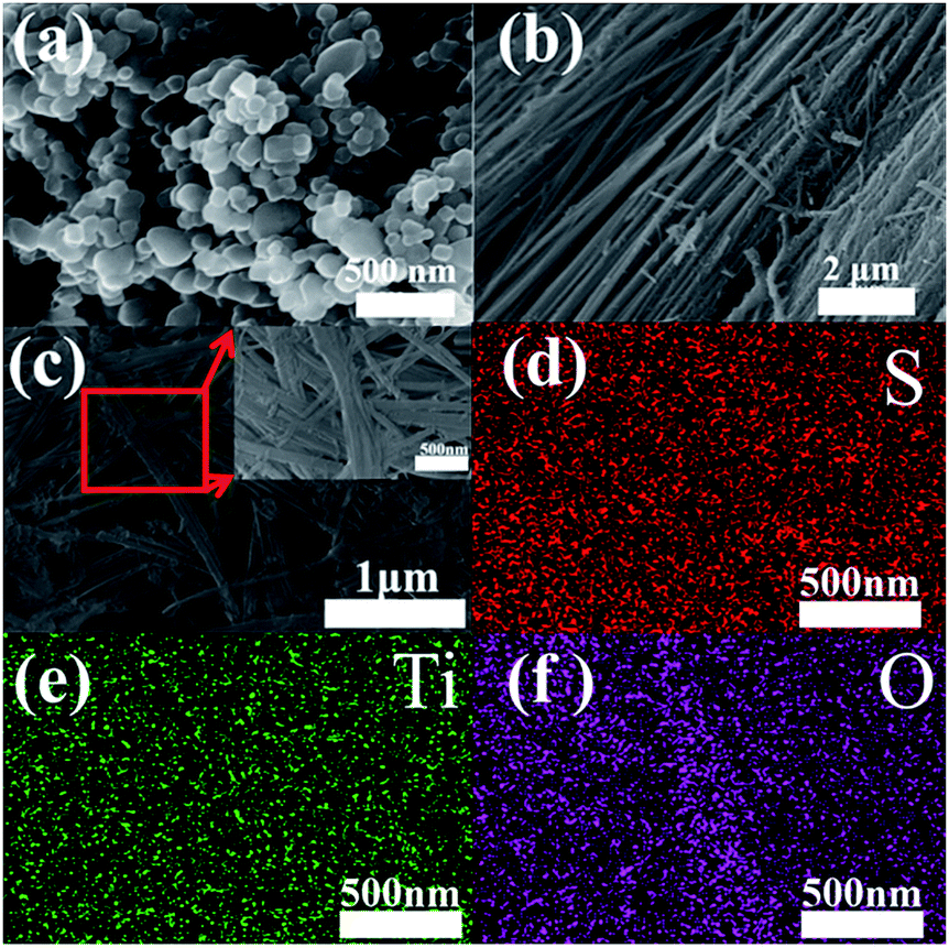 | ||
| Fig. 3 SEM images of (a) commercial TiO2 particles and (b) TiO2 nanotubes; (c) FESEM image of TiO2/S composites; inset: high resolution FESEM image of the TiO2/S composites, and the corresponding element mapping of (d) S, (e) Ti and (f) O. | ||
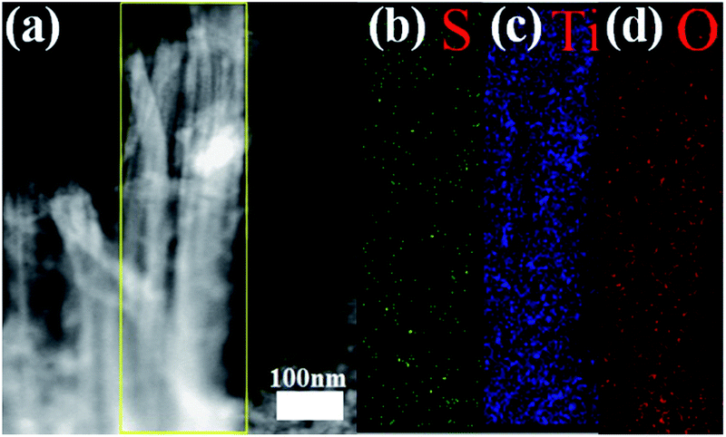 | ||
| Fig. 4 TEM image of (a) TiO2/S composites and the corresponding element mapping of (b) S, (c) Ti and (d) O. | ||
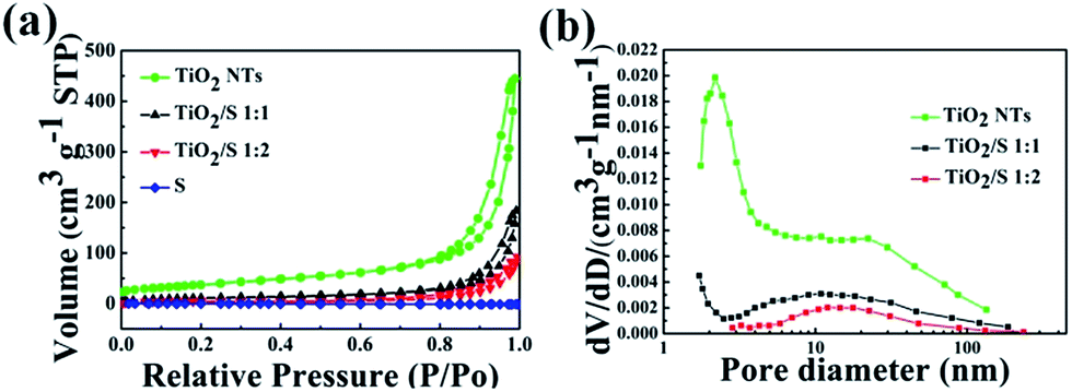
Nitrogen adsorption–desorption isotherms and pore size distribution curves of the prepared TiO2 derived from BET measurements are depicted in Fig. 5. The nanotube structure of TiO2 nanotube gives rise to a relatively high BET surface area of 134.85 m2 g−1 and a pore volume of 0.69 cm3 g−1. The nitrogen adsorption–desorption isotherms of the TiO2/S composites with a mass ratio of 1:1 and 1:2 were also shown in Fig. 5. It's clear that the adsorption volumes become lower. The BET surface area of TiO2/S composites (1:1 and 1:2) dramatically decreases to 40.70 m2 g−1 and 11.52 m2 g−1, respectively. In addition, with the increasing of the sulphur loading, the pore size distribution plot in Fig. 5b shows that there is a significant decrease of small mesopores from 2 to 4 nm, while the large mesopores are also slight reduced. The BET results indicate that the loaded sulfur in TiO2/S composites mainly occupies the mesopores of TiO2 nanotubes.
 | ||
| Fig. 5 (a) Nitrogen adsorption–desorption isotherms of TiO2 nanotubes, TiO2/S composites (1:1, 1:2), element sulfur and (b) corresponding pore-size-distribution. | ||
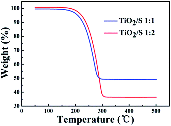
The thermal decomposition characteristic of the TiO2/S composites (the mass ratios of TiO2 nanotubes and S are 1:1 and 1:2) was investigated under an air atmosphere by means of TGA (Fig. 6). Both TGA curves of TiO2/S composites show one weight loss stage from around 200 to 300 °C, which corresponds to the evaporation of sublimed sulfur. The corresponding weight loss of TiO2/S composites is approximately up to 50 wt% and 65 wt%, respectively, which is consistent with the proportions of the added amount.
 | ||
| Fig. 6 TGA curves of TiO2/S composites. | ||
Electrochemical properties of the TiO2/S composites electrode
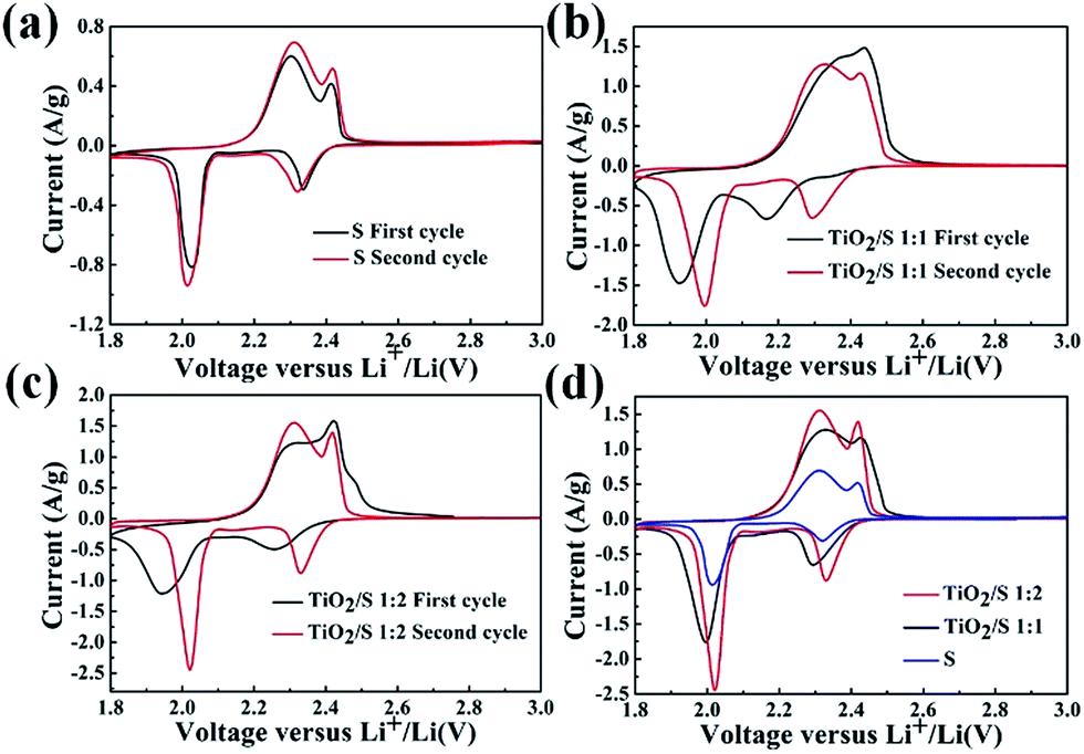
CV curves of pristine sulfur electrode and the TiO2/S composite cathodes (1:1, 1:2) at a scan rate of 0.1 mV s−1 are shown in Fig. 7. Fig. 7a shows a typical CV curve of pure sulfur electrode. The peak at 2.30 V associates with the conversion of elemental sulfur to soluble lithium polysulfide (Li2Sn, 4 ≤ n ≤ 8), and the peak at 2.05 V is related to the reduction of lithium polysulfides to insoluble Li2S2 and Li2S.32–34 In the anodic scan, two oxidation peaks are observed at the potentials of 2.36 V and 2.45 V, which correspond to the conversion of Li2S into high-order soluble polysulfides.35,36 Therefore, according to the CV curves, the “integration” reaction of elemental sulfur is the mainly electrochemical reaction process of the TiO2/S composites cathode, as denoted in equation below.| S8 + 16e− + 16Li+ ↔ 8Li2S |
 | ||
| Fig. 7 Typical CV curves at 0.1 mV s−1 of (a) element sulfur cathode and TiO2/S composites cathode (b) (1:1), (c) (1:2); CV curves of the second cycle of the three electrode mentioned above (d). | ||
When compared with the CV curve of the element sulfur cathode (Fig. 7a), obvious differences could be observed from the CV curves of TiO2/S composites (Fig. 7b and c). The curves of the initial cycle are quite different from that of pure sulfur electrode, which is possibly owing to the redistribution of sulfur in the cathode through the electrochemical reactions at first cycle.
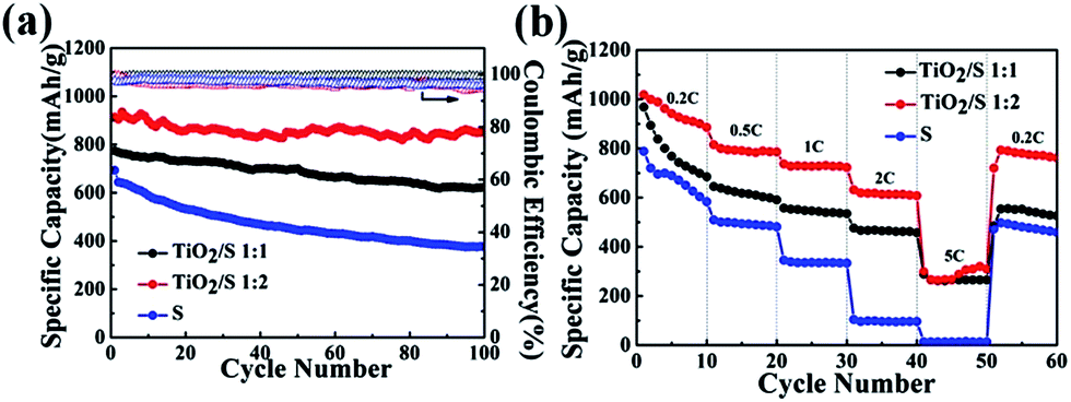
Cycling performance and rate capability of the TiO2/S composite cathodes (1:1, 1:2) and the element sulfur cathode are presented in Fig. 8. All capacity values in this study were calculated based on sulfur mass. Fig. 8a displays the cycling performance of the TiO2/S composite cathodes (1:1, 1:2) and the element sulfur cathode at a current rate of 0.2C (1C = 1675 mA g−1). The initial specific discharge capacity of the TiO2/S composite cathodes (1:1, 1:2) is about 795 mA h g−1 and 913 mA h g−1, respectively. After 100 cycles, the specific discharge capacity of the TiO2/S composite cathodes (1:1, 1:2) still retains 618 mA h g−1 and 851 mA h g−1, respectively. The excellent cyclic stability can be attributed to the good dispersion of sulfur in the TiO2 nanotube hosts. More importantly, chemical bond interaction between the titania and sulfur could permit fixed confinement of sulfur, which is critical to restrain the polysulfides and minimize the “shuttle effect”.13,21,30,37 Moreover, Fig. 8b obviously demonstrates that the rate performance of the TiO2/S composite cathodes (1:1, 1:2) is better than that of element sulfur cathode. The former can deliver a specific discharge capacity of 295 mA h g−1 and 302 mA h g−1, respectively, at a current rate of 5C, however, the element sulfur cathode could not deliver any discharge capacity at the same current density.
 | ||
| Fig. 8 (a) Cycling performances and (b) rate capability of the TiO2/S composites cathode and the element sulfur cathode. | ||
To further clarify the roles of TiO2 nanotubes played in the TiO2/S composite cathode, the EIS spectra of the TiO2/S composite cathodes (1:1, 1:2) and element sulfur cathode after 100 cycles were also measured. As shown in Fig. 9, all the EIS spectra were composed of a semicircle at high frequency and a nearly straight line at low frequency. The depressed semicircle in the high frequency region is assigned to the charge-transfer resistance (Rct), while the inclined line in the low frequency region represents the Warburg impedance (W), which is related to solid-state diffusion of lithium ions into the electrode material.38–41 It can be seen that the charge-transfer resistances of the two TiO2/S composites cathodes are much lower than that of element sulfur cathode. It could be attributed to the better conductivity of TiO2, which is a semiconductor, compared to sulfur, which is a insulator, and the nanotube-structure of the TiO2/S composite cathodes, which is helpful to absorb lithium polysulfides and reduce the negative impact of insulating precipitation on the cathode.32,42
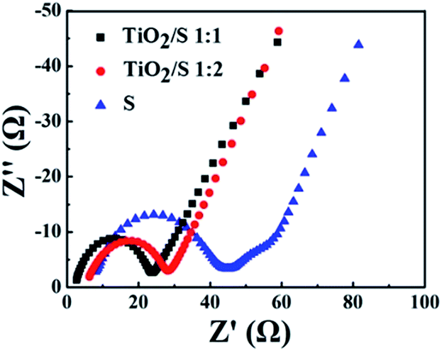 | ||
| Fig. 9 Impedance plots for the element sulfur cathode and the TiO2/S composite cathodes after 100 cycles. The insets show the corresponding EIS spectra at the high frequency domain. | ||
Conclusions
In summary, a novel TiO2/S cathode, consisted of TiO2 nanotubes and homogeneously distributed sulfur, has been successfully prepared by a typical melt-diffusion strategy. The TiO2/S composite shows high specific capacities and good cycling stabilities as well as rate capability, due to the crucial role TiO2 nanotube plays in the TiO2/S composite cathode during the electrochemical reaction. The specific capacity of TiO2/S composite reaches as high as 913 mA h g−1 in the initial cycle and remains above 93% after 100 cycles when the loaded weight of sulfur in the TiO2/S composite is 65 wt%. This result indicates that the TiO2 nanotube hosts could prevent the polysulfides from dissolving in the electrolyte and minimize the “shuttle effect” efficiently and successfully.Acknowledgements
The authors appreciate the financial support by the National Natural Science Foundation of China (51302219, 51472204 and 51402236), the Natural Science Foundation of Shaanxi Province (2015JM2045), the Specialized Research Fund for the Doctoral Program of Higher Education of China (No. 20136102120024), the Fundamental Research Funds for the Central Universities (3102014JCQ01019), and the Research Fund of the State Key Laboratory of Solidification Processing (NWPU), China (Grant No. 06-QP-2014).Notes and references
- T. M. Bandhauer, S. Garimella and T. F. Fuller, J. Electrochem. Soc., 2011, 158, R1–R25 CrossRef CAS PubMed.
- W. Qin, B. D. Fang, S. T. Lu, Z. D. Wang, Y. Chen, X. H. Wu and L. Han, RSC Adv., 2015, 5, 13153–13156 RSC.
- B. Ding, G. Xu, L. Shen, P. Nie, P. Hu, H. Dou and X. Zhang, J. Mater. Chem. A, 2013, 1, 14280 CAS.
- J. B. Goodenough and Y. Kim, Chem. Mater., 2010, 22, 587–603 CrossRef CAS.
- Z. Lin, Z. C. Liu, W. J. Fu, N. J. Dudney and C. D. Liang, Adv. Funct. Mater., 2013, 23, 1064–1069 CrossRef CAS PubMed.
- B. Ding, C. Z. Yuan, L. F. Shen, G. Y. Xu, P. Nie and X. G. Zhang, Chem.–Eur. J., 2013, 19, 1013–1019 CrossRef CAS PubMed.
- Z. W. Seh, W. Y. Li, J. J. Cha, G. Y. Zheng, Y. Yang, M. T. McDowell, P. C. Hsu and Y. Cui, Nat. Commun., 2013, 4, 1331 CrossRef PubMed.
- Z. W. Seh, S. H. Liu and M. Y. Han, Chem.–Asian J., 2012, 7, 2174–2184 CrossRef CAS PubMed.
- Z. W. Seh, H. T. Wang, N. Liu, G. Y. Zheng, W. Y. Li, H. B. Yao and Y. Cui, Chem. Sci., 2014, 5, 1396–1400 RSC.
- Z. W. Seh, J. H. Yu, W. Y. Li, P. C. Hsu, H. T. Wang, Y. M. Sun, H. B. Yao, Q. F. Zhang and Y. Cui, Nat. Commun., 2014, 5, 5017 CrossRef CAS PubMed.
- G. M. Zhou, S. F. Pei, L. Li, D. W. Wang, S. G. Wang, K. Huang, L. C. Yin, F. Li and H. M. Cheng, Adv. Mater., 2014, 26, 625–631 CrossRef CAS PubMed.
- X. L. Ji, K. T. Lee and L. F. Nazar, Nat. Mater., 2009, 8, 500–506 CrossRef CAS PubMed.
- J. Schuster, G. He, B. Mandlmeier, T. Yim, K. T. Lee, T. Bein and L. F. Nazar, Angew. Chem., Int. Ed., 2012, 51, 3591–3595 CrossRef CAS PubMed.
- D. W. Wang, Q. C. Zeng, G. M. Zhou, L. C. Yin, F. Li, H. M. Cheng, I. R. Gentle and G. Q. M. Lu, J. Mater. Chem. A, 2013, 1, 9382–9394 CAS.
- H. L. Wang, Y. Yang, Y. Y. Liang, J. T. Robinson, Y. G. Li, A. Jackson, Y. Cui and H. J. Dai, Nano Lett., 2011, 11, 2644–2647 CrossRef CAS PubMed.
- L. W. Ji, M. M. Rao, H. M. Zheng, L. Zhang, Y. C. Li, W. H. Duan, J. H. Guo, E. J. Cairns and Y. G. Zhang, J. Am. Chem. Soc., 2011, 133, 18522–18525 CrossRef CAS PubMed.
- X. L. Ji, S. Evers, R. Black and L. F. Nazar, Nat. Commun., 2011, 2, 325 CrossRef PubMed.
- J. C. Guo, Y. H. Xu and C. S. Wang, Nano Lett., 2011, 11, 4288–4294 CrossRef CAS PubMed.
- L. C. Yin, J. L. Wang, J. Yang and Y. N. Nuli, J. Mater. Chem., 2011, 21, 6807–6810 RSC.
- J. L. Wang, J. Yang, J. Y. Xie and N. X. Xu, Adv. Mater., 2002, 14, 963–965 CrossRef CAS.
- Q. Pang, D. Kundu, M. Cuisinier and L. F. Nazar, Nat. Commun., 2014, 5, 4759 CrossRef CAS PubMed.
- Z. W. Seh, S. H. Liu, S. Y. Zhang, K. W. Shah and M. Y. Han, Chem. Commun., 2011, 47, 6689–6691 RSC.
- X. Z. Ma, B. Jin, H. Y. Wang, J. Z. Hou, X. B. Zhong, H. H. Wang and P. M. Xin, J. Electroanal. Chem., 2015, 736, 127–131 CrossRef CAS PubMed.
- J. X. Song, T. Xu, M. L. Gordin, P. Y. Zhu, D. P. Lv, Y.-B. Jiang, Y. S. Chen, Y. H. Duan and D. H. Wang, Adv. Funct. Mater., 2014, 24, 1243–1250 CrossRef CAS PubMed.
- J. X. Song, M. L. Gordin, T. Xu, S. Chen, Z. X. Yu, H. Sohn, J. Lu, Y. Ren, Y. H. Duan and D. H. Wang, Angew. Chem., Int. Ed., 2015, 127, 4399–4403 CrossRef PubMed.
- P. Y. Zhu, J. X. Song, D. P. Lv, D. H. Wang, C. Jaye, D. A. Fischer, T. P. Wu and T. S Chen, J. Phys. Chem. C, 2014, 118, 7765–7771 CAS.
- X. Liang, C. Hart, Q. Pang, A. Garsuch, T. Weiss and L. F. Nazar, Nat. Commun., 2014, 6, 5682 CrossRef PubMed.
- Y. X. Tang, Y. Y. Zhang, J. Y. Deng, D. P. Qi, W. R. Leow, J. Q. Wei, S. Y. Yin, Z. L. Dong, R. Yazami, Z. Chen and X. D. Chen, Angew. Chem., Int. Ed., 2014, 53, 13488–13492 CrossRef CAS PubMed.
- Y. Tang, Y. Zhang, J. Deng, J. Wei, H. le Tam, B. K. Chandran, Z. Dong, Z. Chen and X. Chen, Adv. Mater., 2014, 26, 6111–6118 CrossRef CAS PubMed.
- Z. Liang, G. Y. Zheng, W. Y. Li, Z. W. Seh, H. B. Yao, K. Yan, D. S. Kong and Y. Cui, ACS Nano, 2014, 8, 5249–5256 CrossRef CAS PubMed.
- B. Ding, L. F. Shen, G. Y. Xu, P. Nie and X. G. Zhang, Electrochim. Acta, 2013, 107, 78–84 CrossRef CAS PubMed.
- Q. Li, Z. Zhang, K. Zhang, L. Xu, J. Fang, Y. Lai and J. Li, J. Solid State Electrochem., 2013, 17, 2959–2965 CrossRef CAS.
- H. Yamin, A. Gorenshtein, J. Penciner, Y. Sternberg and E. Peled, J. Electrochem. Soc., 1988, 135, 1045–1048 CrossRef CAS PubMed.
- Y. J. Jung and S. Kim, Electrochem. Commun., 2007, 9, 249–254 CrossRef CAS PubMed.
- J. R. Akridge, Y. V. Mikhaylik and N. White, Solid State Ionics, 2004, 175, 243–245 CrossRef CAS PubMed.
- X. M. He, J. G. Ren, L. Wang, W. H. Pu, C. R. Wan and C. Y. Jiang, Ionics, 2009, 15, 477–481 CrossRef CAS.
- S. Evers, T. Yim and L. F. Nazar, J. Phys. Chem. C, 2012, 116, 19653–19658 CAS.
- Z. F. Deng, Z. A. Zhang, Y. Q. Lai, J. Liu, J. Li and Y. X. Liu, J. Electrochem. Soc., 2013, 160, A553–A558 CrossRef CAS PubMed.
- Y. Z. Fu and A. Manthiram, Chem. Mater., 2012, 24, 3081–3087 CrossRef CAS.
- W. Zheng, X. G. Hu and C. F. Zhang, J. Rare Earths, 2004, 22, 89–94 Search PubMed.
- V. S. Kolosnitsyn, E. V. Kuz'mina, E. V. Karaseva and S. E. Mochalov, J. Electrochem. Soc., 2011, 47, 793–798 CAS.
- M. M. Rao, X. Y. Song and E. J. Cairns, J. Power Sources, 2012, 205, 474–478 CrossRef CAS PubMed.
| This journal is © The Royal Society of Chemistry 2015 |