Preparation and application of a waterborne acrylic copolymer-siloxane composite: improvement on the corrosion resistance of zinc-coated NdFeB magnets
Shaocheng Wang,
Weiping Li,
Dongxiao Han,
Huicong Liu and
Liqun Zhu*
Key Laboratory of Aerospace Advanced Materials and Performance (Ministry of Education), School of Material Science & Engineering, Beihang University, Beijing 100191, China. E-mail: zhulq@buaa.edu.cn; Fax: +86 1082317113; Tel: +86 1082317113
First published on 10th September 2015
Abstract
In order to improve the corrosion resistance of the zinc coating on NdFeB, a novel siloxane functionalised waterborne acrylic copolymer (APC-Si) was prepared by combining the self-produced waterborne acrylic copolymer coating (APC) with the silica sol precursor. The silica sol precursor was prepared by hydrolysis from siloxane with side chains and then introduced into the APC to in situ generate the silica sol. The effect of the silica sol on the anti-corrosion property of the thin acrylic copolymer coating was investigated by potentiodynamic polarisation, electrochemical impedance spectroscopy (EIS) and a neutral salt spray (NSS) test. The morphology and composition of the coatings as well as the particle size of the silica sol were studied by scanning electron microscopy (SEM), energy-dispersive X-ray spectrometry (EDS) and transmission electron microscopy (TEM). The results showed that the compactness and the crosslinking density of the APC-Si were improved due to the interaction of APC and the silica sol. The corrosion resistance of the APC-Si increased 5–6 times, and the corrosion current density of zinc-coated NdFeB coated with APC-Si decreased significantly compared with that coated with APC.
1. Introduction
NdFeB permanent magnets which exhibit excellent magnetic properties have been widely used in advanced technologies and electronics.1 Unfortunately, NdFeB magnets are easily corroded.2–4 To improve the corrosion resistance of NdFeB, many protective methods including zinc coatings have been put forward.5–7 However, the protection to NdFeB magnets of these measures is not sufficient for high corrosion resistance. Various organic coatings including polyurethane resin, epoxy resin and acrylic resin, etc., have been employed for protection of the zinc coating on NdFeB.8–10 Acrylic resin has been widely used as a sealant for the protection of the metals due to its low cost, workability, transparency, excellent chemical resistance and good adhesion with the substrates.11Solvent-based polymers possess good performance on film-forming properties, but volatile organic compounds could cause adverse influences on the environment and health, resulting in a potential safety hazard.12 Emulsion polymerization, which used water as a solvent, could avoid environmental pollution. However, it is difficult to remove the residual emulsifier in the products, which could influence the properties of the polymer coating.13 Moreover, the disadvantages of compactness, hardness and water resistance limit the application of water-based acrylic coatings. Therefore, it is mandatory to develop an environmentally friendly waterborne acrylic copolymer coating with excellent properties in the present study.14,15
In order to improve the properties of APC, modified silica particles and silica sol were widely used as inorganic reinforced phases. However, consistency and dispersive problems existed when dispersing silica particles into the organic component,16–18 which led to inferior properties. Silica sol possesses better dispersity compared with nanosilica particles. The silica sol strongly depends on the pH19 of the solution and its stability in some organic coating was not ideal.20,21 In situ polymerization for synthesizing hybrid composites is a preferable approach due to the high performance of the homogeneously nanocomposites with silica particles as dispersed phases.22,23 Therefore, it is valuable to develop a stable waterborne acrylic copolymer coating modified with in situ polymerization of silica sol.
In this study, siloxane with a side chain of an epoxide group was selected as the precursor of silica sol to modify the waterborne acrylic copolymer coating. Siloxane was the first precursor formed by hydrolysing in acidic conditions, which could generate a certain amount of Si–OH and the two-dimensional structure of Si–O–Si. Triaxial silica sol particles were generated in situ by mixing the silica sol precursor and APC in the alkalescent condition. Thus, a stable waterborne acrylic copolymer modified with silica sol was prepared and it was applied to protect the zinc coatings on NdFeB magnets. The films obtained with moderate curing temperature were thin and transparent. The chemical structure of the copolymer and the morphology and composition of the coatings were studied. The application properties of the coatings including hardness, water and chemical resistance, adhesion, and corrosion resistance were also investigated.
2. Materials and experimental
2.1 Chemical materials
Acrylic acid (AA), butyl acrylate (BA), hydroxyethyl methylacrylate (HEMA) and styrene (St) were supplied by Dongfang Yakeli Chemicals Limited Corporation (Beijing, China), and used as the common hydrocarbon monomers. Benzoyl peroxide (BPO) was obtained from Xilong Chemicals Limited Corporation (Shantou, China), and used as the initiator. 3-Glycidoxypropyltrimethoxysilane was obtained from Xiangqian Chemical Limited Corporation (Nanjing, China). Tris(2-hydroxyethyl)amine (TEA), ammonium hydroxide, n-butyl alcohol, dimethylcarbinol and acetic acid were obtained from Beijing Chemical Works (Beijing, China), and were used as neutralization agent and solvents. Deionised water and alcohol were also used. All of the materials mentioned above were used without further purification unless otherwise specified.2.2 Synthesis of the waterborne acrylic copolymer and silica sol precursor
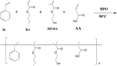
The acrylic copolymer was synthesised via a free radical polymerization route,24 as shown in Scheme 1. The reaction was conducted in a four-neck round-bottomed flask equipped with a mechanical stirrer, a reflux condenser, an addition funnel and a thermometer with nitrogen protection.25 The mixed solvents for the reaction include n-butyl alcohol and dimethylcarbinol. St, BA, HEMA and AA with a weight ratio of 4![[thin space (1/6-em)]](https://www.rsc.org/images/entities/char_2009.gif) :
:![[thin space (1/6-em)]](https://www.rsc.org/images/entities/char_2009.gif) 3:
3:![[thin space (1/6-em)]](https://www.rsc.org/images/entities/char_2009.gif) 1
1![[thin space (1/6-em)]](https://www.rsc.org/images/entities/char_2009.gif) :
:![[thin space (1/6-em)]](https://www.rsc.org/images/entities/char_2009.gif) 2 were used as the co-monomers. First, 50 wt% of the mixed solvent was added to the flask at room temperature, before being heated to 90 °C with continuous stirring under nitrogen protection. Next, 2/3 of the monomers, 40 wt% of the mixed solvent as well as 90 wt% of the catalyst (BPO) were fully mixed and instilled into the flask. After 2 h of reaction, the remaining solvents, BPO and monomers were added dropwise into the flask over a period of about 30 min. The polymerization was continued to improve the conversion of residual monomers. Finally, the reaction mixture was cooled down to room temperature and the acrylic copolymer was prepared.
2 were used as the co-monomers. First, 50 wt% of the mixed solvent was added to the flask at room temperature, before being heated to 90 °C with continuous stirring under nitrogen protection. Next, 2/3 of the monomers, 40 wt% of the mixed solvent as well as 90 wt% of the catalyst (BPO) were fully mixed and instilled into the flask. After 2 h of reaction, the remaining solvents, BPO and monomers were added dropwise into the flask over a period of about 30 min. The polymerization was continued to improve the conversion of residual monomers. Finally, the reaction mixture was cooled down to room temperature and the acrylic copolymer was prepared.
The silica sol precursor was synthesized in a conical flask with a magnetic stick stirring continuously. The first step was to take alcohol and 3-glycidoxypropyltrimethoxysilane into a conical flask with sufficient stirring for 30 min. Then, a certain amount of alcohol and deionized water were measured and instilled into the conical flask at 30–40 °C. Next, acid was used to adjust the pH to about 4–5. Finally, the reaction system was kept at 40 °C for 6 h.
For the preparation of a siloxane functionalised waterborne acrylic copolymer composite coating, the waterborne acrylic copolymer was first neutralised by TEA and ammonium hydroxide. Then, the acrylic copolymer was diluted with a moderate amount deionized water to pH = 10. Afterwards, a certain amount of silica sol precursor was added to the APC with moderate curing agent, the mass ratio of APC to silica sol precursor was 10![[thin space (1/6-em)]](https://www.rsc.org/images/entities/char_2009.gif) :
:![[thin space (1/6-em)]](https://www.rsc.org/images/entities/char_2009.gif) 1. At last, the aqueous dispersion of the mixing coating was prepared and the translucent appearance of the solution ensures the nanoscale dispersion of in situ generated silica particles.
1. At last, the aqueous dispersion of the mixing coating was prepared and the translucent appearance of the solution ensures the nanoscale dispersion of in situ generated silica particles.
2.3 Preparation of samples
Zinc-coated NdFeB sheets (60 mm × 30 mm × 5 mm) were used as substrates for APC-Si coating. They were also used as the substrates for EIS test, potentiodynamic polarisation test, the hardness test and NSS test. The metal substrates were degreased using alcohol solvent and dried in air before the experiments. The coatings were painted by roll coating method at room temperature (20 °C) and cured at 130 °C for 30 min. After the curing process, the samples were kept at room temperature for 1 day before being measured. The thickness of the obtained coatings was 2–3 μm, as measured by a coating thickness gauge (UTD20A, Ultra-Tech Corp., America).2.4 Measurements
The chemical structure of the waterborne acrylic copolymer was characterised by infrared spectra with a Fourier-transform infrared spectrum analyzer (FT-IR, Thermo Nicolet AVATAR, USA). The copolymer was dried to remove the solvent and the residue was pelleted with KBr for analysis. Thermogravimetric analyses (TGA) of the coating powders were conducted on an instrument (NETZSCH STA 449F3, Germany) to examine their decomposition behaviour. The TGA spectra were acquired in the temperature range from 30 °C to 550 °C at a heating rate of 5 °C min−1. The roughness of the coating surfaces was tested in an atomic force microscope (Veeco DI, USA the material of the cantilever is Si, the spring constant is 40 N m−1, and the frequency is 300 kHz). The height and phase images were obtained in a tapping-mode. All of the results were calculated by build-in software.The TEM test was operated on JEM-2100F and the coating was diluted ten-fold and painted on Cu mesh with a C-flat support film. SEM was used to observe the surface microtopography of the coating with a JSM-7500F (accelerating voltage is 5 kv; and detector is scintillator). SEM samples were prepared by dip-coating on the zinc-coated NdFeB sheet and then cured at 130 °C for 30 min. The NSS test was carried out in a salt-fog cabinet (Beijing Yashilin Experimental Equipments Ltd, China) with a spraying NaCl solution (5 wt%) at 35 °C. The electrochemical test was conducted in an electrochemical workstation (CHI 660E, Shanghai Chenhua instruments Ltd, China) with a three-electrode system at room temperature. The specimen with transversal area of 1 cm2 was set as working electrode. A saturated calomel electrode (SCE) was the reference and a platinum plate electrode was set as the counter. All measurements were performed in potentiostatic mode at the open circuit potential (OCP), and the EIS measurements were carried out at OCP. The amplitude of the sinusoidal voltage excitation was 5 mV and the frequency range was set from 105 to 10−2 Hz. The potentiodynamic polarization measurements were performed with a constant voltage scan rate of 1 mV s−1. The corrosive medium for the electrochemical tests were 3.5 wt% NaCl solutions.
Crosslinking degree of waterborne acrylic copolymer–siloxane composite was determined by Soxhlet extraction.26 That is, a certain mass of the copolymer film was extracted in boiling mixed N,N-dimethylformamide (DMF) and tetrahydrofuran (THF) for 24 h, and the crosslinking degree was calculated by eqn (1),
 | (1) |
Other application properties of APC and APC-Si coatings were measured as follows: the hardness was tested with a pencil, with a different hardness on zinc-coated NdFeB sheet (GB/T 6739-2006); and water absorption of the films was evaluated following a standard method (HG/T 3856-2006).
3. Results and discussions
3.1 Preparation and characterisation of the APC-Si
The hydrolysing mechanism of the siloxane is shown in Fig. 1. It was first hydrolysed into Si–OH and a part of Si–OH will generate a two-dimensional network of Si–O–Si instead of silica particles from polycondensation in acidulous condition. In the second stage, the pH value of the APC solution changed the stability of silica sol precursor and generated triaxial silica particles by condensation during mixing process. In addition, the epoxy groups of the silica sol precursor were able to react with the hydroxyl of the acrylic polymer with the TEA as the catalyst during the heating process (Fig. 1a). Meanwhile, the Si–OH could also react with the hydroxyl of the acrylic polymer (Fig. 1b). Therefore, the surfaces of the silica particles could be covered with a certain amount of chain segments from the acrylic polymer. In this system, the silica sol also acted as a bridge which connected the APC with the inorganic segments. In order to verify the reaction model, the FTIR, TEM, AFM, SEM and TGA were tested.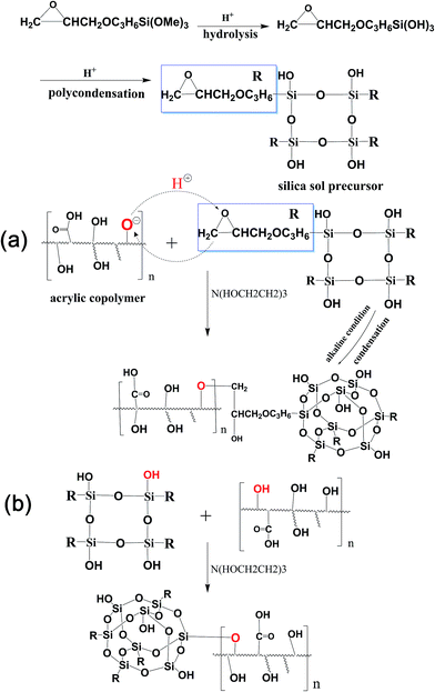 | ||
| Fig. 1 Schematic of chemical reaction between the hydroxyl of waterborne acrylic copolymer and the epoxy groups (a); the Si–OH (b) of silica sol. | ||
Measurements using FT-IR was conducted to see whether the silica sol was successfully introduced into the APC. As can be seen from Fig. 2, the spectra of APC-Si (a) showed all of the characteristic absorption bands of APC (b), but new characteristic peaks appeared at 1000–1100 cm−1 and 908–913 cm−1. All of these new peaks were also found in the spectra of silica sol (c). Fig. 2A showed more details from 880–950 cm−1, which represented the oxirane ring vibration.27 However, the intensity of oxirane ring vibration in APC-Si is weaker than that in silica sol. It may be attributed to the progress of epoxide ring-opening reaction in the silica sol, which caused a similarly reaction in Fig. 1a. It can be seen in Fig. 2B that characteristic peaks at 1000–1100 cm−1 belonged to “Si–O–Si” and they both appeared in APC-Si and silica sol. The existence of these peaks suggested two things: (1) the silica sol was successfully introduced into the APC; and (2) it already formed the planar reticulate structure of “Si–O–Si” or triaxial globular structure.
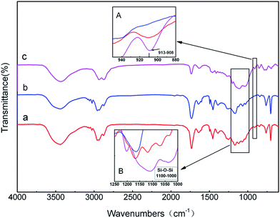 | ||
| Fig. 2 FT-IR spectra of (a) APC-Si; (b) APC and (c) silica sol and partial detail at 908–913 cm−1 (A); 1000–1100 cm−1 (B). | ||
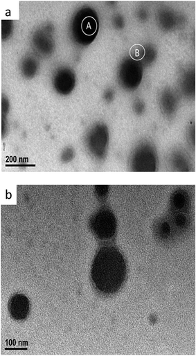
Fig. 3 displays the TEM images of the APC-Si sample. It is apparent that the diameter of silica particle was approximately 100 nm with a wide size distribution. Due to the silica particles being connected by acrylic copolymers, the TEM micrograph appears slightly blurry. As can be seen, there was a halo around the dark regions which indicated that not only a physical sheathe may exist, but also a chemical reaction (see Fig. 1.). It has been observed that the average diameter of the silica particles is low due to the polarity of the polymer backbone covering the in situ generated silica particles.21
The content of the elements on marked A and B areas are listed in Table 1. The ratio of O and Si was approximately 4![[thin space (1/6-em)]](https://www.rsc.org/images/entities/char_2009.gif) :
:![[thin space (1/6-em)]](https://www.rsc.org/images/entities/char_2009.gif) 1 in the A areas, which was similar to the B areas. However, the Si and O elements content in A areas were more than in B areas. Therefore, it can be concluded that the black particles were silica particles which were covered with organic chain segments (see Fig. 3b). The results also confirm the possibility of the reaction mechanism in Fig. 1.
1 in the A areas, which was similar to the B areas. However, the Si and O elements content in A areas were more than in B areas. Therefore, it can be concluded that the black particles were silica particles which were covered with organic chain segments (see Fig. 3b). The results also confirm the possibility of the reaction mechanism in Fig. 1.
| Elements | (A areas) | (B areas) | ||
|---|---|---|---|---|
| wt% | at% | wt% | at% | |
| C | 78.64 | 85.35 | 95.27 | 96.86 |
| O | 13.50 | 11.00 | 3.32 | 2.53 |
| Si | 7.86 | 3.65 | 1.41 | 0.61 |
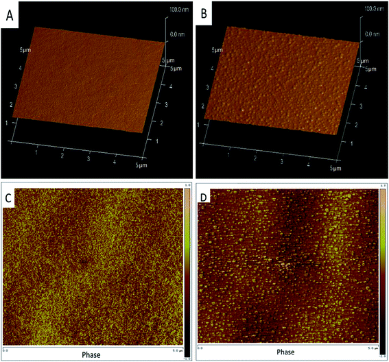
AFM images can be used to observe the roughness and phase differences of the coating surface. Fig. 4A shows the height images of APC coated in zinc-coated NdFeB sheet and C shows the phase images. As can be seen from Fig. 4A and C, the APC was smooth and compact and the root-mean-square roughness (Rq) was about 0.5 nm. Compared with APC, the APC-Si appeared equally distributed bright embossment (Fig. 4B), which was consistent with the phase images in Fig. 4D. The bright regions represented the rigid phase and the dark regions represented the soft phase.28 In APC-Si, the stiffer regions were assigned to the nanometre organic silica particles, where the soft regions belonged to the hydrocarbon segments. As can be seen from Fig. 4B and D, the silica sol particles can be distributed uniformly in the APC. Although distinct particles phase existed, the Rq was 0.8 nm. This was ascribed to the fact that the acrylic copolymer or side organic segments of silica sol particles covered their surfaces and prevented the silica particles from combining. Therefore, the silica particles can distribute uniformly in the APC. In addition, these stiff phases can be used as organic fillers which would improve the hardness and scratch resistant of the coating.
Fig. 5A shows the surface micrographs of the zinc-coating on NdFeB, which contained many defects on the rough surface. These defects may become the sources and channels of corrosions. However, the APC coated on zinc-coated NdFeB (Fig. 5B) was smooth and compact. A lot of three-dimensional particles with a grain size of about 100 nm can be seen in Fig. 5C. These particles can be attributed to the silica nanoparticles that in situ generated by hydrolysis and polycondensation of silica sol precursor. The SEM images of the cross-linked hybrid composites confirmed the presence of silica nanoparticles. The compact film is beneficial to protect the substrates from permeating of corrosive ions.
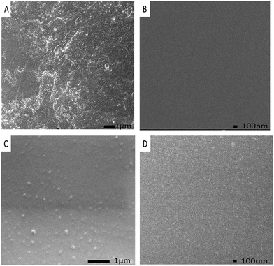 | ||
| Fig. 5 SEM images of (A) the zinc-coating; (B) the APC; (C) the APC-Si; (D) the silica sol on zinc-coated NdFeB. | ||
This observation corroborates well with the results of the bright regions in Fig. 4D. It can also be seen from Fig. 5C that the silica particles dispersed evenly both in APC and APC-Si. Therefore, the silica particles have a good dispersion in the APC. This could be attributed to the polymer backbone that controls the size of the in situ generated silica particles and the side chains of silica particles which prevent their combining. As a result, the nanoparticles will also contribute to blocking the defects or microvoids of the APC-Si and the zinc-coated NdFeB.
The cross-section surface of the APC-Si coated on the specimens with epoxy resin sealed is exhibited in Fig. 6. It was designed to confirm the thickness and combining state of the APC-Si and zinc-coated NdFeB. As can be seen, the APC-Si coating was well adhesive to the substrate without obvious cracks or inclusions at the interfaces. The thickness of the APC-Si coating was approximately 2–3 μm.
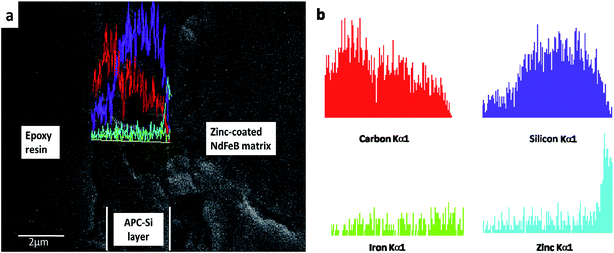 | ||
| Fig. 6 SEM images (a) and EDS line scanning (b) of the cross-section of APC-Si on zinc-coated NdFeB and sealed sample with epoxy resin. | ||
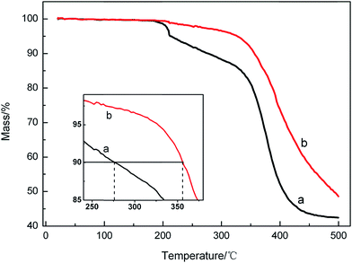
The thermal stability of different samples was investigated with TGA studies (Fig. 7). The TGA thermograms of the cured coatings showed that the thermal degradation of the APC (Fig. 7a), APC-Si (Fig. 7b) started at 210 °C for 5%, 1% weight loss, respectively, which may be due to the solvent evaporation.29 The decline from 210 °C to 320 °C may be attributed to the decomposition of micromolecule. All of the samples began to degrade quickly at 320 °C (about 40–50 wt% loss at this stage), which can be correlated to the de-crosslinking and decomposition of the copolymer. The temperatures for 10% weight loss of APC, APC-Si were 275 °C, 355 °C, which improved by about 80 °C. The results reflected that adding silica sol into the APC improved the decomposition temperatures, which attributed to the crosslinking groups of the silica sol such as Si–OH and the epoxy groups.30 Due to the silica sol improving the crosslinking density of the APC, the APC-Si showed higher decomposition temperatures and slower decomposition rates compared to APC. It could be concluded that the silica sol contributed better heat resistance to the copolymer.
3.2 Corrosion resistance properties of the APC-Si
The anodic portion of polarization curves can provide more information about the electrochemical corrosion behaviours. It can be seen from Fig. 8 that the bare zinc-coated NdFeB sheet exhibited active dissolution in the anodic region and showed much higher anodic current densities. Both the APC and APC-Si exhibited a passive-like anodic behaviour. Finally, the anodic current densities remain at a low value compared with the bare one. In addition, the natural corrosion potential (Ecorr) of APC-Si (−0.942 V/SCE) was higher than APC (−0.973 V/SCE), which indicated that APC-Si had higher anticorrosion tendency. The corrosion current densities (icorr) of the APC-Si (10−7.618 A cm−2) and the APC (10−6.28 A cm−2) were approximately two or three times smaller than that of the bare zinc-coated NdFeB (10−4.657 A cm−2). The results indicated that both the APC and APC-Si can effectively improve the corrosion resistance of the bare zinc-coated NdFeB. The lower icorr of the APC-Si indicated that it has better corrosion resistance than APC.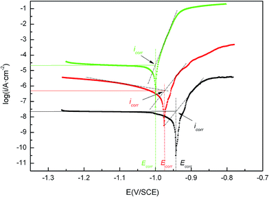 | ||
Fig. 8 Potentiodynamic polarisation curves of different specimens: ( ) the bare zinc-coated NdFeB; ( ) the bare zinc-coated NdFeB; ( ) the APC and ( ) the APC and ( ) the APC-Si in neutral 3.5 wt% NaCl solution. ) the APC-Si in neutral 3.5 wt% NaCl solution. | ||
As can be seen in Fig. 9, the EIS plots show two stages: it can be seen that APC-Si exhibited the highest impedance value, followed by APC and the bare one performed worst.31 Therefore, it can be concluded that the APC-Si layer exhibited much better corrosion resistance than that of the APC, and it should be attributed to the Si–O–Si and the side chains of the silica sol which improved the compactness and completeness of the APC. Therefore, the APC-Si layer could block the defects and electron transport channels.
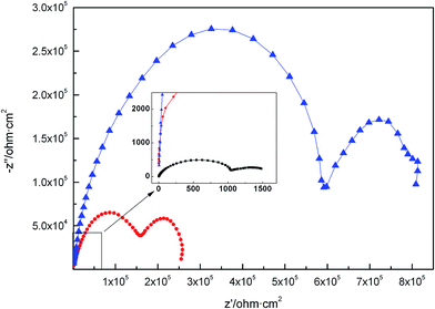 | ||
Fig. 9 EIS plots of bare zinc-coated NdFeB ( ); APC ( ); APC ( ) and APC-Si ( ) and APC-Si ( ) coating in neutral 3.5 wt% NaCl solutions. ) coating in neutral 3.5 wt% NaCl solutions. | ||
The equivalent circuit R(C(R(QR)))(CR) shown in Fig. 10 was used to fit the EIS plots of APC and APC-Si in a 3.5 wt% NaCl solution.32 Rsol represents the solution resistance; constant phase angle element (CPE, designated as Q) was used instead of the pure capacitance; Cc and Rc are defined as the capacitance and resistance of the APC-Si and APC coating corresponding to the high-frequency region. The CPE and Rt represent the double-layer capacitance of the polymer complex at the zinc interface and charge transfer resistance, respectively. CPc and RPc were capacitance and resistance of the corrosion products from the dissolution of Zn coating at a low-frequency.33 The CPE (Y − Q(ω)) impedance is given by eqn (2):
| Y − Q(ω) = Y0(jω)n | (2) |
The capacitance and resistance in high-frequency were attributed to the existence of the protective coating. Due to the compactness of the coating, the solute ions in the solution had difficulty reaching the zinc layer. Meanwhile, the redundant positive charge in NdFeB transferred to the interface of the zinc layer and the coating. Finally, a double-layer was formed, which connected in parallel with the coating. The capacitance and resistance in the low frequency part could be associated with the deposited corrosion products of the combination of zinc coating, inhibitor and polymer complex. As can be seen from the EIS plots, the APC and APC-Si all improved the protective capability of the zinc layer. The resistance of APC-Si (Rc) reached up to 3.66 × 10⁵ Ω cm2 (Table 2) which was higher than 1.30 × 10⁵ Ω cm2 of the APC. The results suggested better anticorrosive properties of APC-Si than that of APC. Due to the interaction of the coating, it could be formed the “Zn–O–Si” structure which would inhibit the electrochemical corrosion reaction.8 It could be concluded that the resin coating improved the compactness of the zinc layer and decreased its defects. The fitting data obtained from software were relatively consistent with the experimental data and the errors were smaller than 3%.
| Sample | Rsol (Ω cm2) | Cc (F cm−2) | Rc (Ω cm2) | CPE | Rt (Ω cm2) | CPc (F cm−2) | RPc (Ω cm2) | |
|---|---|---|---|---|---|---|---|---|
| Y0 − Q (μS cm−2 Sn) | n | |||||||
| APC | 10.10 | 5.11 × 10⁻⁸ | 1.30 × 10⁵ | 0.89 | 0.80 | 1.63 × 10⁵ | 2.46 × 10⁻⁶ | 9.63 × 10⁴ |
| APC-Si | 12.57 | 3.78 × 10⁻⁸ | 3.66 × 10⁵ | 0.11 | 0.82 | 5.60 × 10⁵ | 1.64 × 10⁻⁶ | 2.73 × 10⁵ |
In order to further study the protective properties of APC and APC-Si for the zinc-coated NdFeB, long-term NSS testing has been carried out. Fig. 11 showed the morphology of the zinc-coated NdFeB substrate coated with APC (Fig. 11a), APC-Si (Fig. 11b) exposed to neutral salt spray environment for 480 h. There were some corrosion pits in Fig. 11a, while few corrosion pits appeared in Fig. 11b. The corrosion expansion test, which could verify the corrosion growth behaviour, was carried out in the same neutral salt spray environment for 480 h. As can be seen, the scarification in Fig. 11d was clear; however, the edge of the scarification in Fig. 11c was blurry and broken. The APC-Si performed best in corrosion resistance and showed a slower corrosion growth rate combining these two aspects. It can be attributed to the compact crosslinking network of the APC-Si and its good adhesion to the substrate. Table 3 shows the crosslinking degree of two waterborne acrylic copolymer films formed at various temperatures. It can be seen that crosslinking degree of APC and APC-Si films increased as the film forming temperature increasing. In addition, crosslinking degree of APC-Si was higher than APC at the same curing temperature. It can be concluded that the siloxane plays an important effect on crosslinking reaction. The result indicated that the introduced silica sol changed the crosslinking structure of the APC and the APC-Si formed a compact film which could hinder the penetration of corrosive medium.
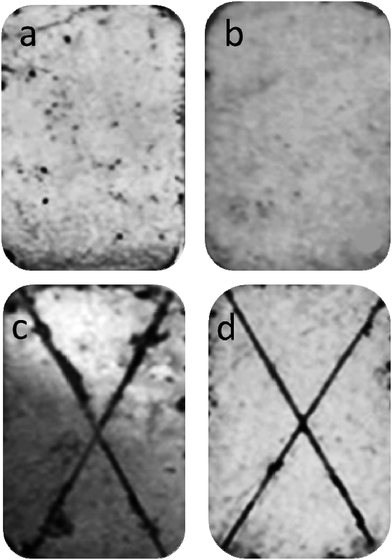 | ||
| Fig. 11 Neutral salt spray of (a) APC; (b) APC-Si and corrosion expansion test of (c) APC; (d) APC-Si after 480 h. | ||
| Film forming temperature (°C) | 100 | 130 | 150 |
| APC | 51.0 | 62.5 | 66.7 |
| APC-Si | 59.8 | 74.3 | 75.0 |
The performances of APC-Si can meet application demand. The pencil hardness of APC-Si and APC was 4H and 2H, respectively. The water absorption of the APC-Si was 5.8 wt%, which was lower than the APC (9.5 wt%). The results of the application test indicated that adding the silica sol into the APC could improve compactness and mechanical properties of the coatings, due to the improved crosslinking property.34
4. Conclusion
The environmentally friendly acrylic copolymer waterborne coating modified with in situ silica sol (APC-Si) was successfully prepared. The silica sol could improve the compactness of the APC in two ways: (1) the epoxide ring-opening reaction; and (2) the reaction between Si–OH and the active groups of acrylic copolymer. The aqueous dispersion of APC-Si was clear, translucent and stable. As can be seen from the results the APC-Si had improved the properties of the film such as water resistance, compactness, and thermostability. The APC-Si, which possesses a compact cross-linked structure presented a superior corrosion resistance and scratch resistance for zinc-coated NdFeB sheets compared with APC. The application properties showed that the APC-Si films exhibited good adhesion on the metal sheets, good gloss and hardness. These results demonstrated that the film-forming properties and corrosion resistance of the waterborne acrylic copolymer coating was actually enhanced by introducing silica sol in situ.References
- M. Sagawa, S. Fujimura, N. Togawa, H. Yamamoto and Y. Matsuura, J. Appl. Phys., 1984, 55, 2083 CrossRef CAS PubMed.
- A. A. El-Moneim and A. Gebert, J. Appl. Electrochem., 2003, 33, 795–805 CrossRef CAS.
- I. Gurappa, J. Alloys Compd., 2003, 360, 236–242 CrossRef CAS.
- H. Bala, G. Pawlowska, S. Szymura and Y. M. Rabinovich, Br. Corros. J., 1998, 33, 37–41 CrossRef CAS PubMed.
- S. M. Tamborim Takeuchi, D. S. Azambuja, A. M. Saliba-Silva and I. Costa, Surf. Coat. Technol., 2006, 200, 6826–6831 CrossRef CAS PubMed.
- C. W. Cheng, F. T. Cheng and H. C. Man, J. Appl. Phys., 1998, 83, 6417 CrossRef CAS PubMed.
- C. W. Cheng, H. C. Man and F. T. Cheng, IEEE Trans. Magn., 1997, 33, 3910–3912 CrossRef CAS.
- F. Liu, Q. Li, X. K. Yang, Y. Dai, F. Luo, S. Y. Wang and H. X. Zhang, Mater. Corros., 2011, 62, 1141–1148 CrossRef CAS PubMed.
- Y. Hu, M. Aindow, I. P. Jones and I. R. Harris, J. Alloys Compd., 2003, 351, 299–303 CrossRef CAS.
- K. Ramesh, Z. Osman, A. K. Arof, B. Vengadaeswaran and W. J. Basirun, Pigm. Resin Technol., 2008, 37, 37–41 CrossRef CAS.
- R. Parmar, K. Patel and J. Parmar, Polym. Int., 2005, 54, 488–494 CrossRef CAS PubMed.
- M. Elrebii and S. Boufi, J. Ind. Eng. Chem., 2014, 20, 3631–3638 CrossRef CAS PubMed.
- M. Elrebii, A. Ben Mabrouk and S. Boufi, Prog. Org. Coat., 2014, 77, 757–764 CrossRef CAS PubMed.
- C. Zhang, X. Zhang, J. Dai and C. Bai, Prog. Org. Coat., 2008, 63, 238–244 CrossRef CAS PubMed.
- K. Zhang, H. Q. Fu, H. Huang and H. Q. Chen, J. Dispersion Sci. Technol., 2007, 28, 1209–1217 CrossRef CAS PubMed.
- G. D. Chen, S. X. Zhou, H. M. Liao and L. M. Wu, J. Compos. Mater., 2005, 39, 215–231 CrossRef CAS PubMed.
- J. Ou, M. Zhang, H. Liu, L. Zhang and H. Pang, J. Appl. Polym. Sci., 2015, 132, 41707–41714 CrossRef PubMed.
- A. Mirabedini, S. M. Mirabedini, A. A. Babalou and S. Pazokifard, Prog. Org. Coat., 2011, 72, 453–460 CrossRef CAS PubMed.
- S. Patel, A. Bandyopadhyay, V. Vijayabaskar and A. K. Bhowmick, Polymer, 2005, 46, 8079–8090 CrossRef CAS PubMed.
- M. Watanabe and T. Tamai, J. Polym. Sci., Part A: Polym. Chem., 2006, 44, 4736–4742 CrossRef CAS PubMed.
- S. Patel, A. Bandyopadhyay, V. Vijayabaskar and A. K. Bhowmick, J. Mater. Sci., 2006, 41, 927–936 CrossRef CAS.
- P. Hajji, L. David, J. F. Gerard, J. P. Pascault and G. Vigier, J. Polym. Sci., Part B: Polym. Phys., 1999, 37, 3172–3187 CrossRef CAS.
- G. Kickelbick, Prog. Polym. Sci., 2003, 28, 83–114 CrossRef CAS.
- D. Han, L. Zhu, Y. Chen, W. Li, X. Wang and L. Ning, RSC Adv., 2015, 5, 22847–22855 RSC.
- X. Yang, L. Zhu, Y. Zhang, Y. Chen, B. Bao, J. Xu and W. Zhou, Appl. Surf. Sci., 2014, 295, 44–49 CrossRef CAS PubMed.
- G. Hao, L. Zhu, W. Yang and Y. Chen, Prog. Org. Coat., 2015, 85, 8–14 CrossRef CAS PubMed.
- S. Zafar, F. Zafar, U. Riaz and S. Ahmad, J. Appl. Polym. Sci., 2009, 113, 827–838 CrossRef CAS PubMed.
- D. Han, L. Zhu, Y. Chen, W. Li and L. Feng, J. Fluorine Chem., 2013, 156, 38–44 CrossRef CAS PubMed.
- D. Han, L. Zhu, Y. Chen, W. Li, X. Wang and L. Ning, J. Appl. Polym. Sci., 2015, 132, 41926–41933 Search PubMed.
- L. Li, X. Chen and B. He, J. Vinyl Addit. Technol., 2007, 13, 103–109 CrossRef CAS PubMed.
- M. Liu, X. Mao, H. Zhu, A. Lin and D. Wang, Corros. Sci., 2013, 75, 106–113 CrossRef CAS PubMed.
- S. Mao, H. Yang, Z. Song, J. Li, H. Ying and K. Sun, Corros. Sci., 2011, 53, 1887–1894 CrossRef CAS PubMed.
- O. Hammami, L. Dhouibi, P. Berçot, E. M. Rezrazi and E. Triki, Can. J. Chem. Eng., 2013, 91, 19–26 CrossRef CAS PubMed.
- Z. Ge and Y. Luo, Prog. Org. Coat., 2013, 76, 1522–1526 CrossRef CAS PubMed.
| This journal is © The Royal Society of Chemistry 2015 |

